Week 14

Interface and Application Programming

Group Assignment

LINK TO THE GROUP ASSIGNMENT PAGE
Take a look:

compare as many tool options as possible

Individual Assignment

Take a look:

write an application that interfaces a user with an input &/or output device that you made

Organization

Here is my organization to finish on time:

LINK TO THE ASSIGNMENT WEEK

Organization Of Week 14
Thursday 2nd Sketching the first impressions about the project
Friday 3th Completion of research on different languages and platforms for programming.
Monday 6th Last tests with outputs and visualisation of the processing
Tuesday 7th Documentation and project completion day

Group Assignment

COMPARING MANY TOOL OPTIONS

HTML CODE

The purpose of using this language is to light an LED on my Xiao ESP32-C3 board using HTML and Visual Studio Code, for this I need to write a program in C/C++ language using the ESP-IDF development environment, which is compatible with Visual Studio Code. Here I guide you step by step:

Prerequisites

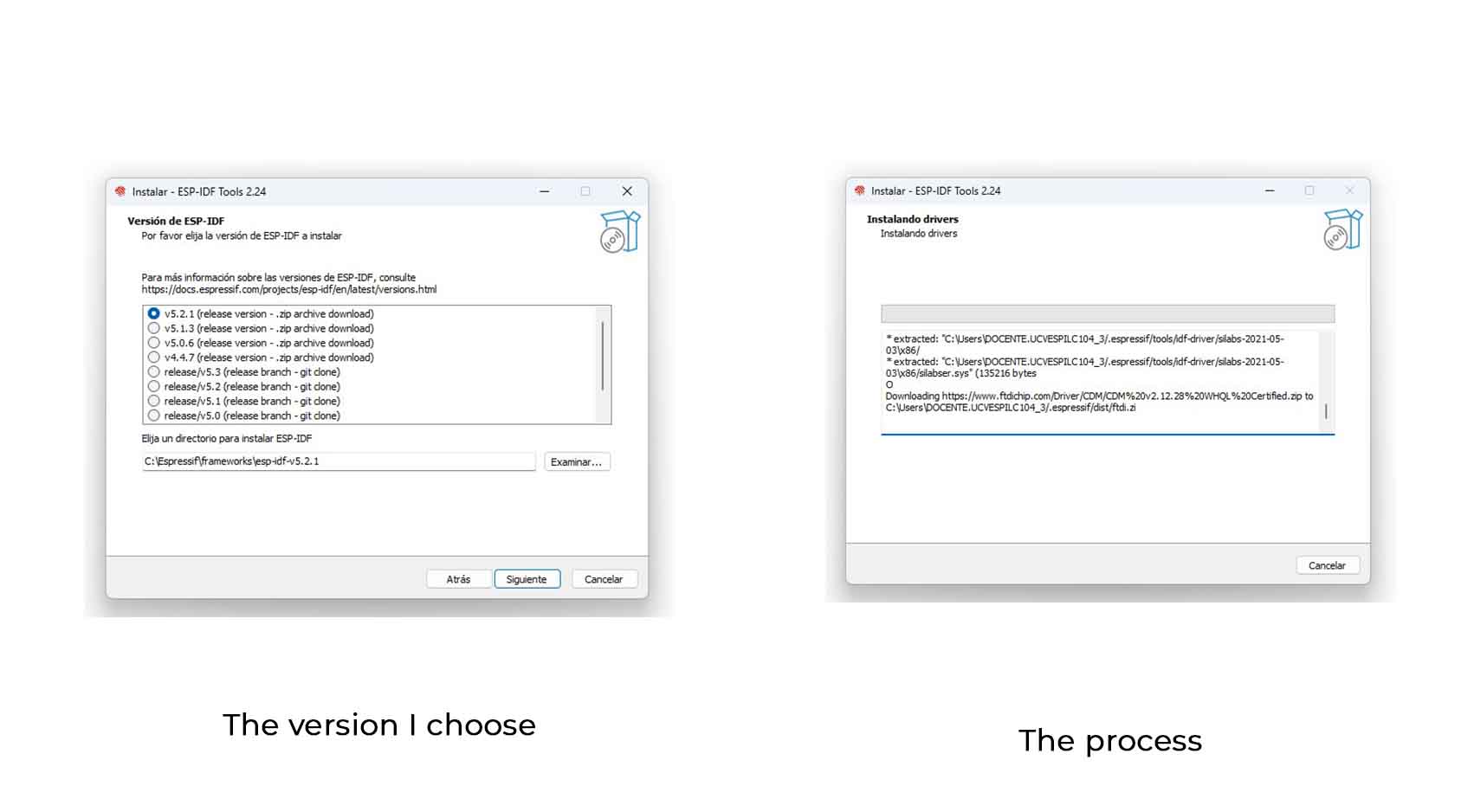
1. ESP-IDF Installation and Tools

Make sure you have installed ESP-IDF and the necessary development tools by following the official instructions.

Descripción de la imagen Descripción de la imagen

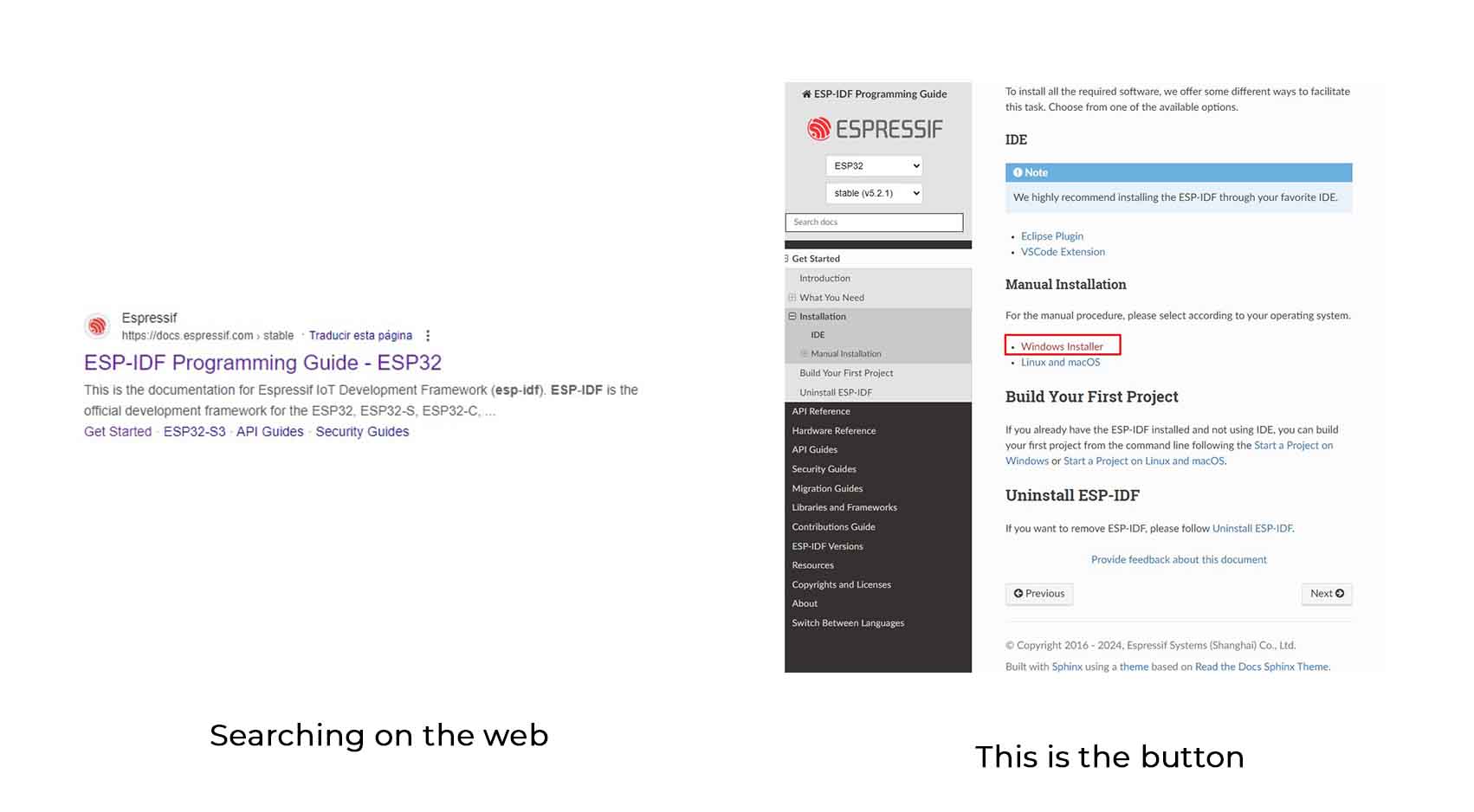
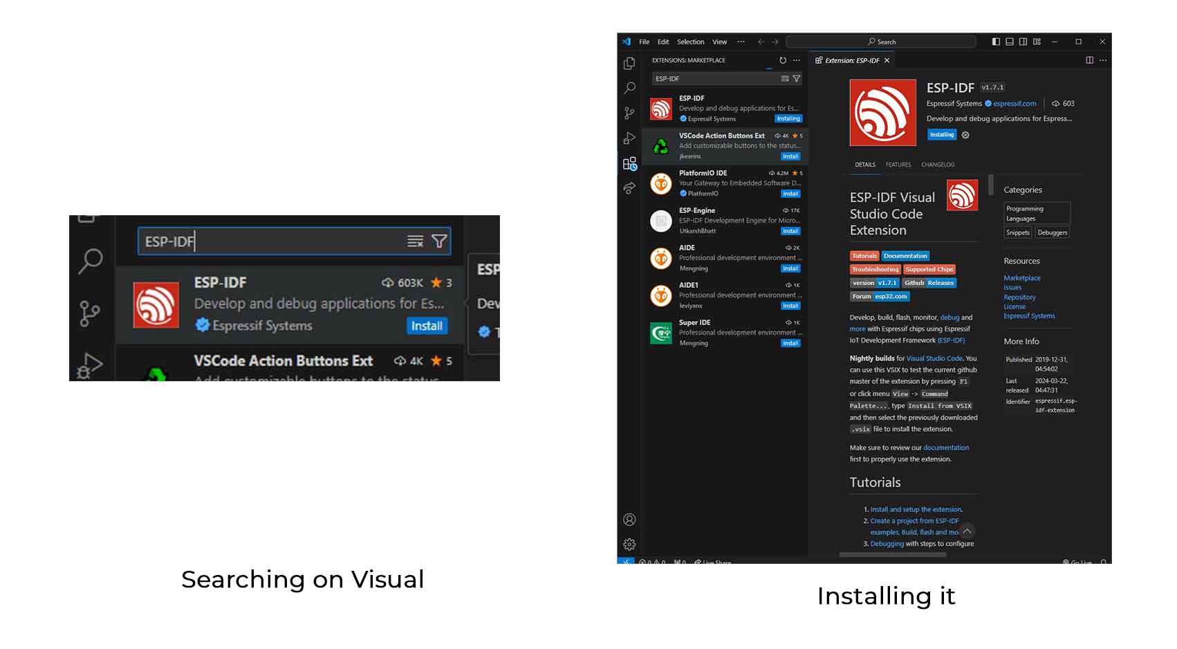
2. Visual Studio Code Configuration

Install the ESP-IDF extension in Visual Studio Code to configure your development environment.

Descripción de la imagen

Project Creation

1. Initialising the Project

Open a terminal in Visual Studio Code and start a new ESP-IDF project with the command:

idf.py create-project esp32c3-led

Next, navigate to the project directory

cd esp32c3-led

2. Code Configuration

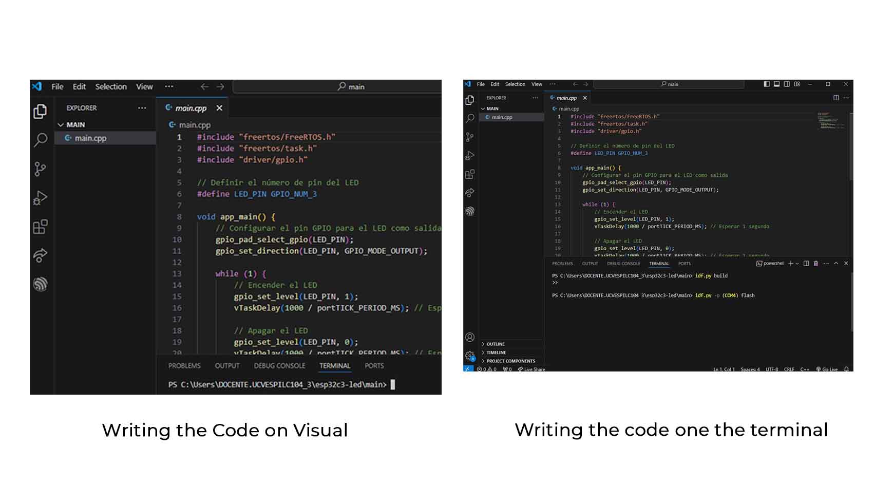
Open the main/main.cpp file in your project and write the following code:

#include "freertos/FreeRTOS.h"
      #include "freertos/task.h"
      #include "driver/gpio.h"
      
      // Definir el número de pin del LED
      #define LED_PIN GPIO_NUM_3
      
      void app_main() {
          // Configurar el pin GPIO para el LED como salida
          gpio_pad_select_gpio(LED_PIN);
          gpio_set_direction(LED_PIN, GPIO_MODE_OUTPUT);
      
          while (1) {
              // Encender el LED
              gpio_set_level(LED_PIN, 1);
              vTaskDelay(1000 / portTICK_PERIOD_MS); // Esperar 1 segundo
      
              // Apagar el LED
              gpio_set_level(LED_PIN, 0);
              vTaskDelay(1000 / portTICK_PERIOD_MS); // Esperar 1 segundo
          }
      }
      
Descripción de la imagen

Compiling and Loading the Program

1. Compilation

In the Visual Studio Code terminal, run the command to compile the project:

idf.py build 

I searched for the error with AI tools, but they told me that it might be an ESP-IDF installation error, so I uninstalled it and I still got the error.

Descripción de la imagen

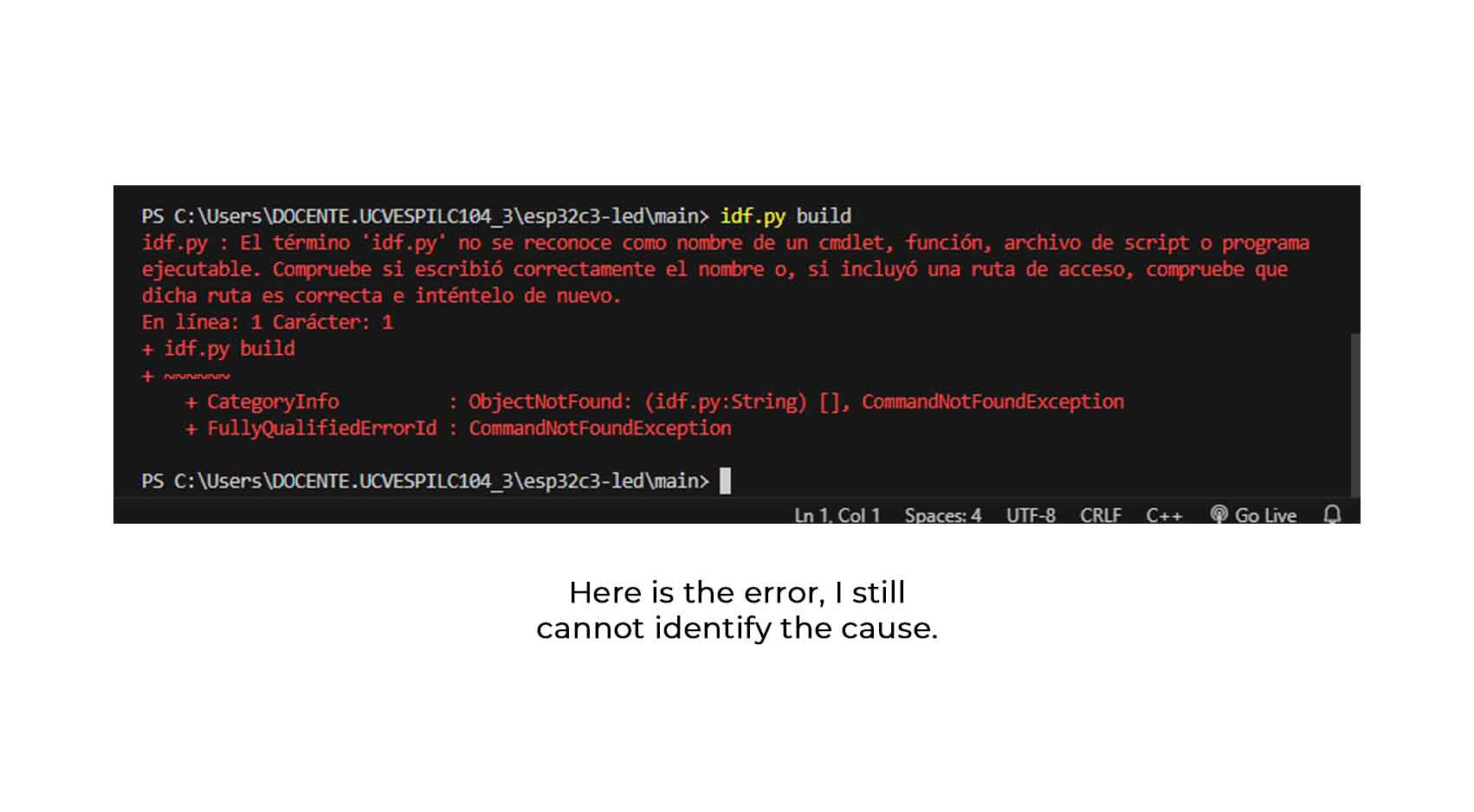
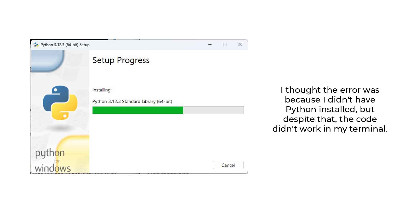
From here I leave you the next steps, I tried to verify that maybe the error was because I didn't have Python installed, I leave you my screenshots of the installation.

Descripción de la imagen

2. Loading the Programme

Connect your Xiao ESP32-C3 board to your computer via USB.

Upload the program to the board with the command:

idf.py -p (puerto_USB) flash

Replace (USB_port) with the serial port where your board is connected (for example, /dev/ttyUSB0 on Linux or COM1 on Windows).

Verification

Once the program has been successfully loaded, the LED connected to pin D3 on your board should start flashing, turning on and off every second.

I didn't get any results! but I will continue my search to identify the error from here, I won't give up!

Individual Assignment

AN APP THAT CAN DO SOMETHING

Defining my application and what it will do

What I want to do is to make an application that can determine the color of an Output, in this case the Neopixel, doing a review of environments to work my app I decided to use the MIT INVENTOR APP.

LINK TO MIT APP INVENTOR

In the app, click on CREATE APPS!, from here another environment will open where we will click on NEW PROJECT.

Descripción de la imagen Descripción de la imagen

From this environment, we rename the new project and give it OK.

The initial design

Here I changed the device to an Iphone interface, from here I started to discover this environment, where the left bar shows a list of resources to add on the device screen, the correct way is to drag it on the screen and will appear on the right bar, the list of order as a history of all additions of the app, with free settings of size, shape, thickness, font, etc..

Descripción de la imagen

Here I left an example of the creation of a slider that I will need to be able to make the color change of my Neopixel, the component is called SLIDER, its configurations are based on the position, color of the selector and thickness of the same one.

Descripción de la imagen

In the case of the button, it is found in the USER INTERFACE list, called Button, which has the characteristic of having rounded edges.

Descripción de la imagen

With the design ready, what we can do to verify that everything is ok! is to go to the CONNECT tab and click on AI COMPANION, where it will give us a qr code + code to place on our mobile device (previously you have had to download the app on your mobile phone) LINK HERE

Descripción de la imagen Descripción de la imagen

From your mobile device you can now verify that it is working properly and if you like the design.

Descripción de la imagen

Programming the buttons

To program the buttons, I started by selecting the Red Slider to give it an action, in this case, when the position changes I set the colour in Ball 1 and it is painted according to the other colour selectors. I repeat this for all cases (the green and blue slider).

Descripción de la imagen

On the next buttons I started to program the Bluetooth device list buttons, so that I send a text through the colour list of the selectors through a code for the microcontroller to read.

The configuration is also completed when the Bluetooth button is pressed before or after.

Descripción de la imagen

APPLICATION OF THE APP

Installing my app on Android

To be able to use the app, with the configurations made, it is necessary to Build the application to be installed, so through the BUILD tab click on Android App (.apk).

Descripción de la imagen

When the app is finished, it will appear on your device like this:

Descripción de la imagen

Testing the app

Now it's time to test it, so first I click on ‘Bluetooth devices list’, select the device called ‘Neopixel Control’, and after waiting for the connection I should be able to change the colours using the selectors and finally hit Set the Color!

Descripción de la imagen

But here an error occurred, the microcontroller was shown as not switched on, even though I had loaded the code correctly, and the BLE did identify the device, so I could not identify what had happened.

Descripción de la imagen

I'm still looking for what the mistake was, while I kept using other ways to do this assignment!

MOVING OBJECTS AND TURNING THINGS ON

Moving a servo with my Mouse

In this case I decided to use the Xiao RP2040 for programming.

First download the Processing program from this website:

Descripción de la imagen

The servo is programmed with code in the Arduino to identify that it is working and also to identify the correct pin.

        #include 

            #define SERVO_PIN 3
            
            Servo myServo;
            
            void setup() {
              Serial.begin(9600);
              myServo.attach(SERVO_PIN);
            }
            
            void loop() {
              if (Serial.available() > 0) {
                int angle = Serial.parseInt(); // Lee el ángulo del servo desde el puerto serial
                
                // Limita el ángulo dentro del rango válido
                angle = constrain(angle, 0, 180);
                
                // Mueve el servo al ángulo recibido
                myServo.write(angle);
              }
            }
      

After identifying that the servo is working, I include the code in the Processing to make it work through my mouse, here is the code

        import processing.serial.*;

Serial myPort;  // Objeto Serial para la comunicación con la placa XIAO RP2040

void setup() {
  size(400, 400);  // Tamaño de la ventana de la interfaz
  myPort = new Serial(this, "COM6", 9600);  // Inicializa la comunicación serial con el puerto donde está conectada la placa XIAO RP2040
}

void draw() {
  // No necesitamos dibujar un fondo en cada fotograma para evitar que se borre la pantalla
  // Si dibujas el fondo aquí, todo lo que se dibuje en el siguiente frame lo ocultará
}

// Función que se ejecuta cuando se mueve el mouse
void mouseMoved() {
  // Envía el ángulo del servo motor a la placa XIAO RP2040
  int angle = 90;
  if (mouseX < width/3) {
    angle = 0;
  } else if (mouseX < 2*width/3) {
    angle = 90;
  } else {
    angle = 180;
  }
  myPort.write(angle + "\n"); // Añade un salto de línea al final del mensaje para que Arduino pueda leerlo correctamente
}
      

Here's a video of how it works! I got a bit excited at the end because it did work :’)

Controlling the brightness of a Neopixel

To make the Neopixel work, I uploaded the code to ARDUINO that I need at the moment:

        #include 

            #define NEOPIXEL_PIN 3
            #define NUM_PIXELS 16  // Ajusta esto al número de LEDs de tu Neopixel
            
            Adafruit_NeoPixel strip(NUM_PIXELS, NEOPIXEL_PIN, NEO_GRB + NEO_KHZ800);
            
            void setup() {
              strip.begin();
              strip.show();  // Inicializa todos los LEDs a apagado
              Serial.begin(9600);
            }
            
            void loop() {
              if (Serial.available() > 0) {
                int brightness = Serial.parseInt(); // Lee el brillo desde el puerto serial
                brightness = constrain(brightness, 0, 255); // Limita el brillo dentro del rango válido
                for (int i = 0; i < NUM_PIXELS; i++) {
                  strip.setPixelColor(i, strip.Color(brightness, 0, 0)); // Rojo con brillo variable
                }
                strip.show(); // Actualiza los LEDs
                delay(50); // Pequeña pausa para evitar problemas de comunicación
              }
            }
      

To make it work with Processing, I place this code:

        import processing.serial.*;

   Serial myPort;  // Objeto Serial para la comunicación con la placa XIAO RP2040
   int brightness = 0; // Brillo inicial del Neopixel

   void setup() {
   size(400, 200);  // Tamaño de la ventana de la interfaz
   myPort = new Serial(this, "COM6", 9600);  // 
    }

   void draw() {
   background(255);  // Fondo blanco
  
  // Dibuja un rectángulo que representa el brillo del Neopixel
  fill(255, 0, 0);  // Color rojo para el rectángulo
  rect(50, 50, map(brightness, 0, 255, 0, 300), 100);
   }

  // Función que se ejecuta cuando se presiona el mouse
   void mousePressed() {
  // Calcula el brillo del Neopixel en función de la posición del mouse
  brightness = int(map(mouseX, 0, width, 0, 255));
  myPort.write(brightness + "\n"); // Envía el brillo al Arduino
   }
      

Here is a video of how it works! everything is great

SOME FILES TO DOWNLOAD

APK APP

ARDUINO CODE APP

SERVO IDENTIFY ARDUINO IDE

SERVO MOUSE PROCESSING

NEOPIXEL IDENTIFY ARDUINO IDE

NEOPIXEL MOUSE PROCESSING