Development of the group part such as inventory recognition, machinery and training, in addition to the development of parts and sockets.
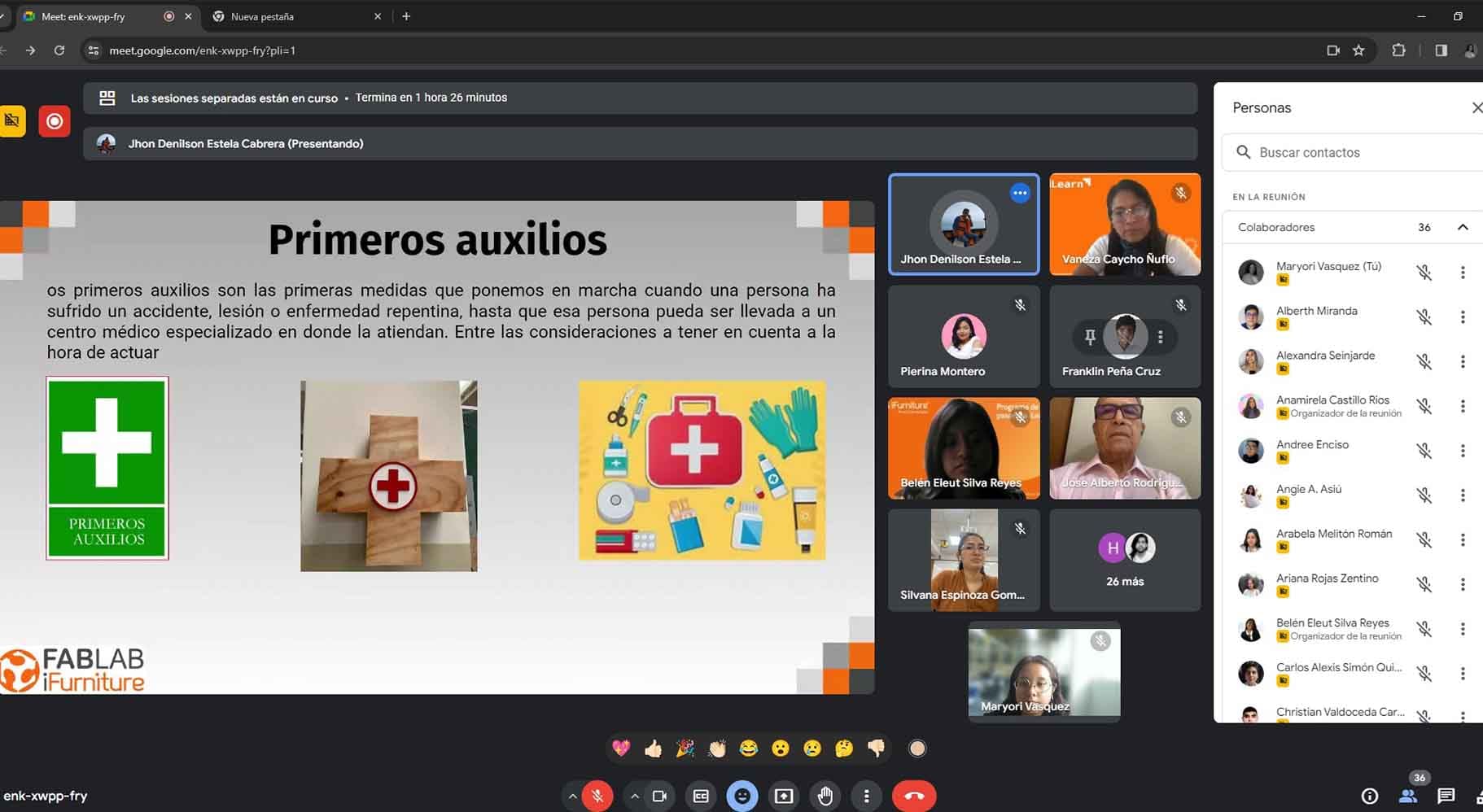
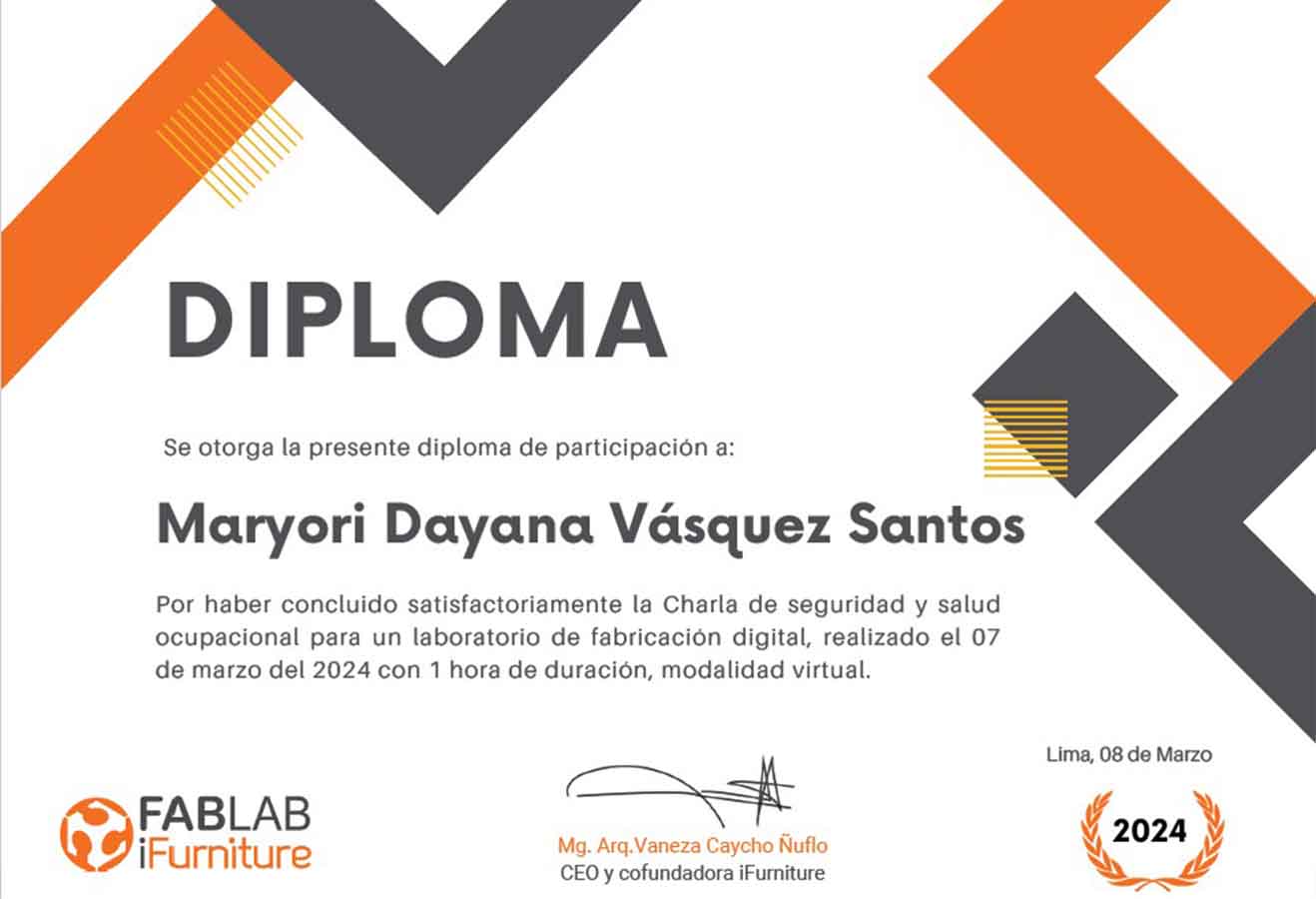
On Thursday 03 of this month, we conducted a virtual training organized by our local instructor Vaneza Caycho, this was on SAFETY AND HEALTH AT WORK, especially aimed at using the FAB LAB. We received previous and introductory recommendations about the use of tools, safety equipment, etc.
The speakers, safety specialists, told us the essentials before starting to use the FAB LAB tools, such as preventive signage to avoid accidents, as well as the use of "Personal Protective Equipment".
They also recommended that we should always have a plan of our laboratory space in order to locate safety zones, fire extinguishers, emergency lights, smoke detectors, etc.
Here is the final photo of all the participants, including me in this one.
To take into account:
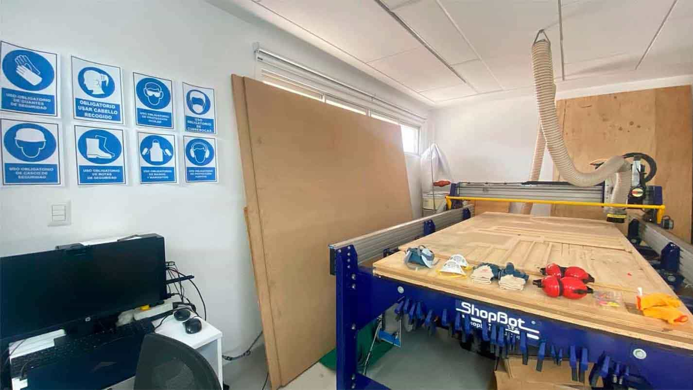
Our laboratory is in the process of habilitation, so little by little we are adding the safety components and equipment, with the intention of making it safe, our laboratory is located in Lima, at the Universidad Científica del Sur.
I also leave my certification in the safety course given by the laboratory iFurniture in "Safety and Health at Work".
Doing My Lab Safety!
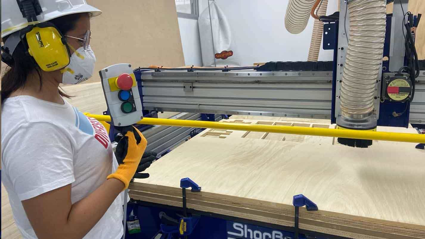
After the safety talk, I was able to coordinate with my colleague Hans, all the safety aspects to consider in our FAB LAB.
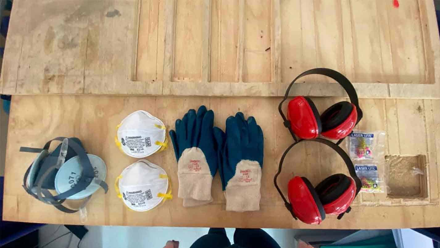
So we ordered our safety equipment and also checked if we had the respective signage, we were able to get it and place it in our workspace, I attach some pictures about it, as well as my person with the respective safety equipment.
Features, Configurations of CNC MILLING MACHINE
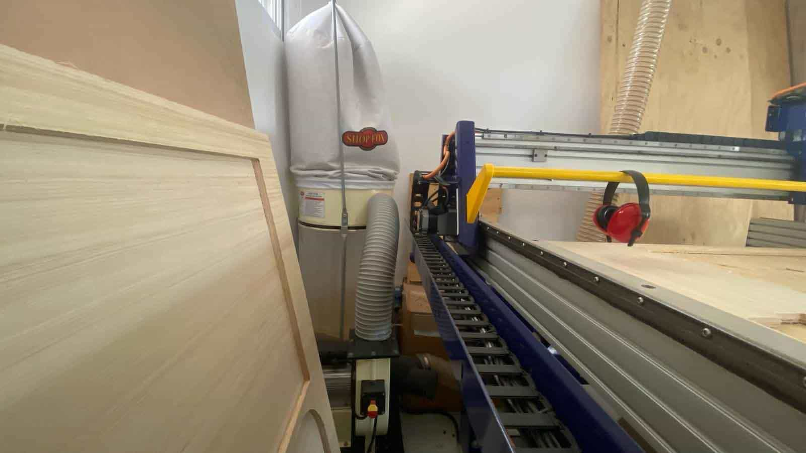
SHOP FOX DUST COLLECTOR
As an initial recognition, the CNC parts are identified, such as the chip and dust collector, which has its own power switcher and direct power port.
AIR SUCTION CAPACITY:
1.550 CFM/td>
STATIC PRESSURE:
12,3 inches
STANDARD BAG FILTRATION
2.5 microns
MOTOR AMPLIFIER POWER:
220-Volt - 12A
BAG VOLUME:
5.4 cubic feet
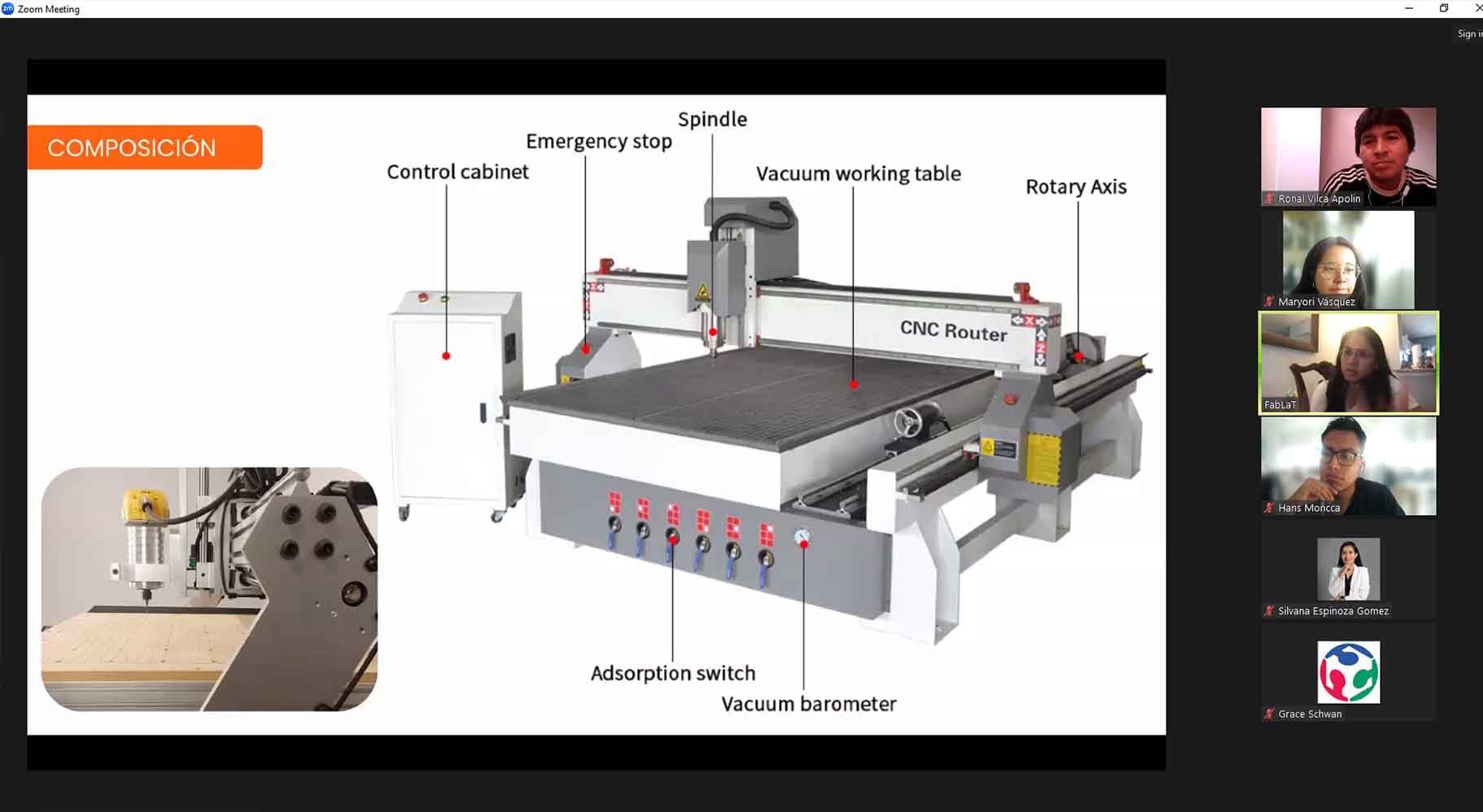
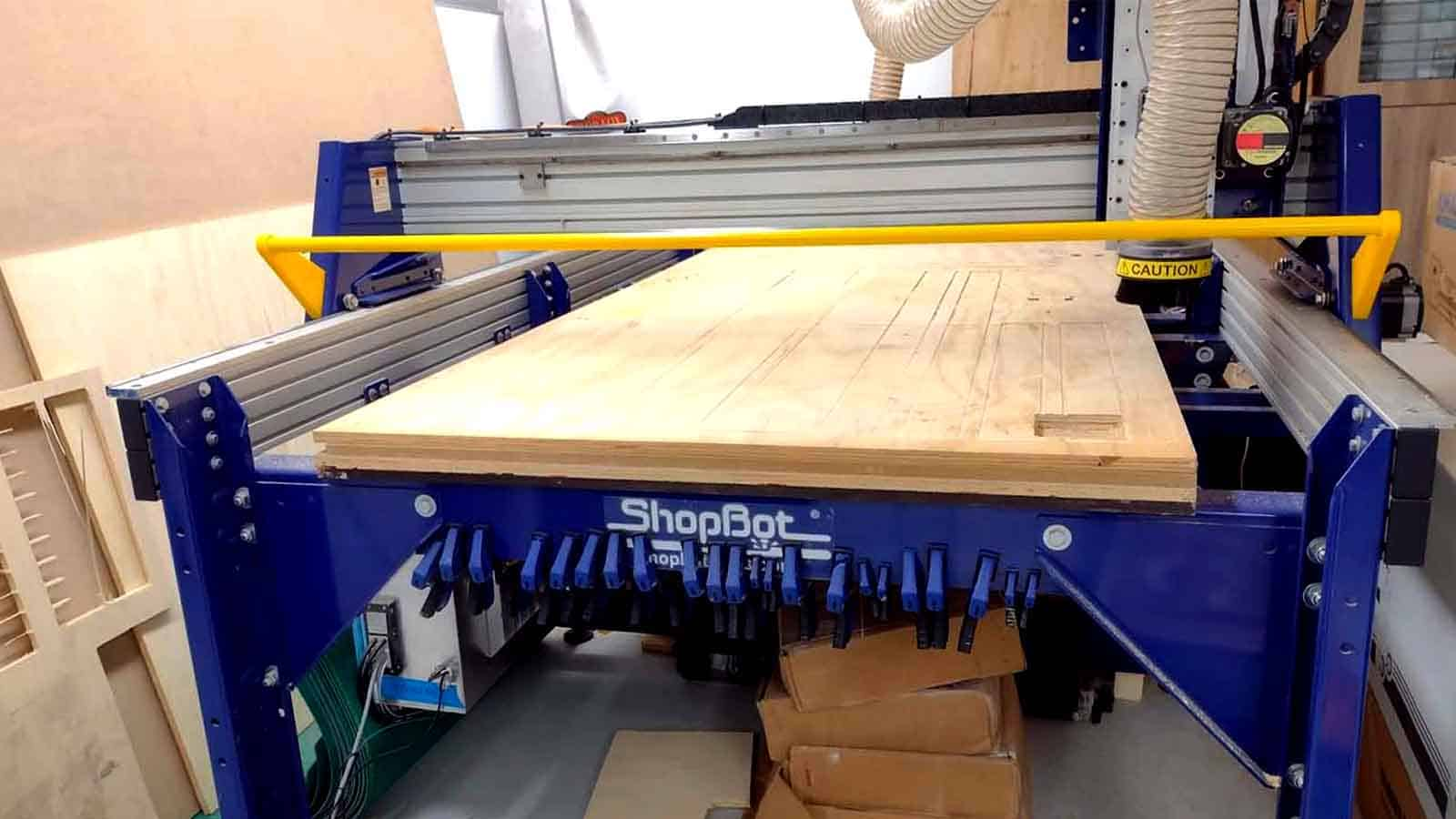
SHOPBOT PR-ALPHA
The CNC router machine that we have at the Universidad Cientifica del Sur is the SHOPBOT PR ALPHA MODEL 96 - 48, which has the following technical specifications:
CUT / MOVEMENT AREA:
105” x 61” x 8”
XY POSITIONING SPEED:
Variable, max. 1800”/min.
Z POSITIONING SPEED:
Variable, max. 900”/min.
LINEAR CUTTING FORCE:
Approximately 150 lbs.
INPUT VOLTAGE:
220v single-phase, 230v 3-phase and 380/460V 3-phase power options are available, depending on tool and configuration.
A brief important reminder
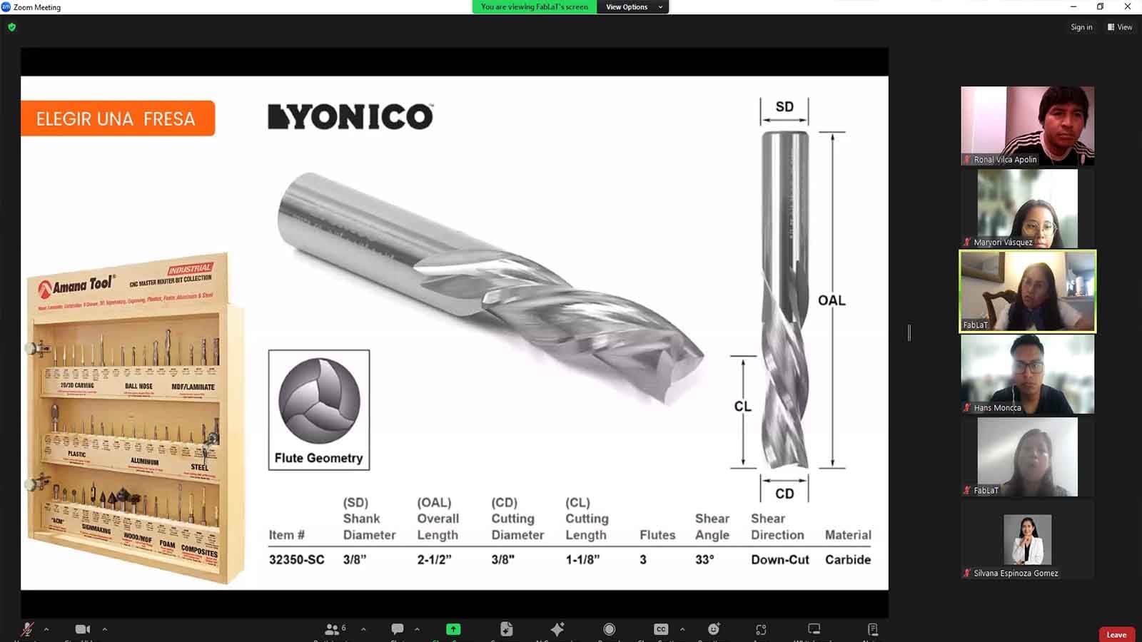
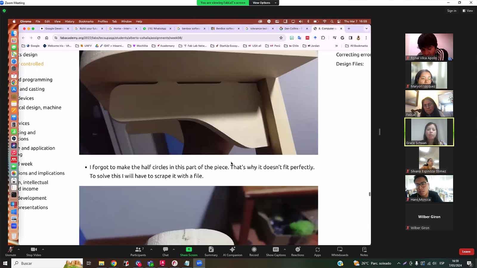
We had the pleasure of conducting another introductory training on the use of the CNC, its components, specialized functions, mode of operation, type of milling cutters, basic concepts about the tools that can be added to the CNC, etc.
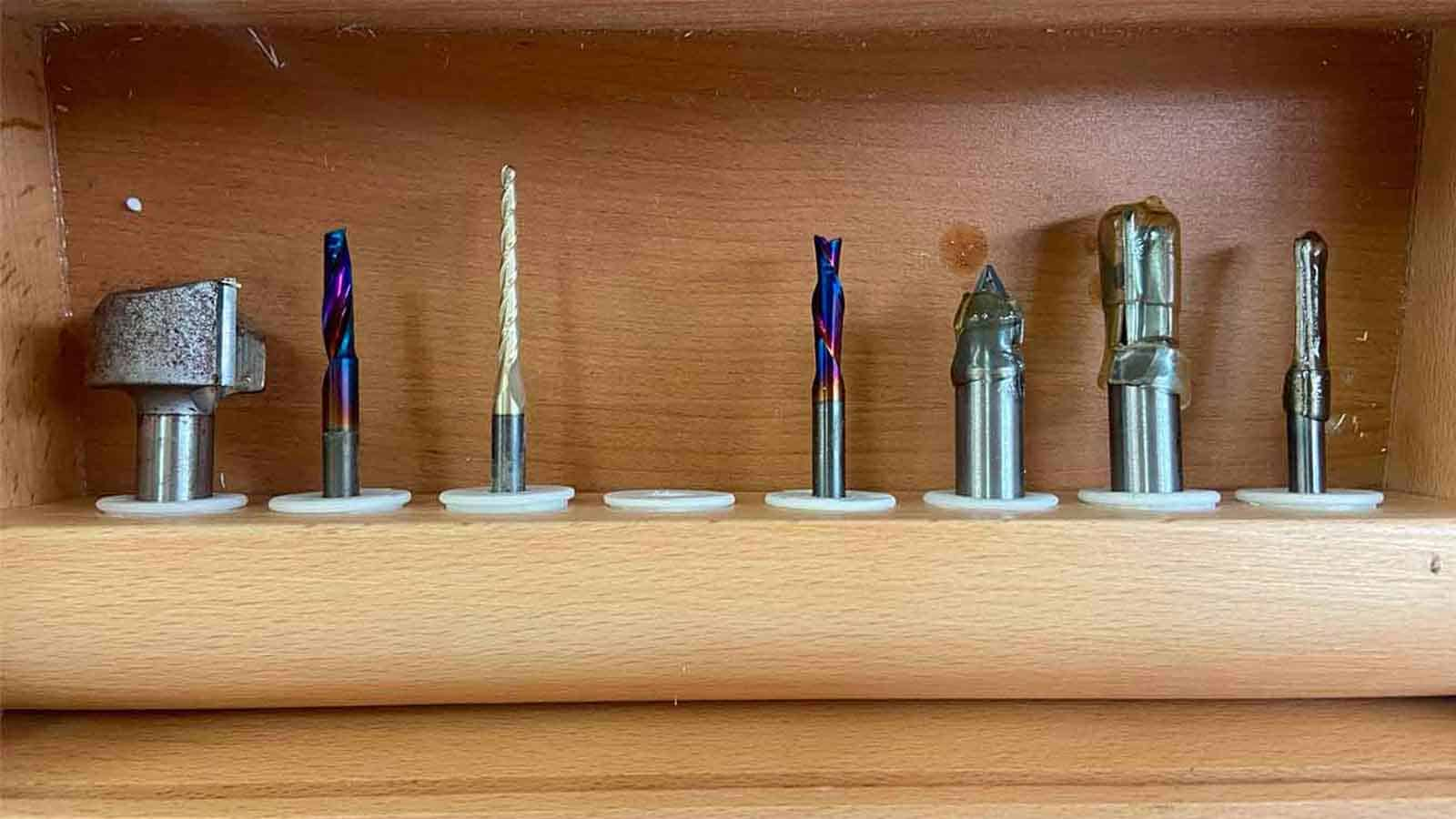
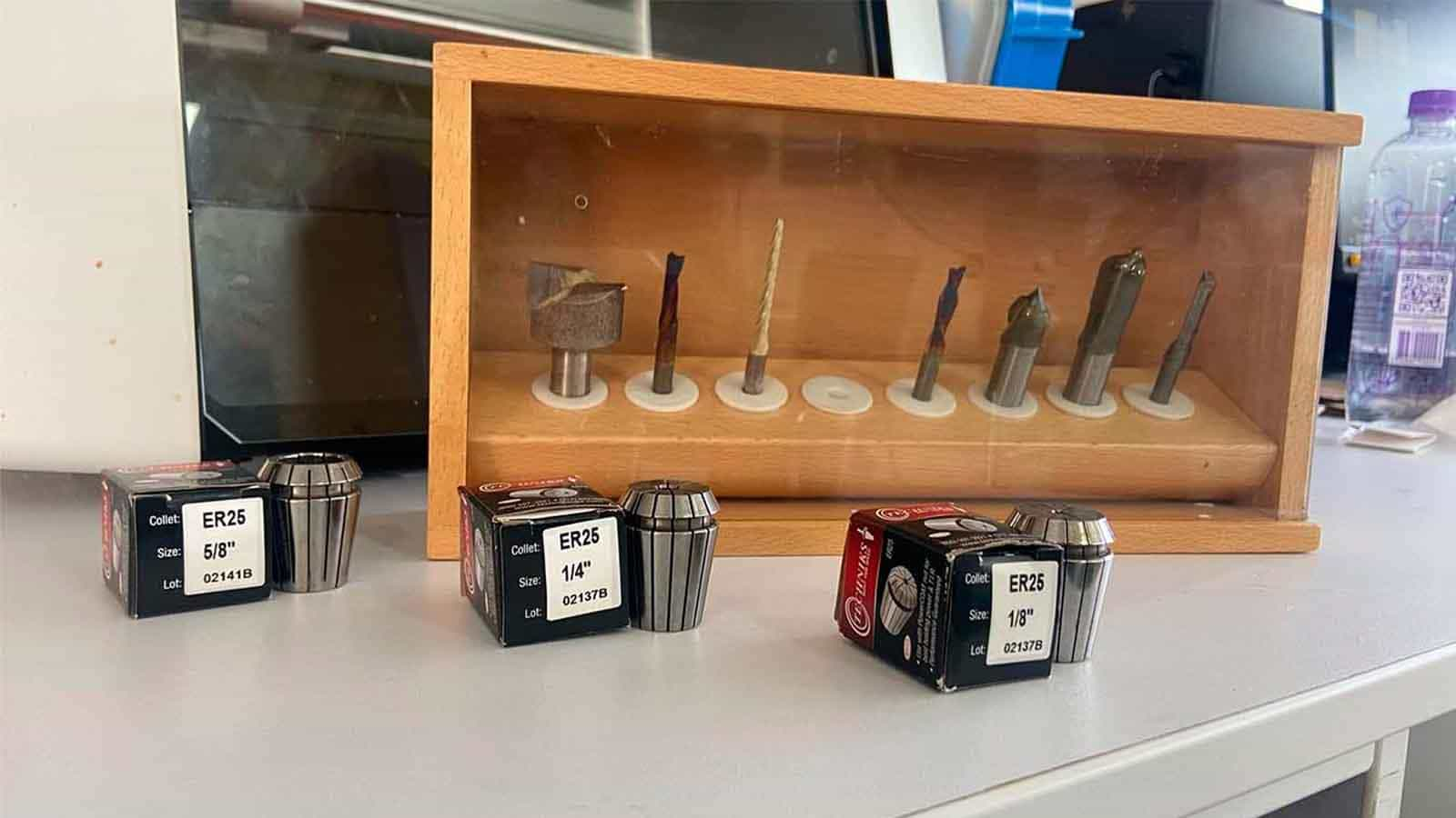
What do we have in our Laboratory?
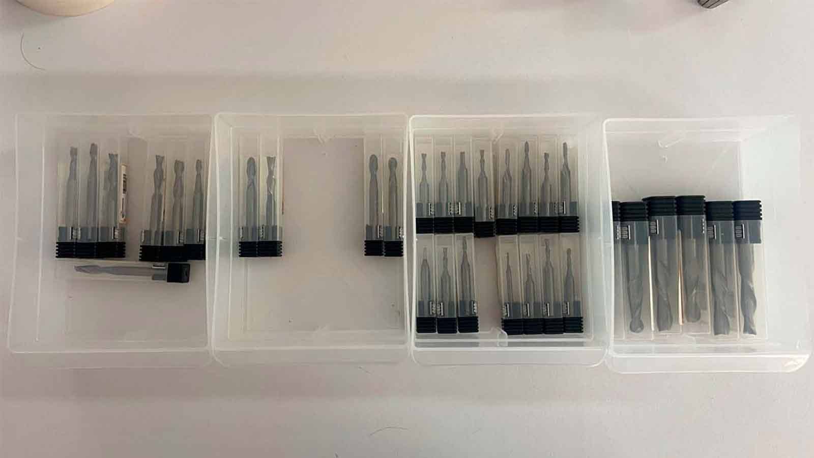
The following attachments are in stock:
- 1/4", 1/8" and 5/8" milling cutters along with their Spring Collet ER25 and in addition to that, theSHOPBOT.
- For our group and individual jobs we will use the 1/4" milling cutters, along with their corresponding collet as we have many more spares in case we have any problems and we can get the job done.
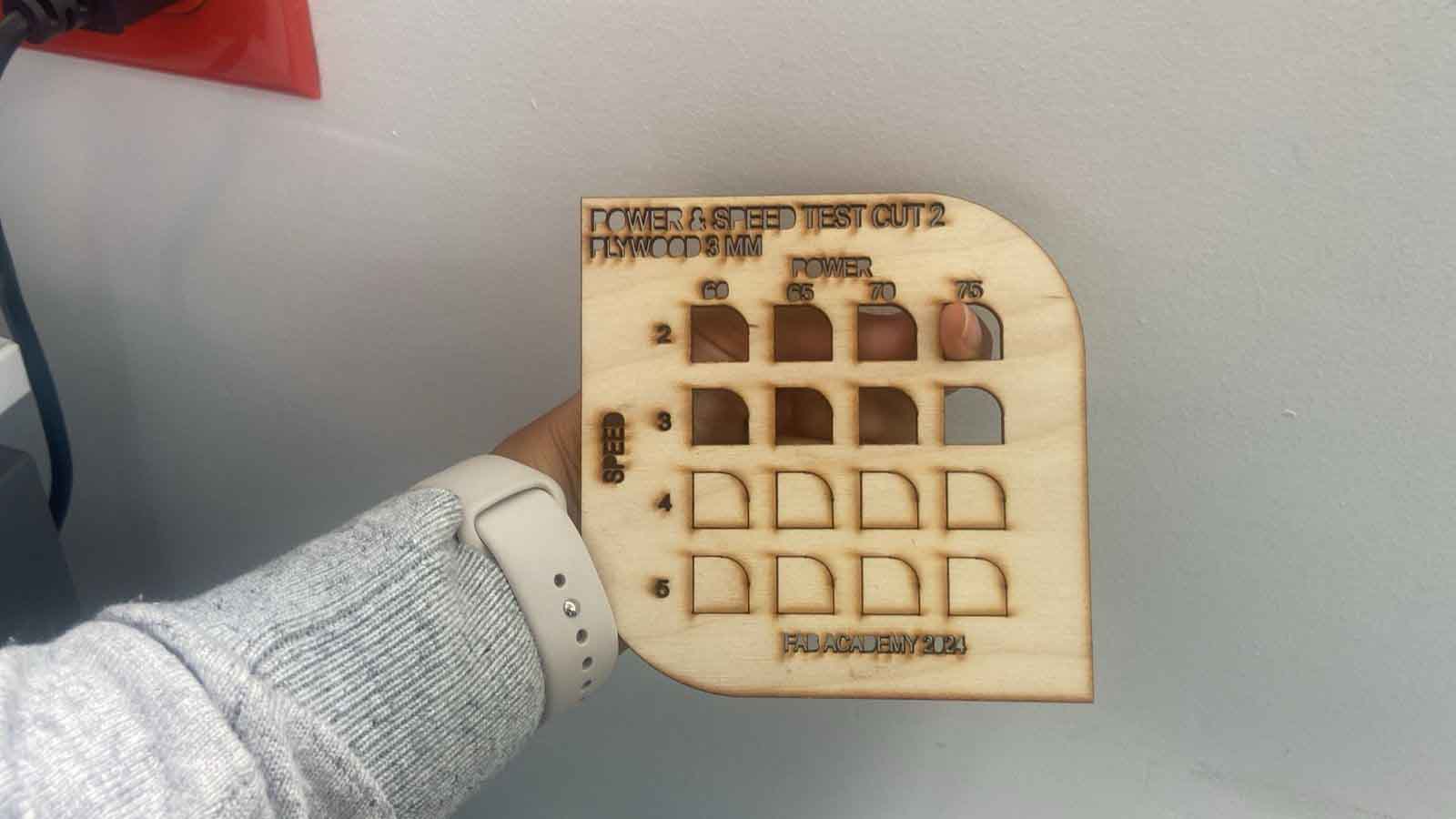
The Test: RUNOUT, ALIGNMENT, FIXTURING, SPEEDS, FEEDS, MATERIALS AND TOOLPATHS FOR YOUR MACHINE
The Comb
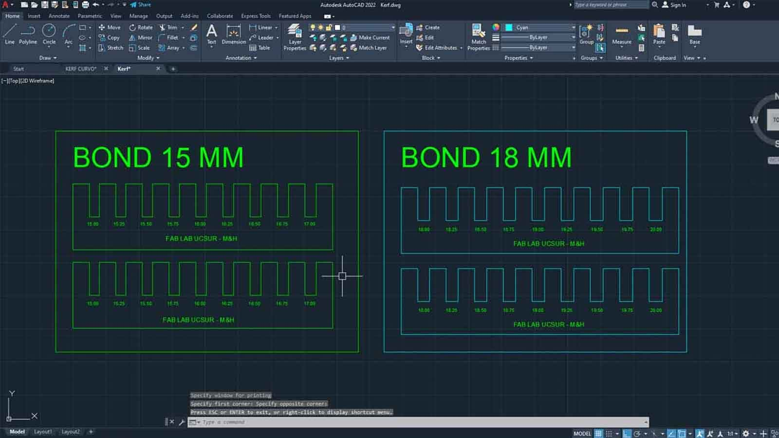
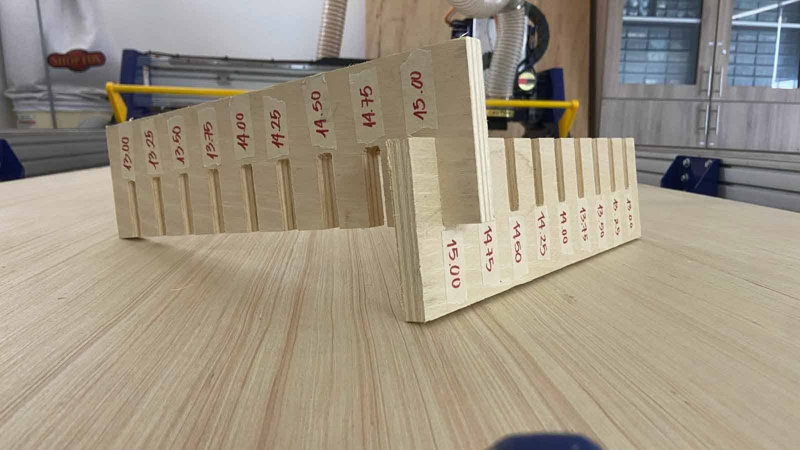
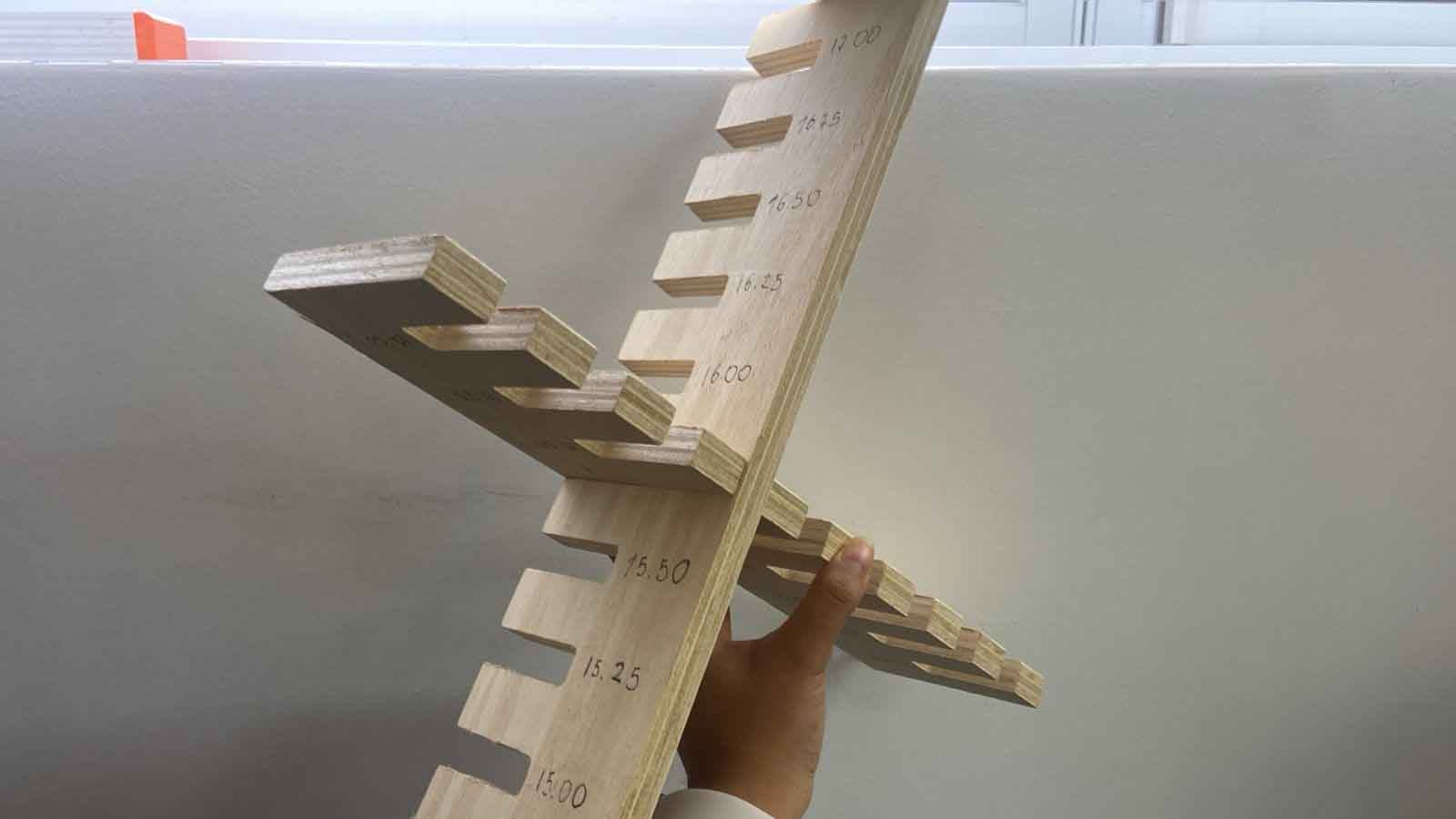
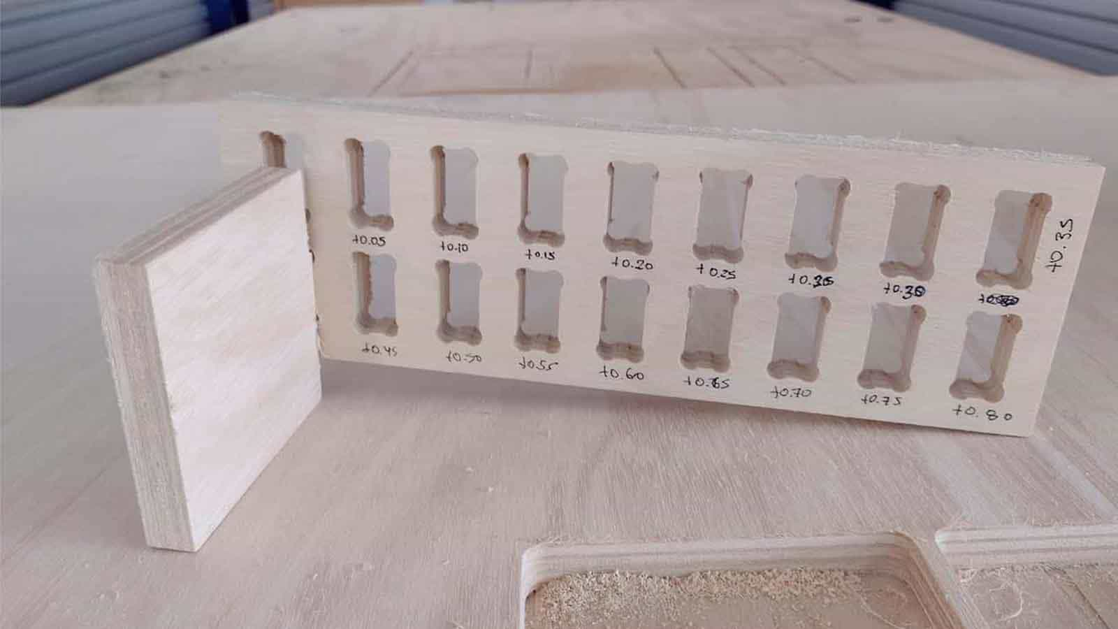
The first test is the COMB, the intention is to find the most secure fit. We use the material: Plywood of 15mm, the same that will be used for my individual project.
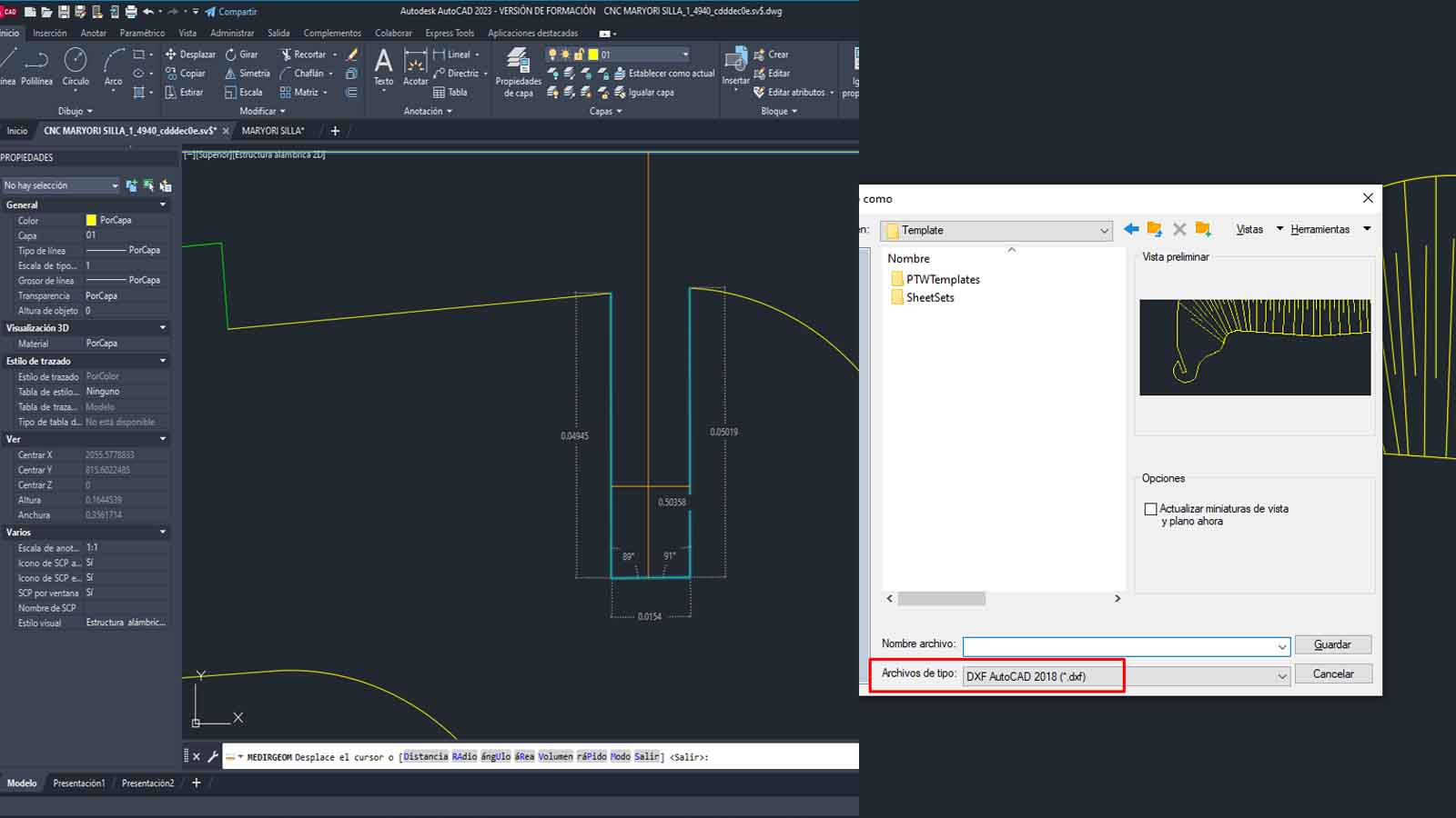
We use the drawing in AUTOCAD and export in DXF, so that the CAM program can read it, it is worth mentioning that in the drawing we have chosen values between +0.25mm for each socket; here some pictures of the process:
Here some points to consider in the CAM configuration
NUMBER OF PASES:
3
SPLINDE SPEED:
18000 RPM
RATE:
5000 mm/min
CHIP LOAD:
0.1389 mm
CUTTING AREA:
OUTSIDE
The first mistake, we worked the COMB with a wrong measurement and values less than 15mm, we certainly thought we were right but we verified that no value fit.
After verifying the measurements again, we modify it with the value of +0.25mm as indicated above, the best fit is 15.40mm, we stay with this!
A video when the CNC made the cut
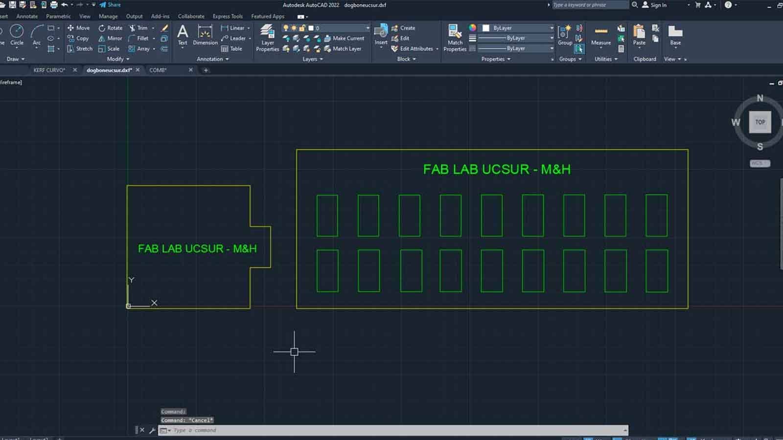
Dog Bone and Hole Test
The second test is the dog bone and the hole. The idea of the test is to know what size is needed for the pieces to fit well in the holes.
The DOG BONE test is to make it easier for us to insert the pieces between them and to ensure that the corners do not have problems, this mainly applies to the FEMALE pieces. On the other hand, the hole test is to know what size the female piece will be so that the MALE piece can enter without problems and without damaging the material.
On V-Carve:
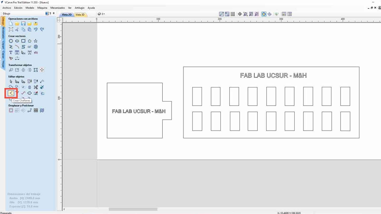
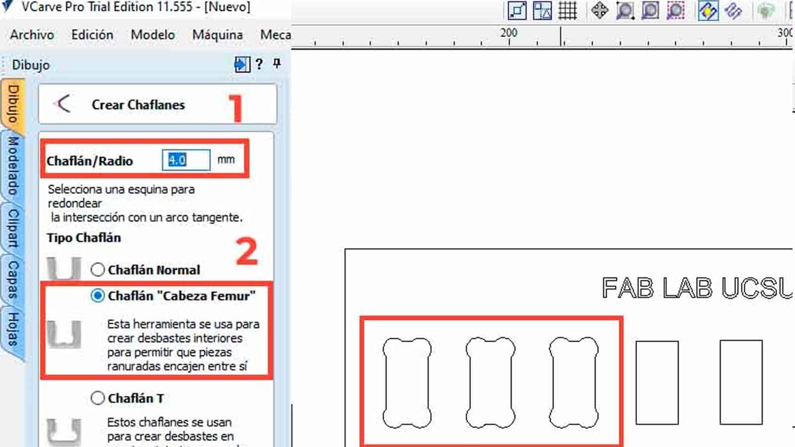
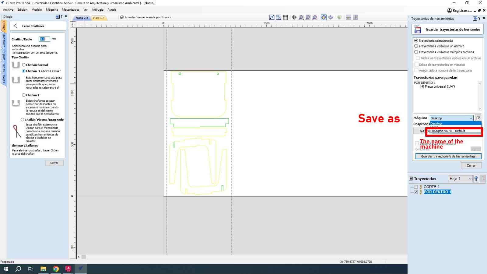
To give the DOG BONE shape, we can do this in the VCARVE PRO after having the pieces designed. When importing, we go to the CREATE CHANFLES button.
After modifying all the holes in the imported file and sending it to be cut, we can see the difference and this process is important so as not to damage the materials and the pieces fit better. Here I leave the table of the characteristics taken in the VCARVE for the cut and the cut piece.
NUMBER OF PASES:
3
SPLINDE SPEED:
18000 RPM
RATE:
5000 mm/min
CHIP LOAD:
0.1389 mm
CUTTING AREA:
INSIDE
In the following image we can see that the MALE piece easily fits into the +0.40mm hole, that is, if the piece has a thickness of 15 mm, we need the female piece to have a hole of +0.40mm, in this case 15.40mm. And we add this same calculation to the height of the female piece, in order to obtain a suitable female piece and we can have a perfect fit, without the male piece entering with too much force or coming out easily. For this the test helps us a lot.
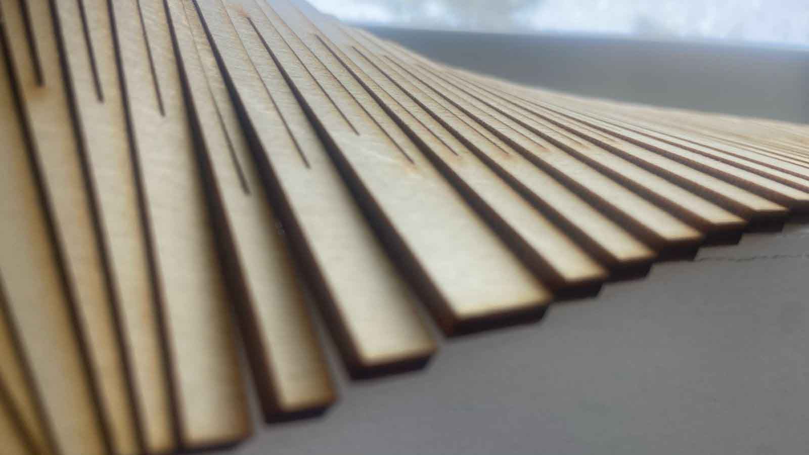
Flexible Woods
Curiosities of shape and something more
The Tests
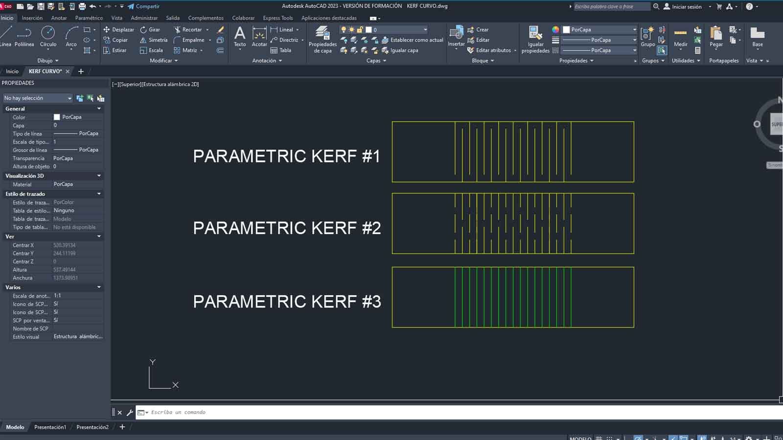
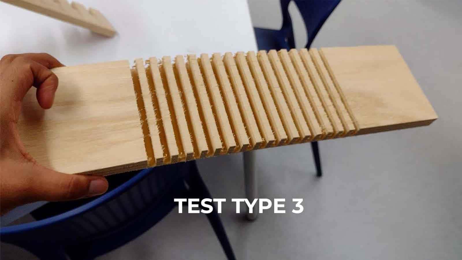
A search for flexible patterns is carried out based on the kerf of the laser cut pattern cut in the third week of the Academy, where through various shapes we can see the difference between geometric flexible movements and other more organic ones, we call this Flexible Woods and I wanted to represent it in the following way
The 3 patterns contain segment lines that are not drawn with thickness, since in the CAM the cut "on the line" will be used, so that the passage of the tool over the material is in greater detail and allows the minimum distance to show the flex
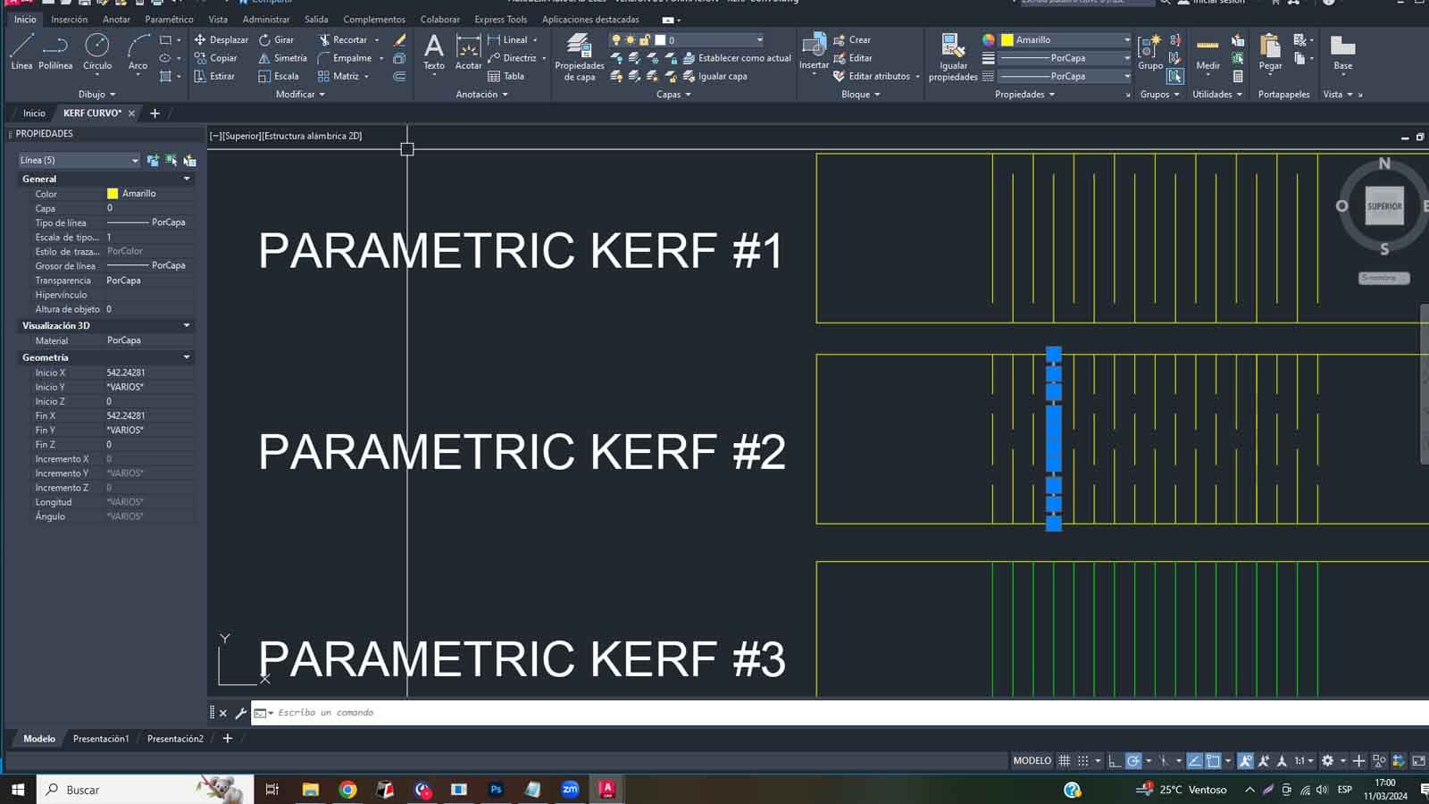
On the V-Carve:
After importing the pattern in DXF, joining the lines from the work canvas, the file is worked in 2 parts or routes:
1. The first is for cutting "OVER" the bend lines of the flex, this must be exported as a separate file from the cut paths.
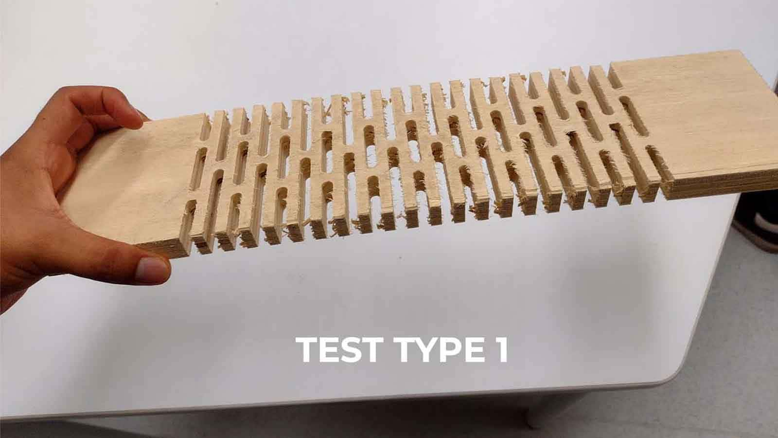
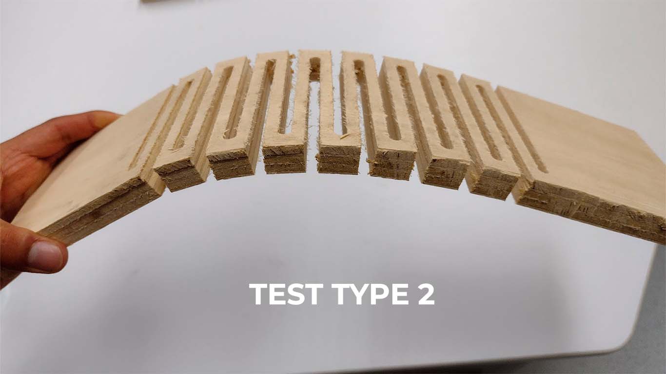
For tests type 1 and 2, we have to make the drill cut above the line, so we will choose OVER THE LINE, where the drill will pass through the designed lines that have a separation of 12 mm.
Some Results:
There is some results of the cut in the CNC, you can see, everything is ok, so I put it to the test.
What's the problem?
A few lines in Autocad made the mistake more big than I think, that's because you import this to V-Carve, yo can't modificated in that software, so, the problem drag on the final result and the cut too.
So, I cut again and this is the final result:
Individual Assignment
An application Tested
The result!
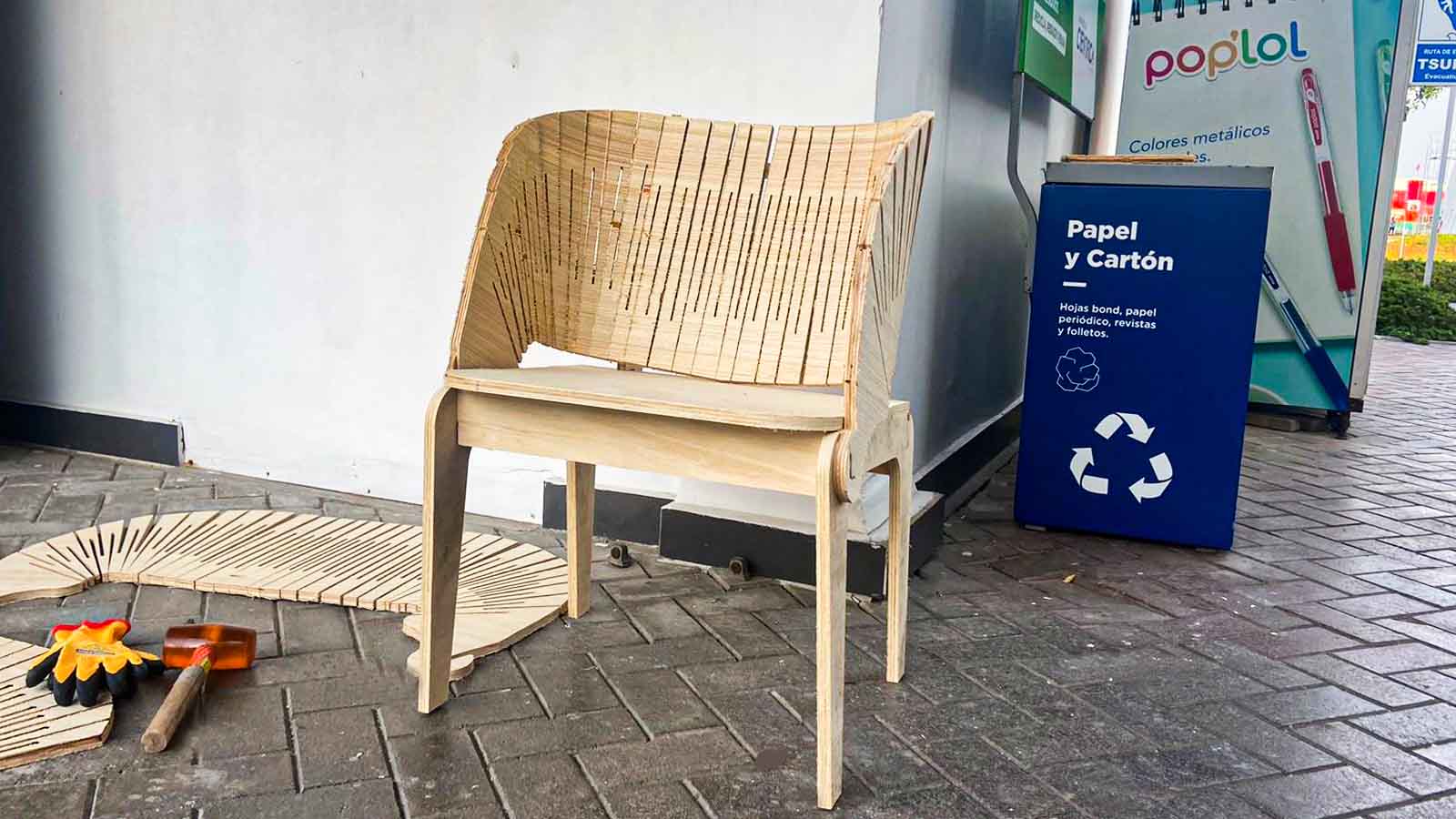
After testing the Flexible Wood textures, I ventured to make for my Assignment Individual, the development of a chair with a flexible texture as a backrest, here is a sample of what I wanted to achieve and it was achieved.
First sketches
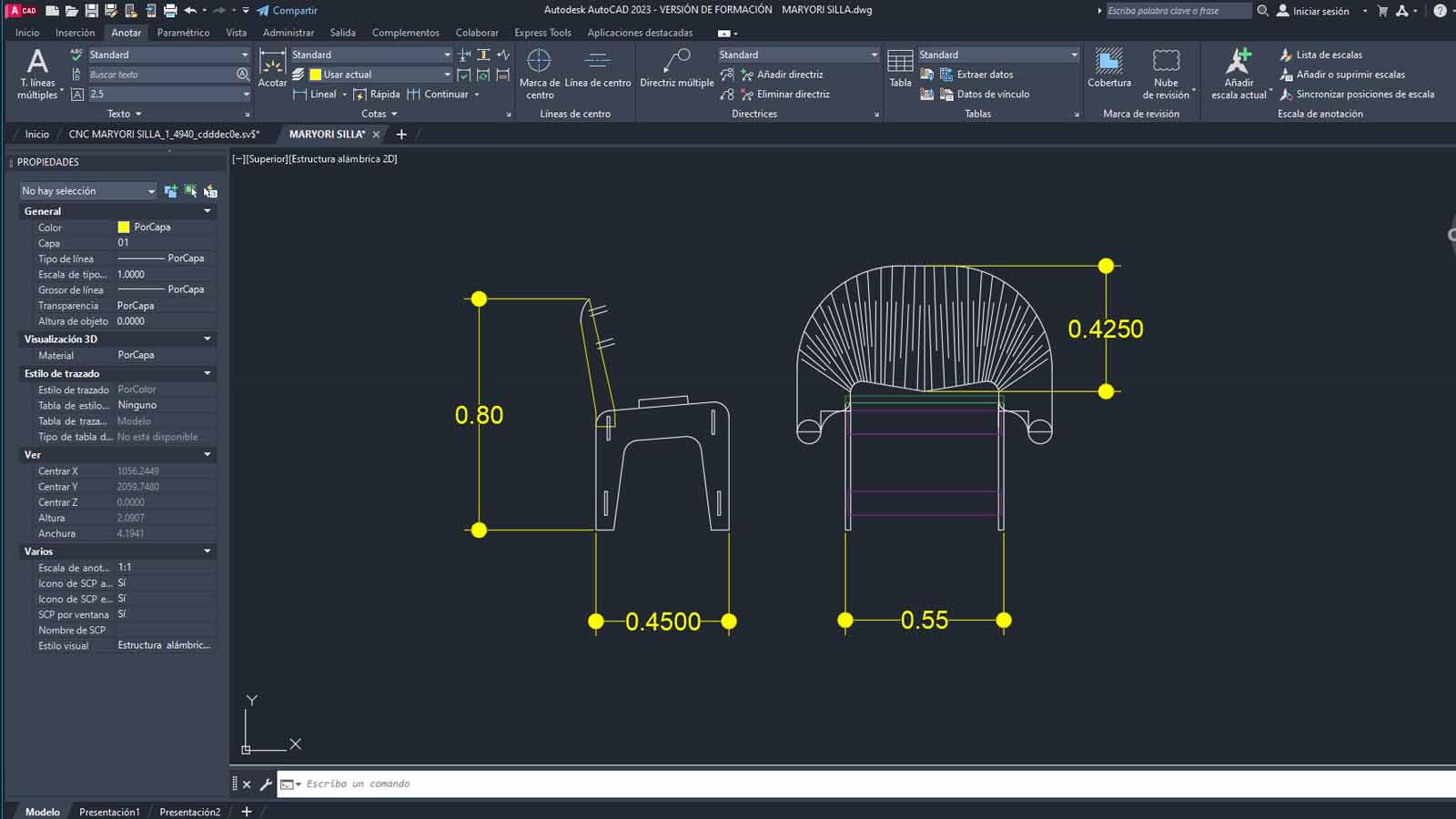
I develop first general sketches of the shape and how I want to achieve the fittings, plus some ergonomic details to achieve comfort in the user, I leave the measurements of my object here:
After verifying the measurements correctly, it finally looks like this:
Seat height:
0.45m
Backrest height:
0.425m
Seat width:
0.45m
Total height of chair:
0.80m
It should be noted that this chair is of the outdoor armchair category, so it is a little lower than normal, but it works exceptionally well for desks, dining tables, etc.
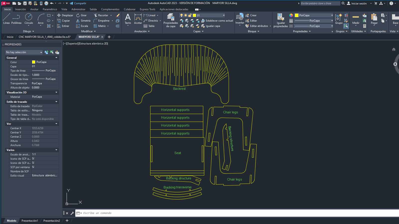
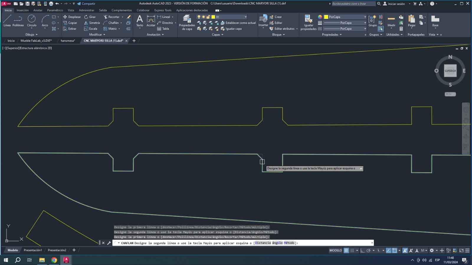
As a first step, AutoCAD is used to draw what was done by hand, converting it to measurements is not complicated but we must consider basic anthropometry to see that it works.
The Laser Test
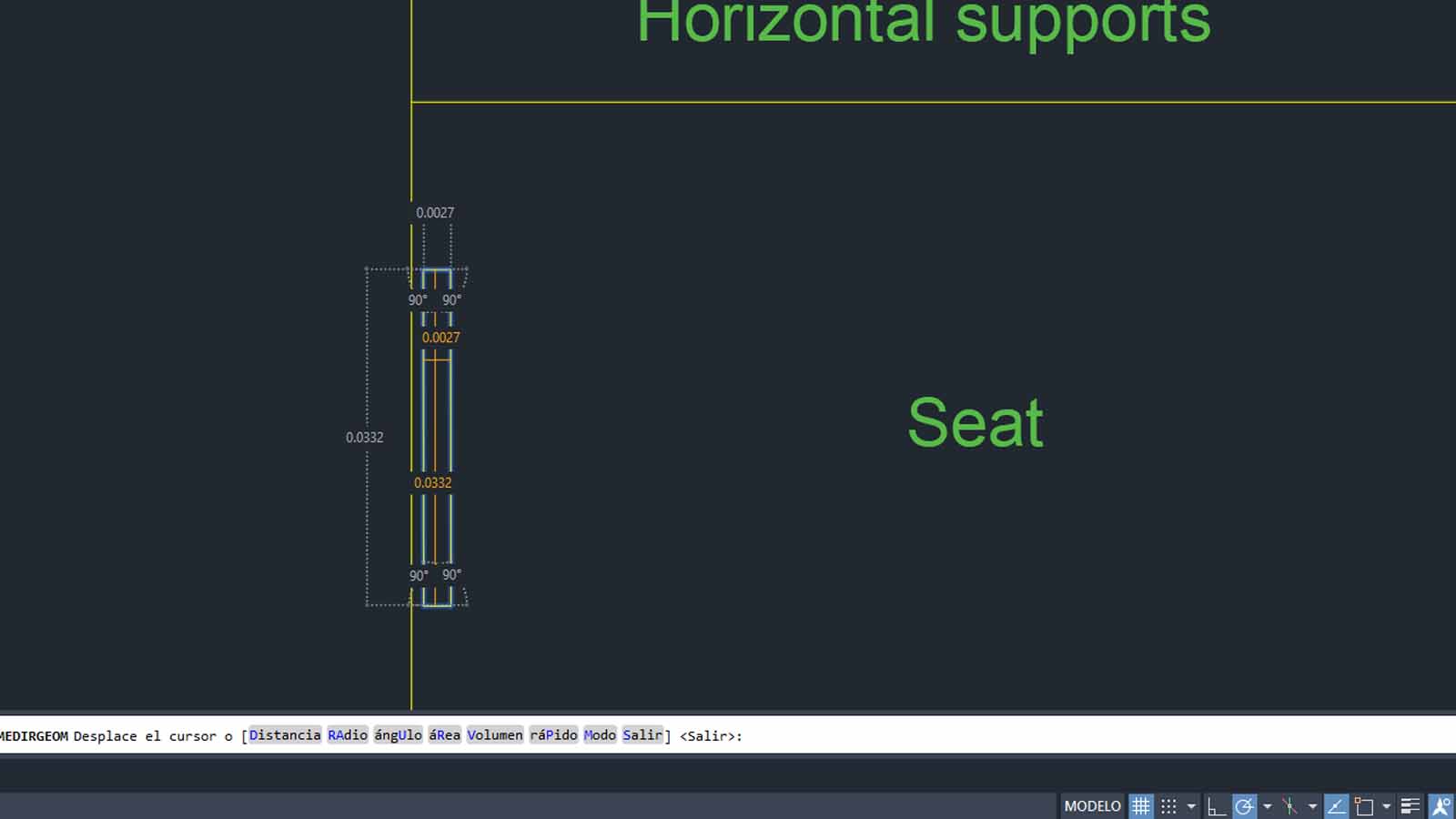
We can verify that the couplings are not yet fully defined and it is because they will be tested in 3mm PLYWOOD to check the stability of the backing, so the sockets are 2.75mm for each piece, I point it out from this exploded image
Consider the recesses for the 3mm plywood, a more detailed view is attached.
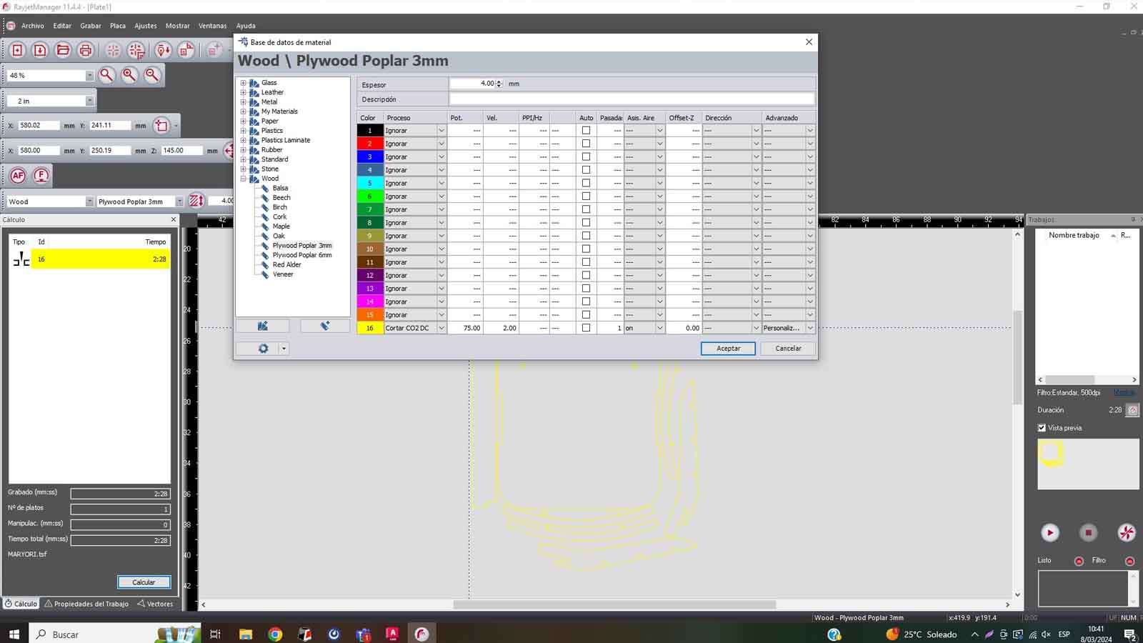
Before laser cutting, we export to the R500 Rayjet program and determine the following parameters:
SPEDD: 75
POWER: 2
To make the cut not so burnt and to make it come out correctly, I used my previous laser tests to help me.
Doing the laser cut and assembling:
RESULTS:
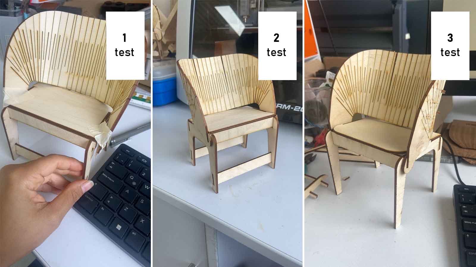
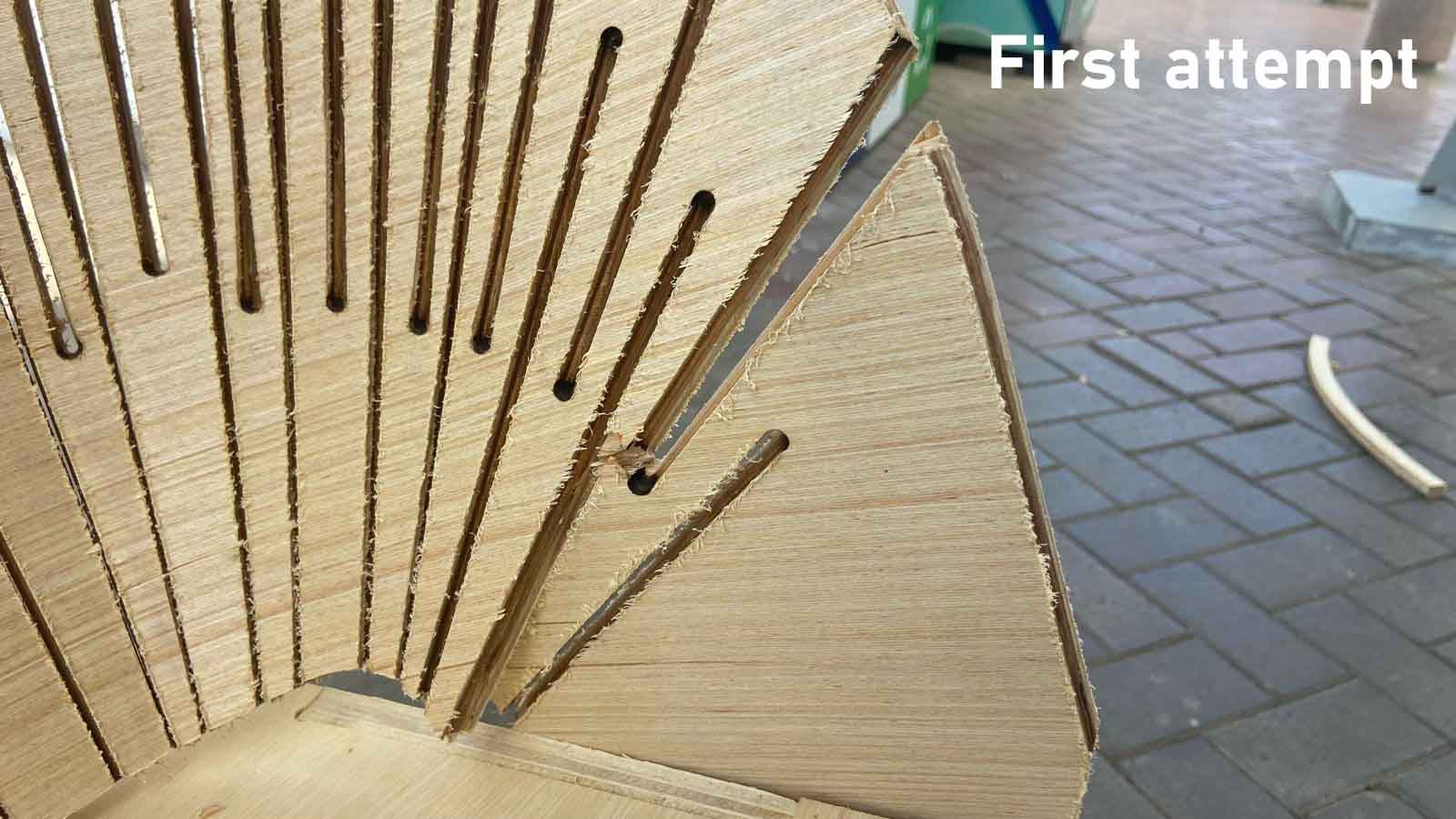
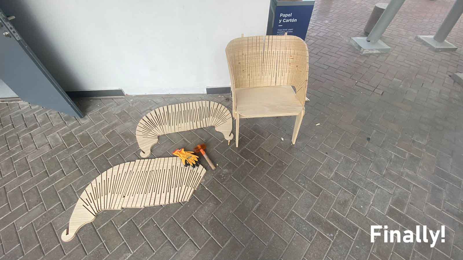
After making the first cut, I found several flaws, I detail them:
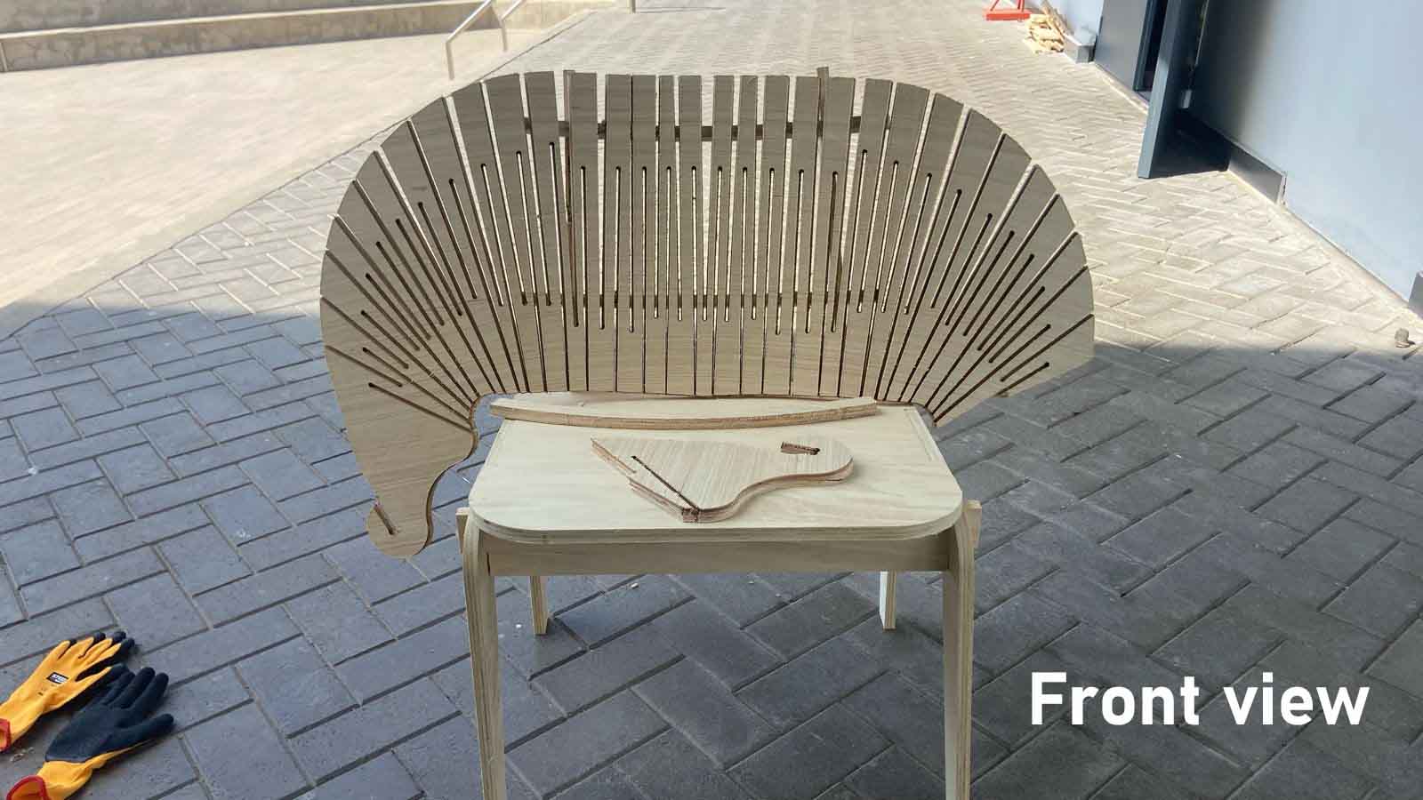
First Test: The seat and legs are very secure, but the backrest is loose because it has no way to hold on the base, in the first test the backrest breaks, in the drawing a line was poorly drawn.
Second Test: In this attempt the flex of the parts can be better realized but the ends of the backing can hardly be attached to the base, so one last test is made.
Third Test: From this test I was able to correct the fit of the backing on the base structure, in the video you can better understand how the pieces work and how they are more stable.
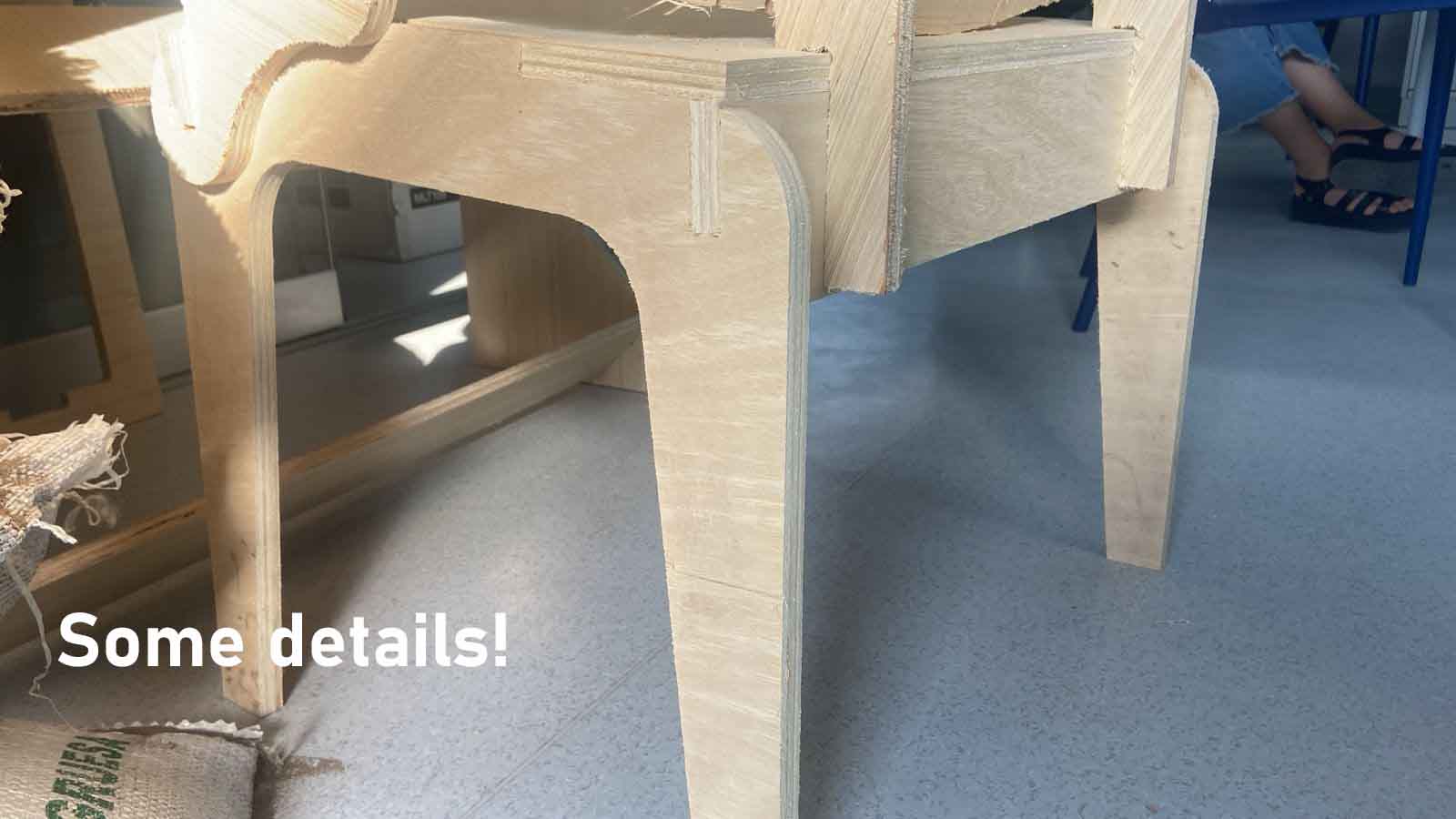
A little closer:
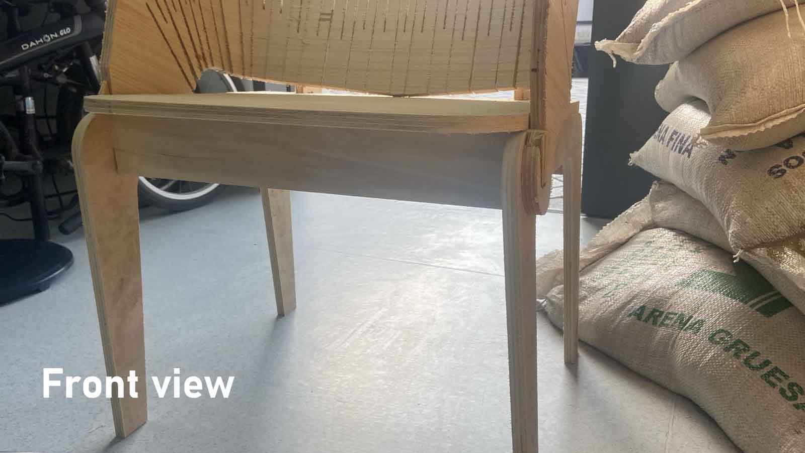
The 3 tests:
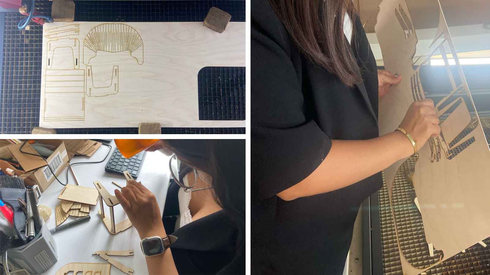
Moving to CNC
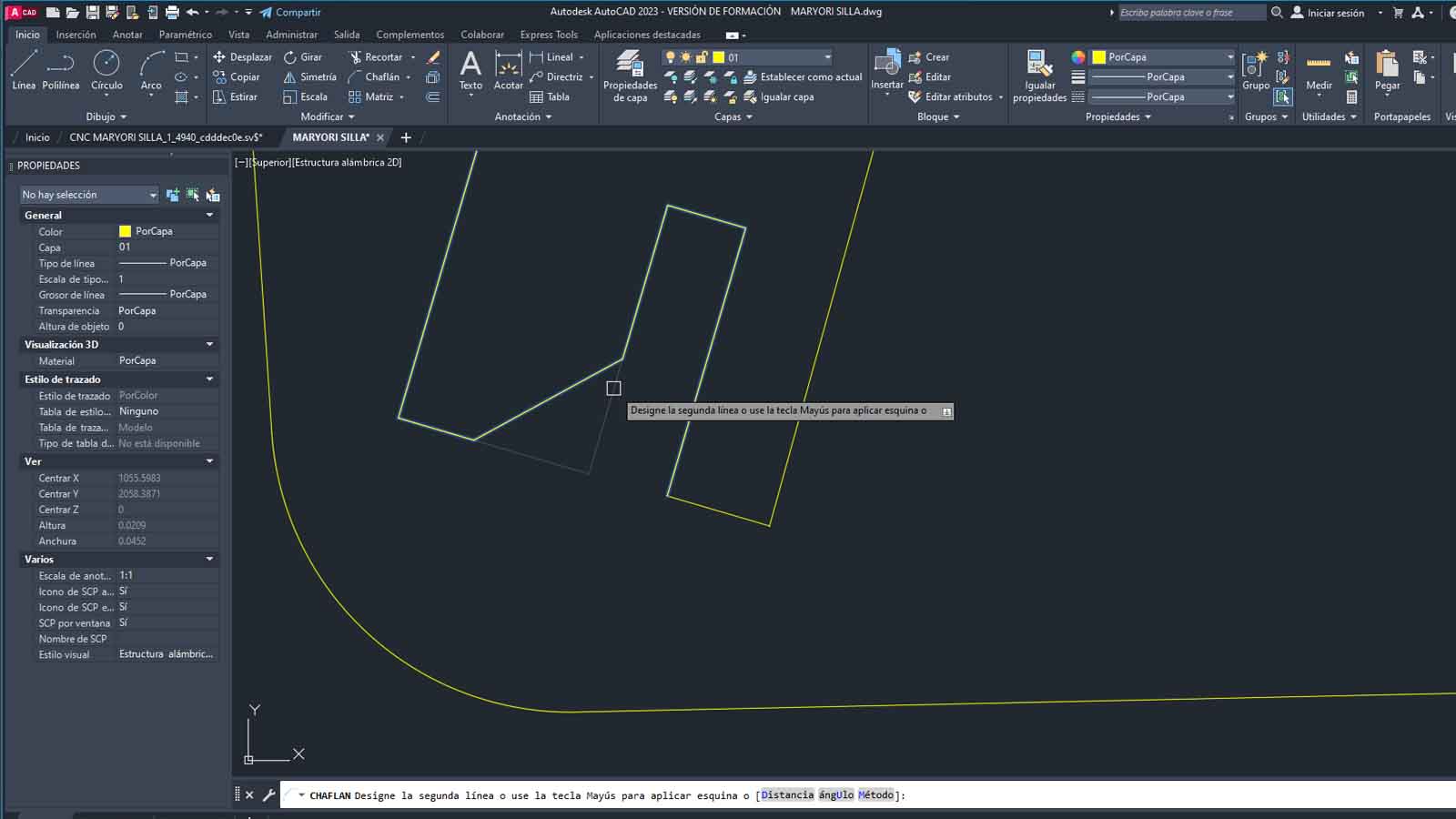
For the configurations on the CNC drawing, it is necessary to export the parts in DXF for the V-Carve software, considering that before passing to this part it was necessary to make the joints according to the tests carried out, determining that 15.4mm will be the joints between two parts.
For the sockets I left a 4mm CHAMFLER for when the pieces are connected to each other.
Also, it is important to save material, since the designed pieces were placed on leftover scraps from previous cuts.
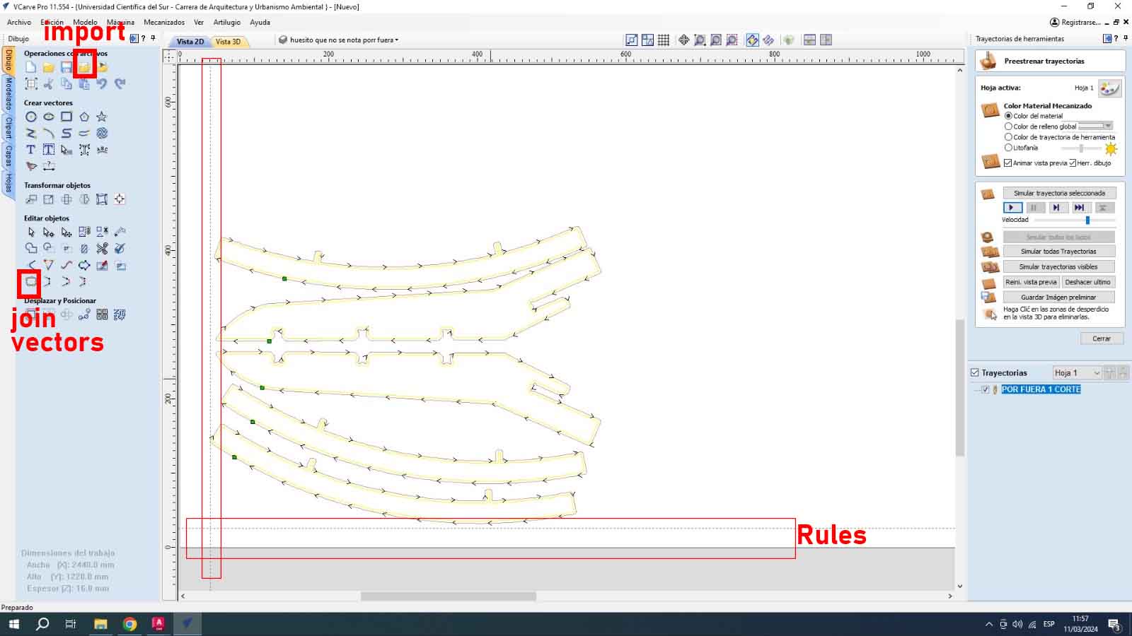
Switching to V-Carve
We start importing our DXF file to V-Carve Pro, considering that our drawing is centered on the working canvas, I recommend positioning GUIDELINES or RULES to leave some margin on the plate and that the milling cutter does not pass so close to the edge and by force can move or break the fasteners.
After joining the vectors and positioning the drawing on the rulers, I create the paths. For the first group of cuts (seat, legs) I divided the cut into two parts:
1. Cut Inside
2. Cut Outside
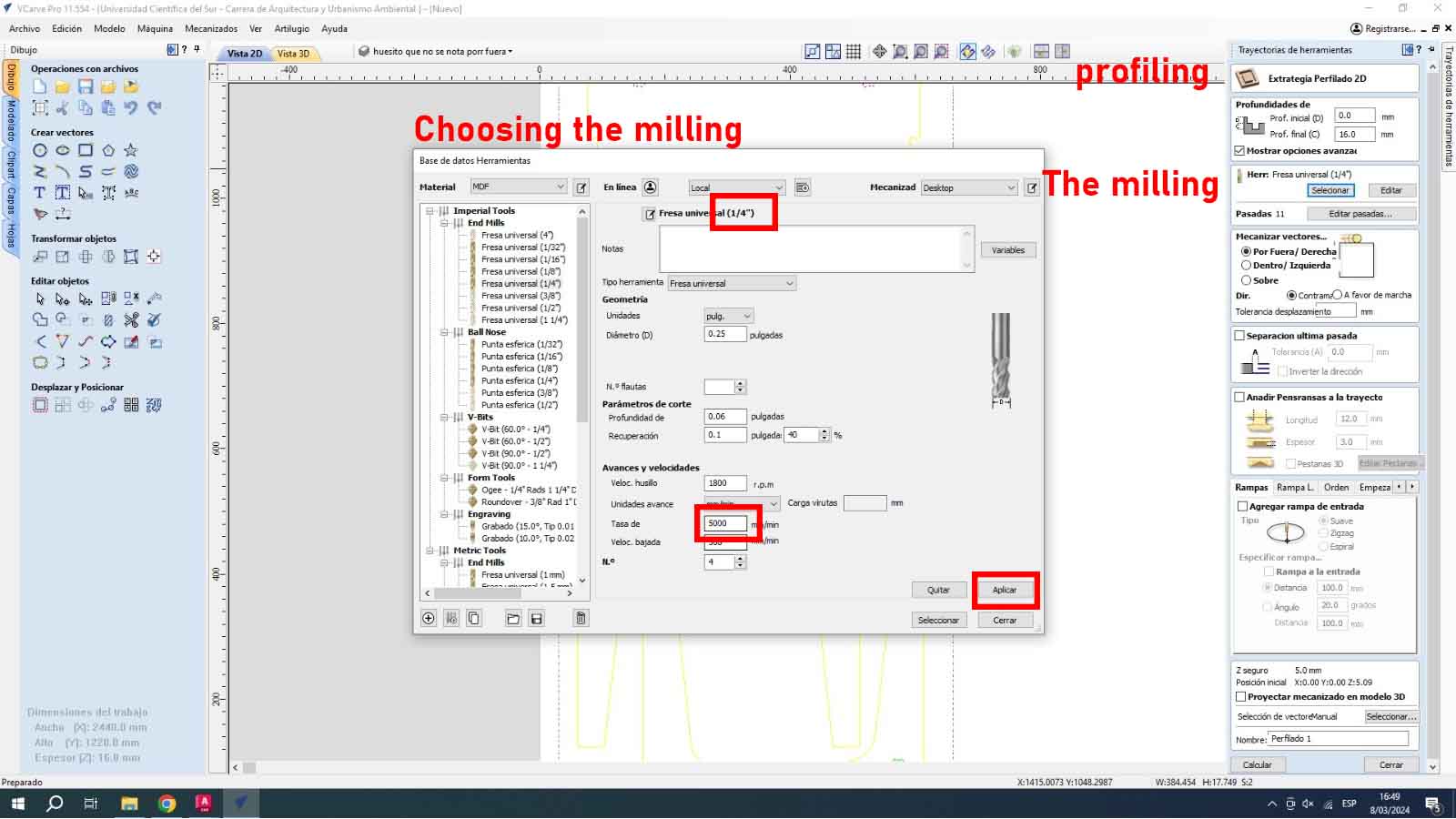
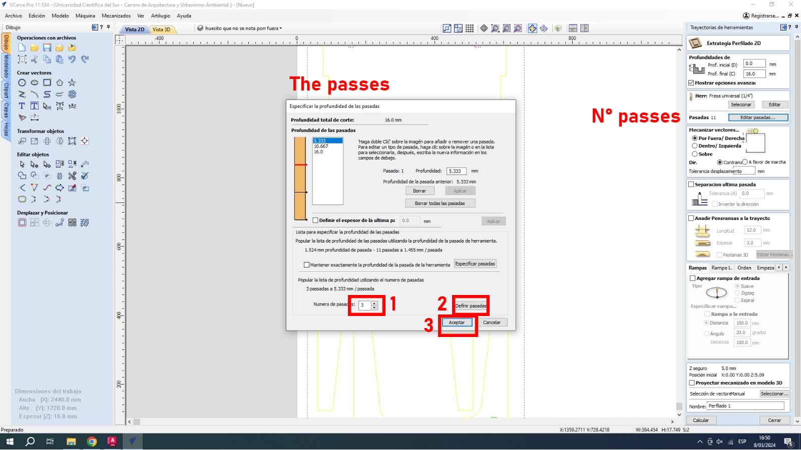
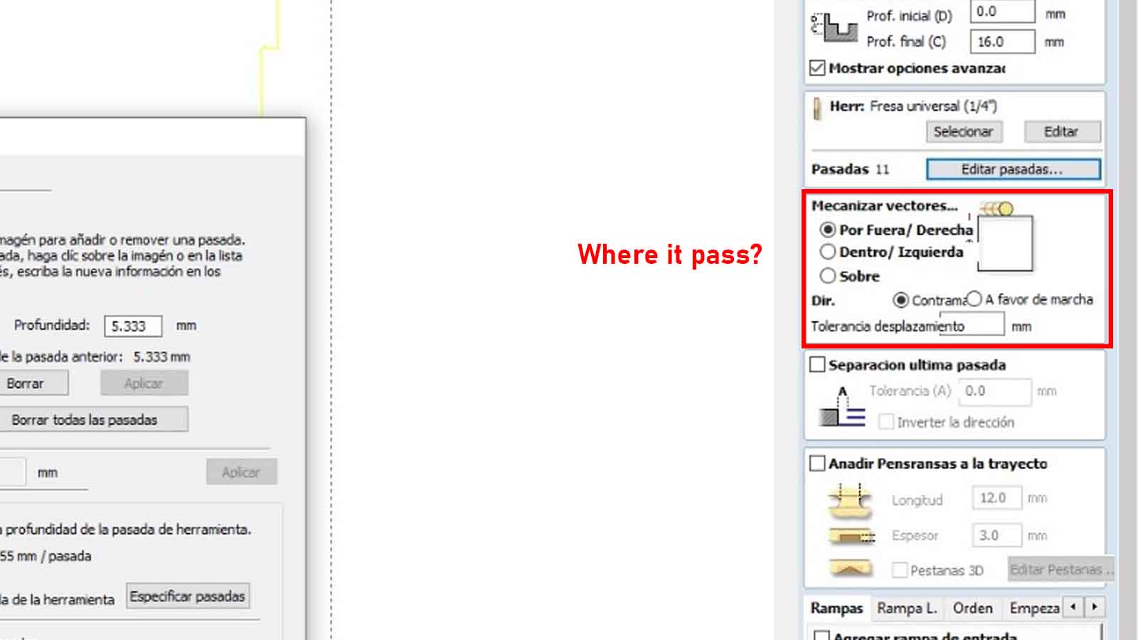
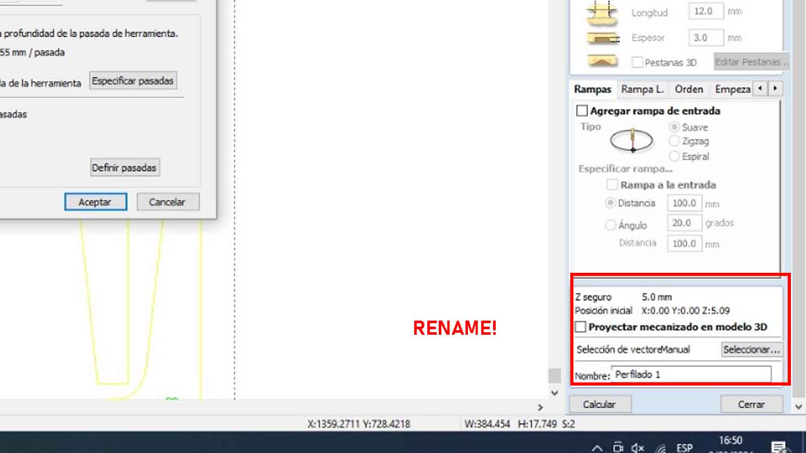
To do this, first I must select the vectors that I want to cut inside, then I select the cutting tool and set up:
a. The type of cutter
b. The passes for cutting and definition
c. Where the cut passes through (over, inside, outside).
d. Renaming and waxing
e. Preview the cut
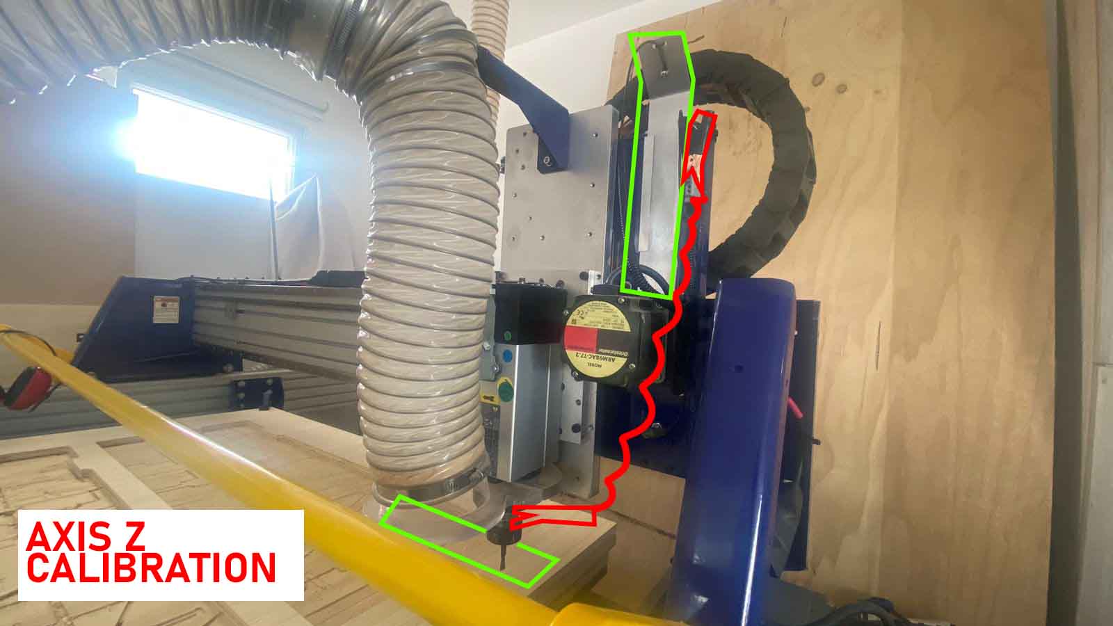
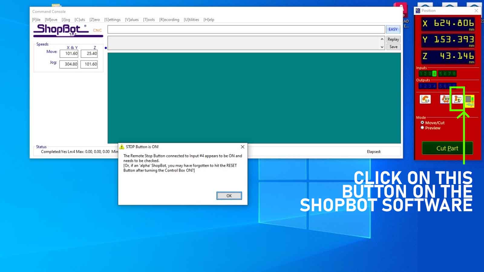
Calibrating the CNC
To calibrate the CNC, we first perform the calibration of the Z axis, taking into account that the safety head must be removed and with the side key off, the video is attached.
Also, it is important to remove the side plate and the copper hook to be able to calibrate through the SHOPBOT program the Z axis.
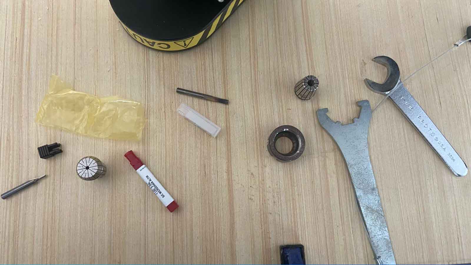
Milling cutter change
To change the tool (milling cutter) in the Shopbot, it is necessary to wear protective gloves and glasses. To do this, first we deactivate the key and carefully turn the collet with the keys indicated, photos of the change and an explanatory video are attached.
Cuts and more cuts
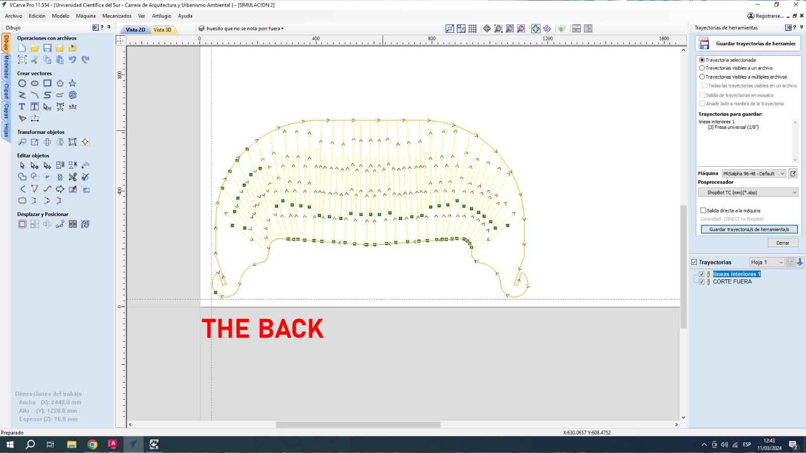
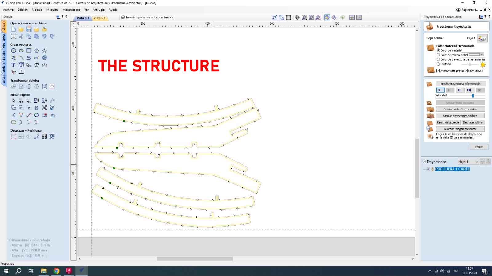
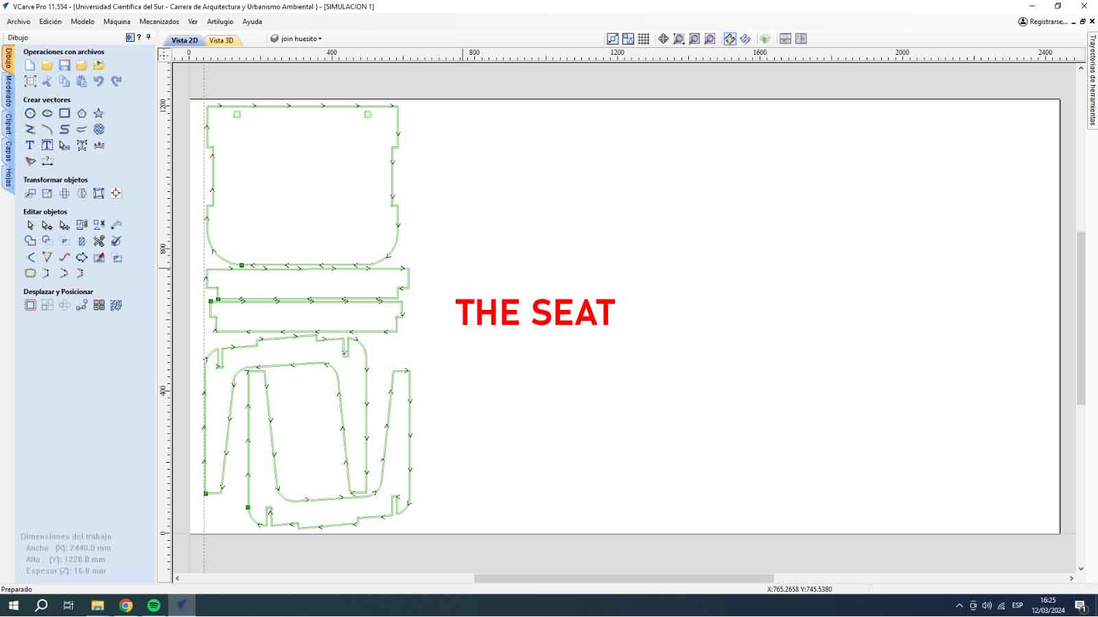
Here are some links to my V-Carve Pro trajectory files, as well as the editable CAD of the project.
Sending by parts the project of the chair, I had 3 tests, I indicate the cutting time:
First Test: Only seat, legs and structure - 25min.
Second Test: Only backing with 1/8" drill - 30min.
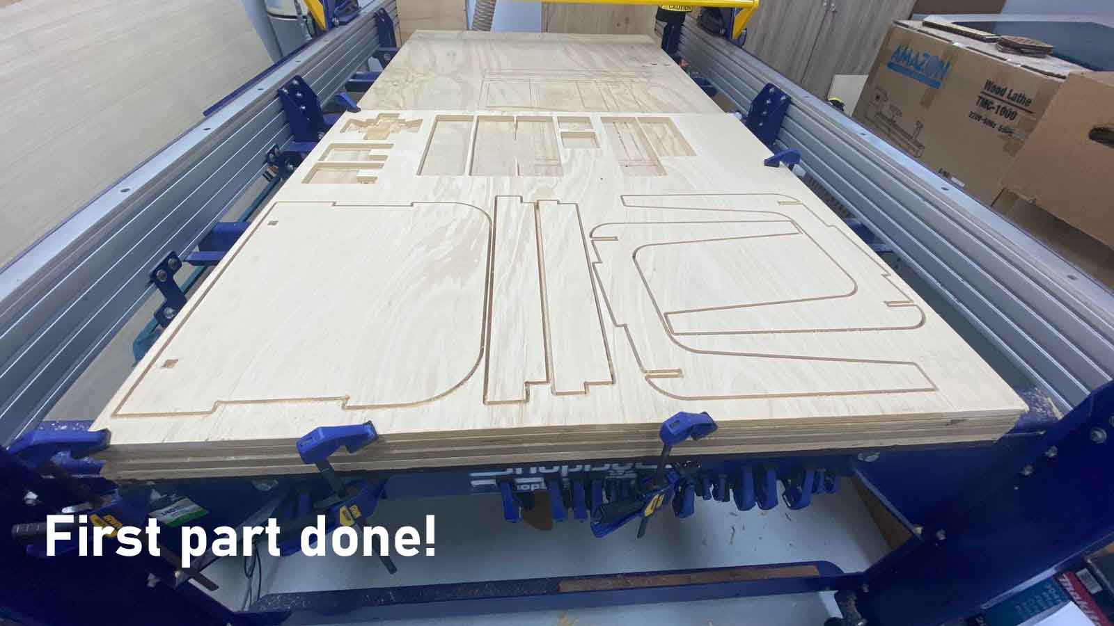
The first part of the cuts was made in a 0.70x0.50m piece that we had left over from a previous cut, the assembly was very fast and we did not take long to fit the pieces, here some pictures of the process.
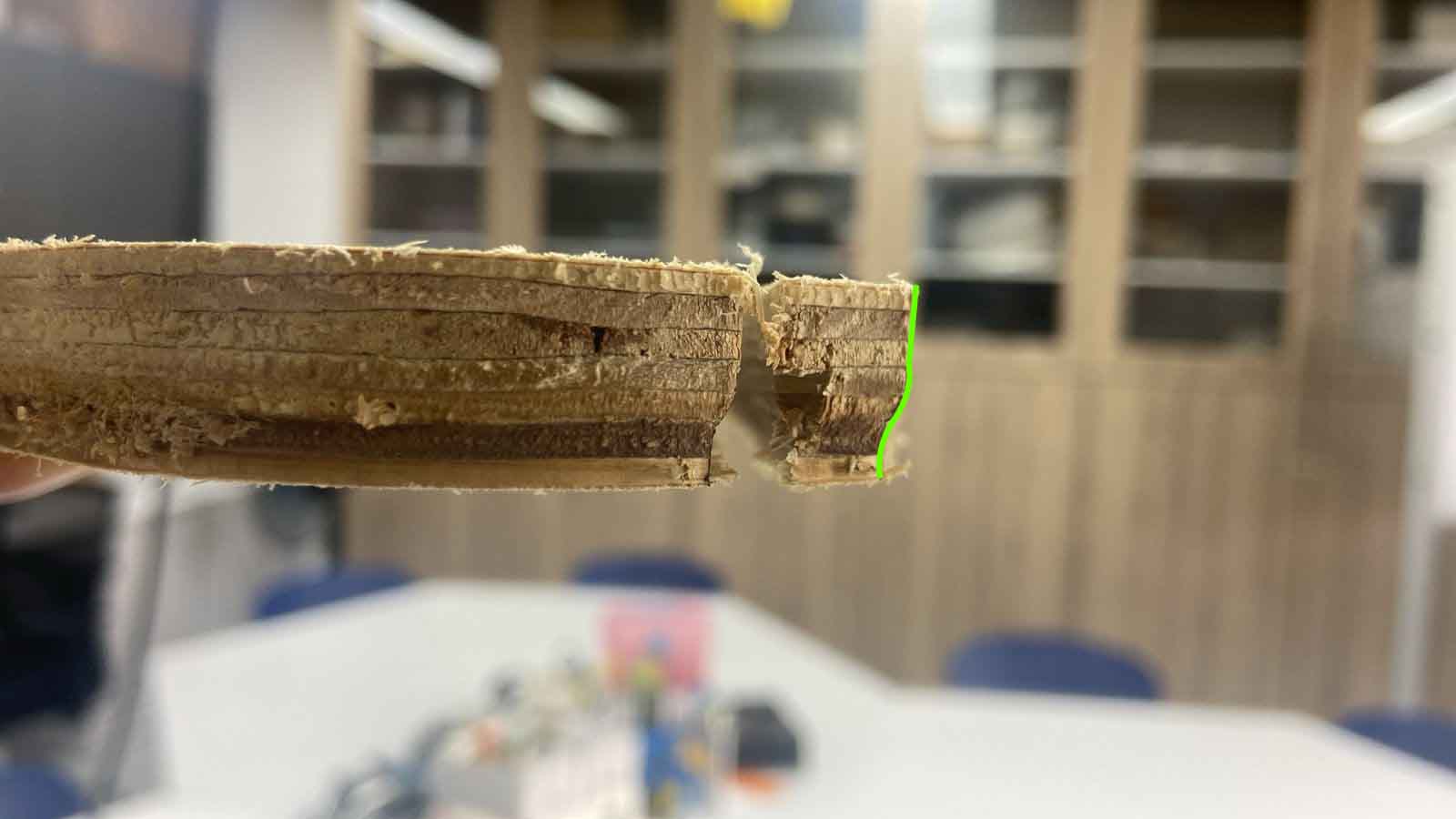
All is well, so we can start with the cutting of the backing! But, it is here where many failures arose, first by the type of drill bit from 3/4 I went to 1/8 for the separation between each cutting line, so that this made the cuts come out very very thin and break much easier, here I leave what happened.
Second attempt, change of drill bit and off we go! from the 1/8 we go to the 3/4 because the 1/8 left the cut with an inner bevel, photo below.
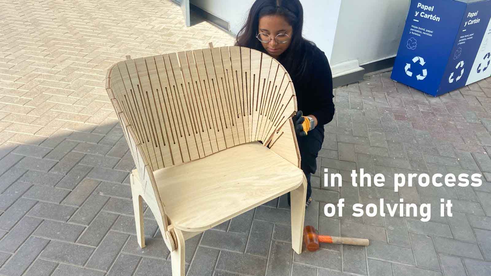
How was this solved?
The flex part was improved by changing the milling cutter from 3/4 to 1/8 so that it left more room on the edges for cutting, the fits were better adjusted and the openings between the flex parts are much closer together.
In addition, by changing the milling cutter, the profile left at the time of cutting was also solved.
Here I re-cut the part with the new milling cutter.
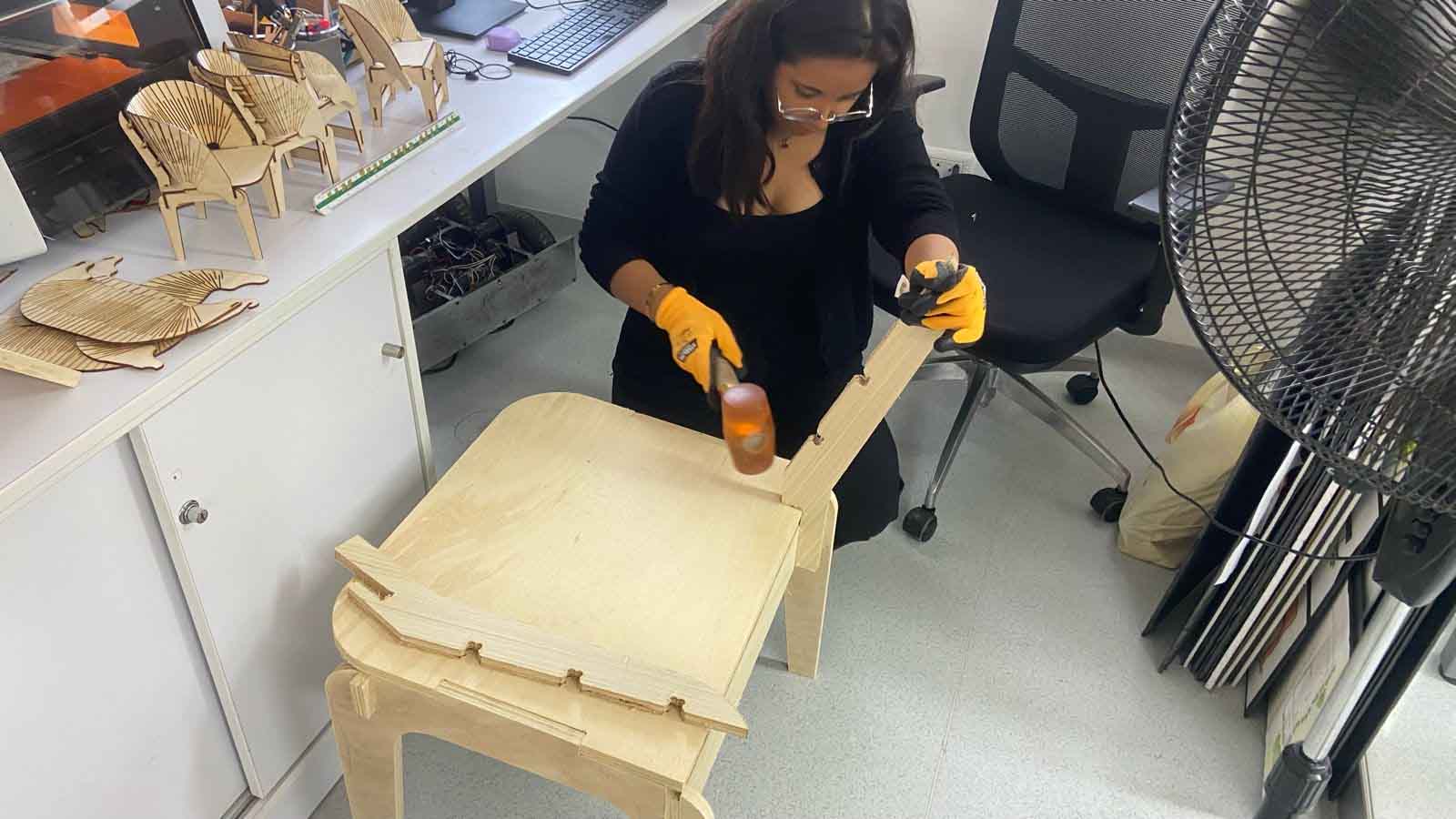
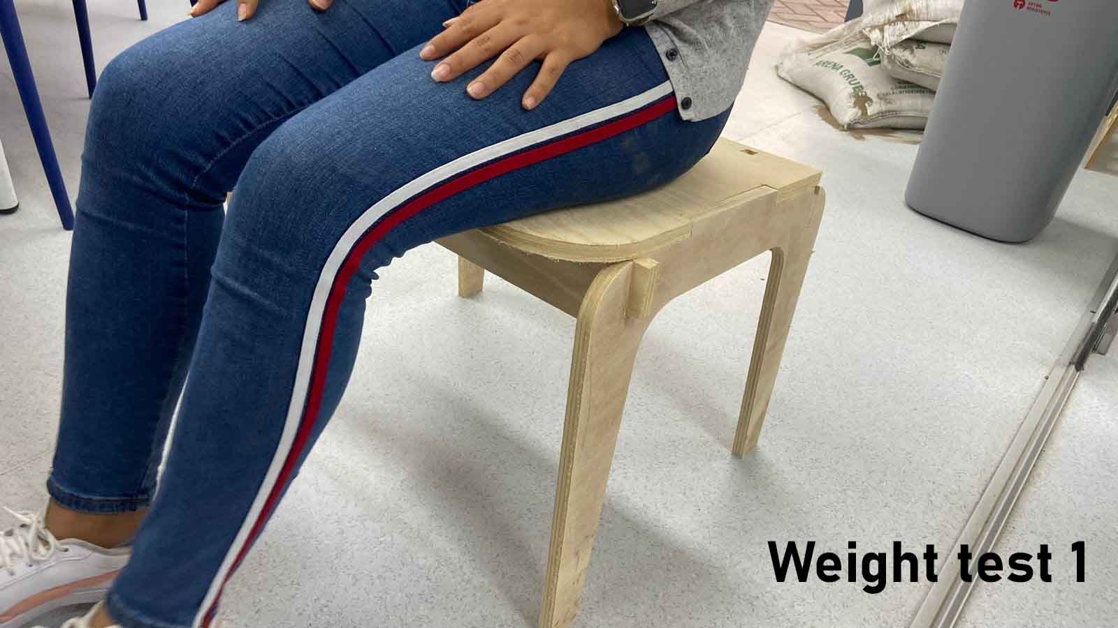
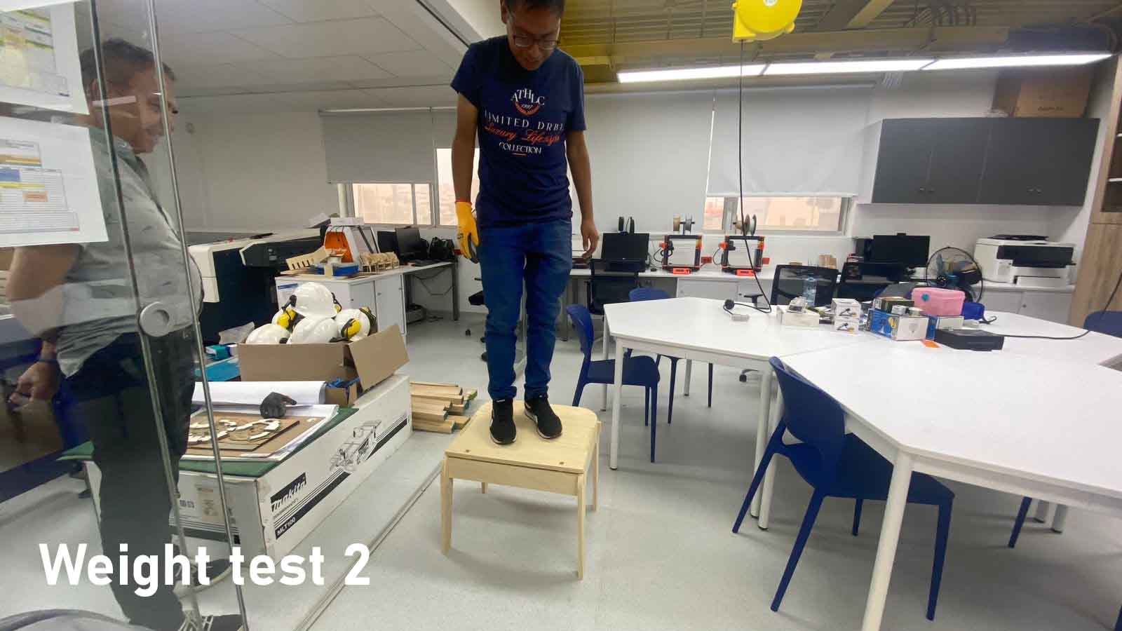
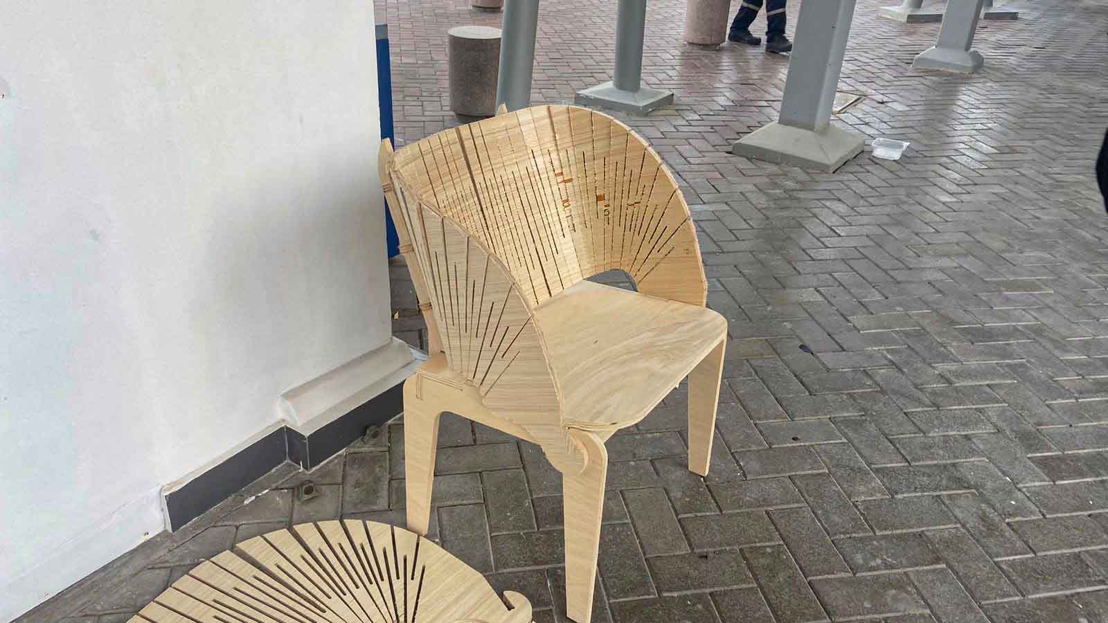
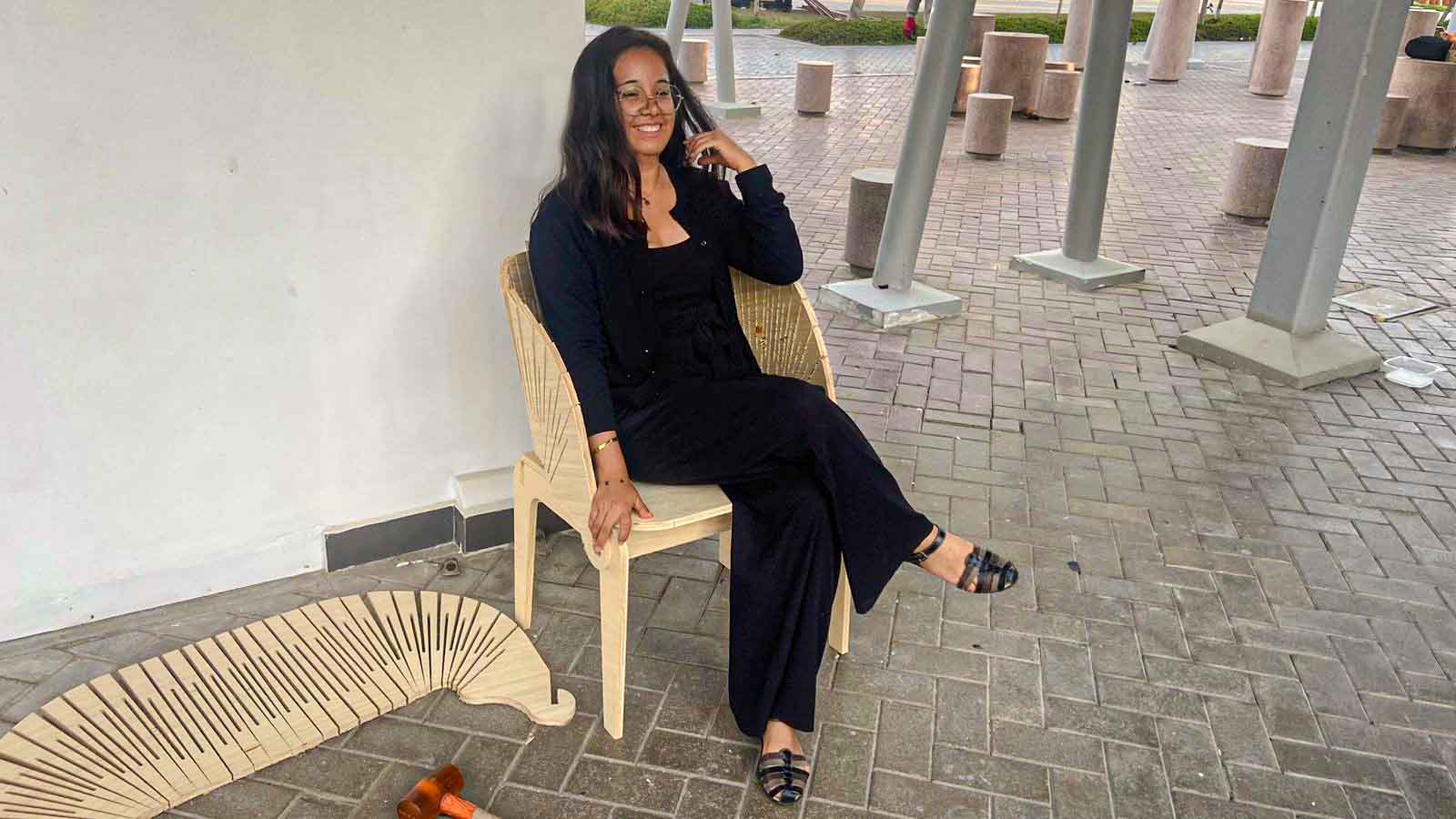
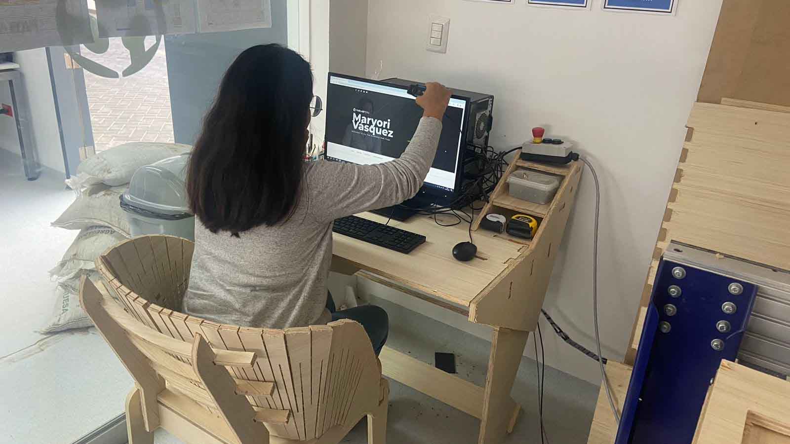
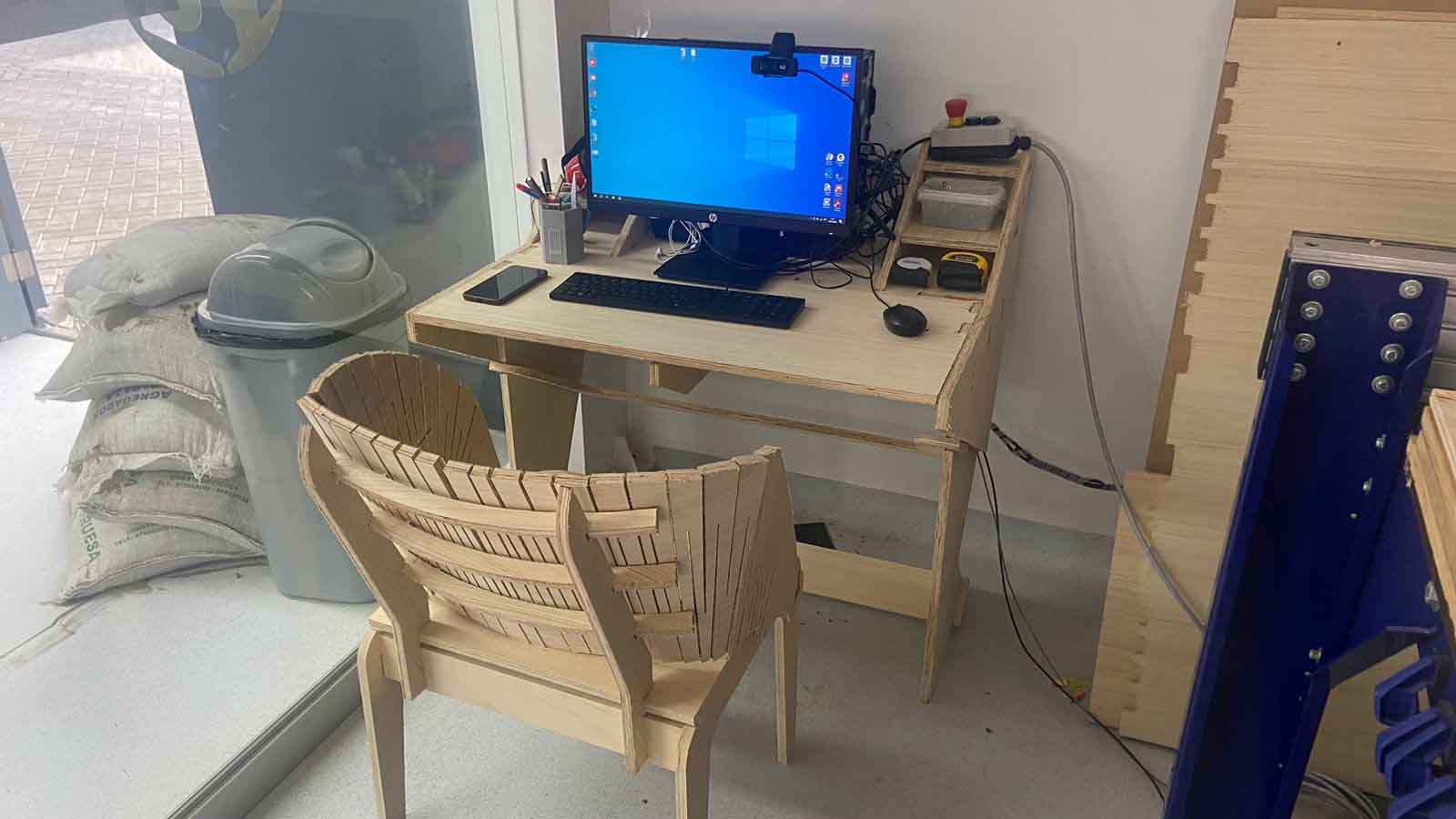
Finaly: Assembly!
This long process helped me to improve my design skills! It was a challenge to finish it and above all to use the CNC, very interesting how I was able to get ahead with little experience but a lot of theory!
Finally I kept the 1/8" milling cutter and with it I made the cut, the chair has a very fine finish and is also quite comfortable! I leave this experience as the most fun of the Academy!
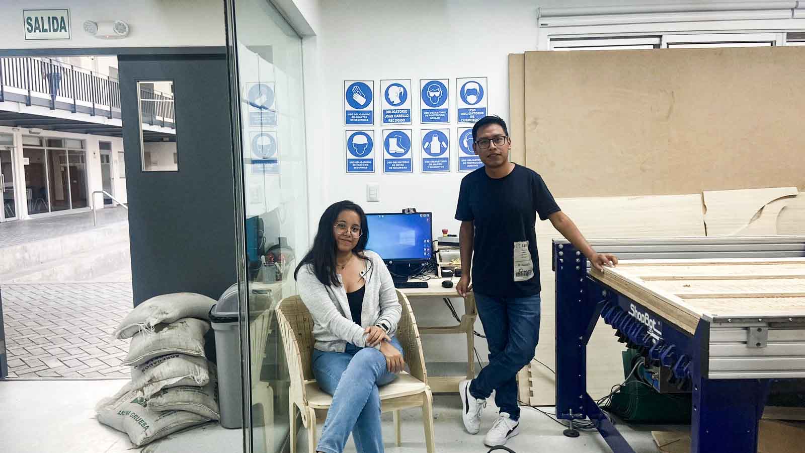
Here's a few photos of my friend Hans and I with our models!
Copyright 2023 Maryori Vásquez- Creative Commons Attribution Non Commercial