Week 6

Embedded Programming

Group Assignment

LINK TO THE GROUP ASSIGNMENT PAGE
We've to do

- See the datasheet of our microcontroller sample

- Compare performance and development workflows of other architectures

Materials

Recognition of materials in the inventory, what can we do with it, what features does it contain that will help us to program it with the Queentorres

Development

Development of the research and various results

First meetings

To carry out the group work, on Thursday, 02/29/2024 we met with our local instructors, to support us in a general way on the programming of our plates, the detail and explanation of the assignment of the week.

LINK TO THE ASSIGNMENT WEEK
Download free bootstrap 4 landing page, free boootstrap 4 templates, Download free bootstrap 4.1 landing page, free boootstrap 4.1.1 templates, meyawo Landing page
SEEED STUDIO XIAO RP2040 MICROCONTROLLER

At the Academy, we have been recommended to use SEEED STUDIO XIAO RP2040, a versatile microcontroller that will help us in the following assignments and also in the final project. Here some Features:

1. Raspberry Pi RP2040 microcontroller: The RP2040 is a dual-core ARM Cortex-M0+ microcontroller running at 133 MHz, with a range of peripherals and exceptional performance for low-power applications.

2. USB-C connectivity: Uses a USB-C port for power and programming, making it easy to connect and program the board to a variety of systems.

3. Arduino compatibility: It is compatible with the Arduino development environment, enabling users with a wide range of available libraries.

4. Small form factor: It has a small form factor, ideal for applications where space is limited, such as wearables, portable devices and sensors.

5. Support for multiple communication interfaces: It has a variety of communication interfaces, including UART, SPI, I2C and USB, making it suitable for a wide range of embedded electronics and IoT applications.

Download free bootstrap 4 landing page, free boootstrap 4 templates, Download free bootstrap 4.1 landing page, free boootstrap 4.1.1 templates, meyawo Landing page
DATA SHEET SEEED STUDIO XIAO RP2040

Supports different programming languages such as C++, MicroPython, Python, Arduino IDE, compatible with the Raspberry Pi RP2040 ecosystem, here are some features:

- Memory: 264 KB RAM and 2 MB QSPI flash memory.

- Connectivity and Compatibility: USB-C for power and programming, with Arduino and CircuitPython development environment

- Communication interfaces: UART, SPI, I2C, USB.

- Form factor: Small, ideal for space-constrained applications.

- Peripherals and Power supply: 30 GPIO pins, 2 status LEDs and 3.3V

- Applications: Ideal for IoT projects, embedded electronics, wearables and portable devices.

Download free bootstrap 4 landing page, free boootstrap 4 templates, Download free bootstrap 4.1 landing page, free boootstrap 4.1.1 templates, meyawo Landing page
SEEED STUDIO XIAO ESP32-C3 MICROCONTROLLER

1. ESP32-C3 microcontroller: A single-core RISC-V microcontroller running at 160 MHz.

2. USB-C connectivity: The XIAO ESP32-C3 board uses a USB-C port for power and programming.

3. Arduino compatibility: Compatible with the Arduino development environment.

4. CircuitPython and MicroPython compatibility: Two popular programming languages for microcontrollers.

5. Bluetooth and Wi-Fi support: Wireless connectivity, allowing you to communicate with other devices via Bluetooth and Wi-Fi.

Download free bootstrap 4 landing page, free boootstrap 4 templates, Download free bootstrap 4.1 landing page, free boootstrap 4.1.1 templates, meyawo Landing page
DATA SHEET SEEED STUDIO XIAO ESP32-C3

- Microcontroller: ESP32-C3, a single-core RISC-V microcontroller running at 160 MHz.

- Memory: 400 KB RAM and 384 KB flash memory, USB-C input for power and programming, and support for Bluetooth and Wi-Fi.

- Compatibility: Arduino, CircuitPython and MicroPython development environments.

- Communication interfaces: UART, SPI, I2C, USB and microSD card support.

- Peripherals: External antenna connector, lithium battery connector and 30 GPIO pins.

- It has 11 digital I/O that can be used as PWM pins and 6 analog I/O that can be used as ADC pins. Supports all three common serial interfaces such as UART, I2C and SPI.

COMPARISON WITH OTHER ARCHITECTURES

Download free bootstrap 4 landing page, free boootstrap 4 templates, Download free bootstrap 4.1 landing page, free boootstrap 4.1.1 templates, meyawo Landing page
ABOUT

All microcontrollers are unique and special, they can be suitable for different types of projects. In the case of the ATTINY412 it is ideal for low-power applications thanks to its wide range of peripherals.

SAMD11

The C is a great choice for projects that require high processing power and a wide range of communication interfaces.

The XIAO RP2040 and XIAO ESP32-C3 are excellent choices for IoT and embedded electronics projects thanks to their wireless connectivity and wide range of peripherals.

Download free bootstrap 4 landing page, free boootstrap 4 templates, Download free bootstrap 4.1 landing page, free boootstrap 4.1.1 templates, meyawo Landing page
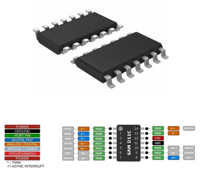
SAMD11C MICROCONTROLLER

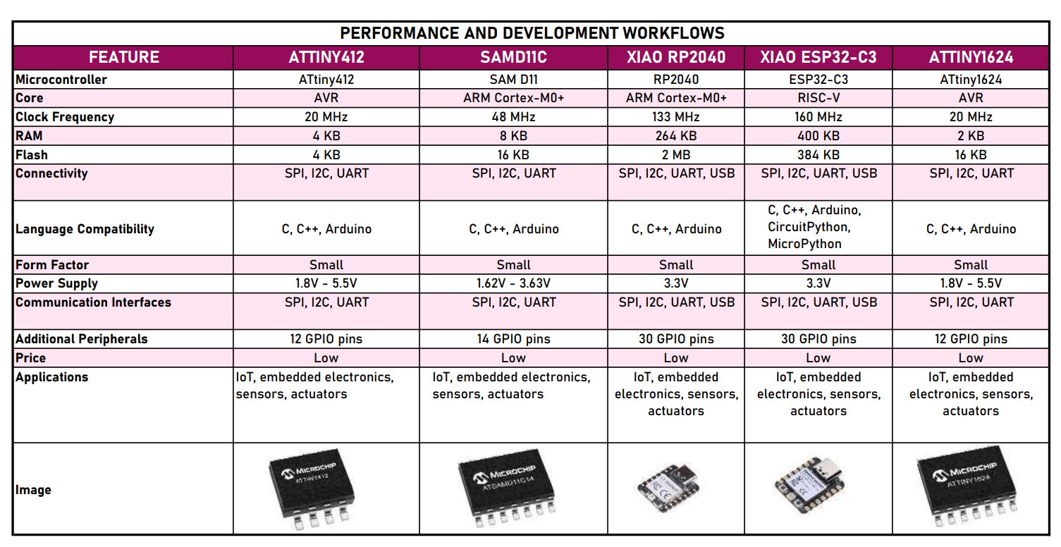
It is part of the SAM D11 family, it offers a balance between performance and energy efficiency. With its 32-bit ARM Cortex-M0+ architecture and speeds up to 48 MHz, it is ideal for a variety of embedded applications. Its numerous connectivity peripherals and GPIO ports make it perfect for embedded systems, wearable devices, and IoT projects that require low power consumption

1. ARM Cortex-M0+ architecture: Offers a balance between performance and energy efficiency, suitable for low-power applications.

2. Speed up to 48 MHz: Allows fast data processing and operations.

3. Connectivity peripherals: Includes USB, UART, SPI and I2C to facilitate communication with other devices.

4. GPIO Ports: Provides flexibility for interfacing with sensors, actuators and other external devices.

5. Low power consumption: Ideal for applications that require long battery life, such as wearable devices and IoT systems.

6. Wide variety of applications: Suitable for embedded systems, wearable devices, device controllers and IoT projects.

MORE CONCLUSIONS

The ATTINY1624 is ideal for low-budget projects due to its low cost and wide range of peripherals. In general, the choice of the right microcontroller will depend on the specific needs of your project, such as performance, connectivity, power consumption and cost.

We did the microcontroller comparison virtually where we met until very late, but we learned a lot about their differences, learned to know more programming and electronics terms. Finally, here is a picture of us when we finished the group work, all very tired but with strength to continue with FAB ACADEMY.

LINK TO THE PDF FILE

Individual Assignment

LED PROGRAMMING

LED programming is done through the Blink from the Arduino.

MOTION SENSOR

With the motion sensor in our inventory, we will try to connect the XIAIO to achieve its operation.

DISTANCE SENSOR

The distance sensor is connected to the board to determine its operation.

Download free bootstrap 4 landing page, free boootstrap 4 templates, Download free bootstrap 4.1 landing page, free boootstrap 4.1.1 templates, meyawo Landing page
Installation and configuration ARDUINO.IDE

To start programming our QUENTORRES board, I use the ARDUINO.IDE, from here I start with the programming for the LED's on through the button.

ARDUINO.IDE SOFTWARE

Follow the steps in the img

Being in the program we go to FILES/PREFERENCES , here 2 links are added so that the program can download all the relevant information about the XIAO RP2040. Here I leave the 2 links to copy and paste in the ADDITIONAL TABS section. Finally we click OK and it will start downloading all the necessary information.

PACKAGE PRO RP2040 PACKAGE ESP32
Next Step

Next click on TOOLS / TABLET / TABLET MANAGER , in the tab put the word PICO and install the document called RASPBERRY PI PICO / RP2040.

Finally, we look under TOOLS/TARJETA/RASPBERRY PI PICO/RP2040 and add the SEEED XIAO RP2040 processor. This confirms that the installation is correct and we can start programming.

DOWNLOAD THE URL'S HERE
                            
                
                // define led acording to pin program
                int led = 26;
                void setup() {
                // initialize digital pin led as an output
                pinMode(led, OUTPUT);    
                }


                void loop() {
                digitalWrite(led, HIGH); // turn the LED on
                delay(1000); // wait for a second
                digitalWrite(led, LOW); // turn the LED off
                delay(1000); // wait for a second


                }
                
            
Blink!

I USED THIS CODE FROM THE COMMON PROCESSES OF THE ARDUINO, IT COMES BY DEFAULT IN THE PROGRAM.

- I want to BLINK the first LED connected to PIN 26 or D0, so that it only blinks without activation without a pushbutton.

- The programming is divided in 3: DEFINITION, VOID SETUP and VOID LOOP. In the first one you define the PIN, in VOID SETUP, the LED as output and in VOID LOOP, the time and the flashing that the LED will have.

- After programming it, click on VERIFY at the top left and after that, click on UPLOAD where we load the code to the board and automatically you will see the process in action!

BLINK FILE .INO

        const int ledPin1 = 26;//first light  RP2040 pin 0
        const int buttonPin = 27;// button pin  RP2040 pin 1 
        int buttonState = 0;//initial state of the button
        int i = 0; //variable intensity led
                
        void setup() { //declaration of inputs and outputs
            pinMode(ledPin1, OUTPUT);
            pinMode(buttonPin, INPUT);
        }
        void loop() {
        buttonState = digitalRead(buttonPin);// we read the 
        state of the button if (buttonState == HIGH) { //if we press the button
        digitalWrite(ledPin1, HIGH);
        delay(500);                       
        digitalWrite(ledPin1, LOW);    
        delay(500);
        digitalWrite(ledPin1, HIGH);
        delay(500);                       
        digitalWrite(ledPin1, LOW);    
        delay(500);
        digitalWrite(ledPin1, HIGH);
        delay(2000);                        
        digitalWrite(ledPin1, LOW);    
        delay(1000);
                  
        }
        else {  //if we don't press the button
        digitalWrite(ledPin1, LOW);
        }
        }
                
            
Input Button

THE CODE I GOT IT FROM ADRIAN'S SITE

ADRIAN TORRES PAGE

With the following code you can make the push button programmed with the LED, code is attached.

PRESS BUTTON .INO

                // Define the pins to be used
                const int trigPin = 2; // Output pin of the ultrasonic sensor
                const int echoPin = 3; // Input pin of the ultrasonic sensor
                
                // Define variables to store the times
                long duration;
                int distance;
                
                void setup() {
                  // Initialize the pins as input or output
                  pinMode(trigPin, OUTPUT);
                  pinMode(echoPin, INPUT);
                
                  // Initialize serial communication
                  Serial.begin(9600);
                }
                
                void loop() {
                  // Send a 10-microsecond pulse to the output pin
                  digitalWrite(trigPin, LOW);
                  delayMicroseconds(2);
                  digitalWrite(trigPin, HIGH);
                  delayMicroseconds(10);
                  digitalWrite(trigPin, LOW);
                
                  // Measure the time it takes for the echo to arrive
                  duration = pulseIn(echoPin, HIGH);
                
                  // Calculate the distance in centimeters
                  distance = duration * 0.034 / 2;
                
                  // Print the distance to the serial console
                  Serial.print("Distance: ");
                  Serial.print(distance);
                  Serial.println(" cm");
                
                  // Wait a moment before repeating
                  delay(1000);
                }
                
            
Distance Sensor

Here I could help me with Adrian's Page to make the connection of the Quentorres with the sensor, in this way through the DATASHEET and Dupont Jump female/female cable.

ADRIAN TORRES PAGE SENSOR DISTANCE .INO

           #define SENSOR_PIN 2  // Cambia este número al pin 
           al que hayas conectado la salida del sensor

           void setup() {
           Serial.begin(9600);
           pinMode(SENSOR_PIN, INPUT);
            }
                
           void loop() {
           int motionDetected = digitalRead(SENSOR_PIN);
                
           if (motionDetected == HIGH) {
           Serial.println("Movimiento detectado");
           } else {
           Serial.println("Sin movimiento");
           }
                
          delay(1000);  // Puedes ajustar el tiempo de espera 
          según tus necesidades
          }


Movement Sensor

I got help from Adrian Torres but I also made some modifications in the code, to understand it better I asked Chat GPT for help.

ADRIAN TORRES PAGE

- Here is the Prompt:

"Hello! Chat GPT give me the code in ARDUINO.IDE to program a RCWL-0516 Motion Direction Distance 5-7m and tell me in which pins I have to connect in the XIAO RP2040."

- Then I question about the pins, here is the prompt:

"Which pins do I connect the sensor to ground, power supply and Out"

- Then I checked the Xiaos's DATA SHEET and the sensor's pins, below this page you can check the steps

SENSOR MOVEMENT .INO