About the scanner
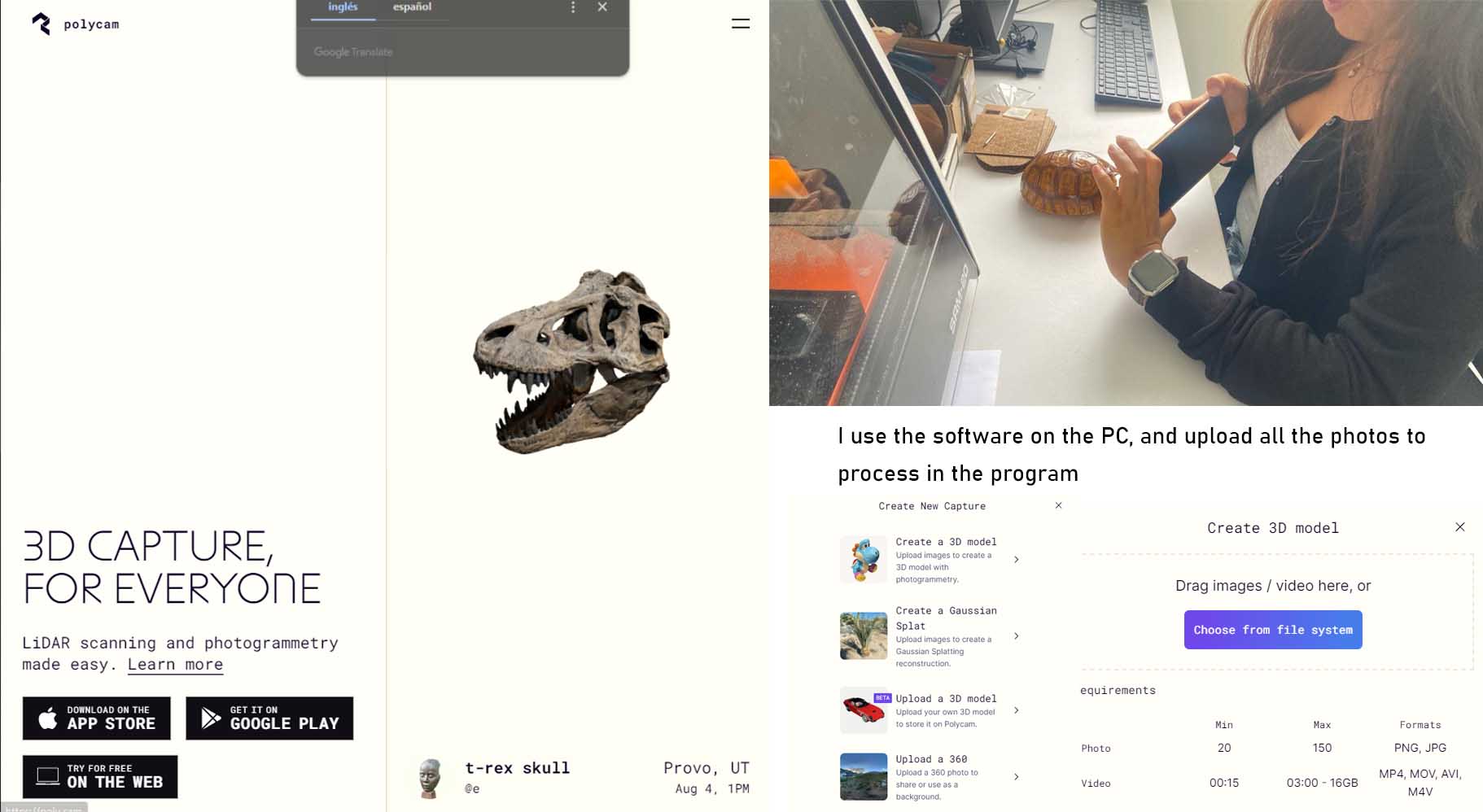
I chose this 3D scanner, by recommendation, the result is much better than other applications that I had tried in the past, here I explain the steps, first I started by downloading the application, I leave the link here
LINK TO THE POLYCAM SOFTWARE
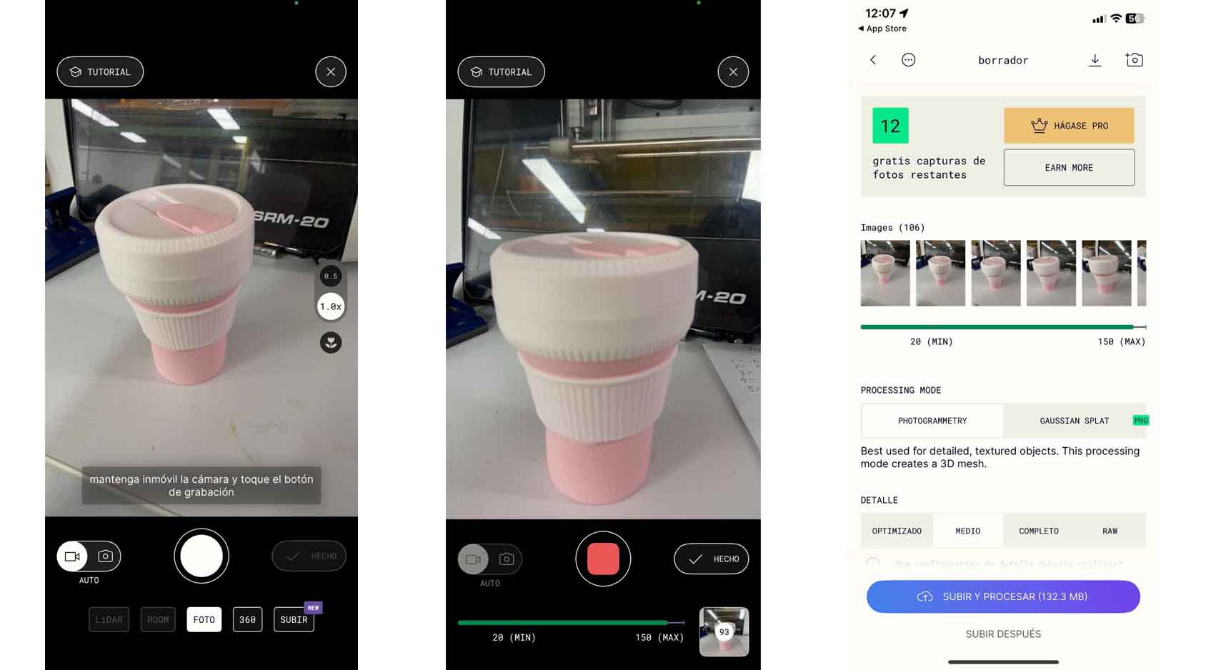
From here we can select the object, better if it is on a flat surface and there are few things around it, so that we can focus on only that element, from the sgt image we can verify the first capture through video, the software allows 150 photos.
After that we can press the red button for the capture, automatically when we press DONE, it will send us to the processing, here I waited approx. 5 minutes.
After loading the processing, the whole model came out, from here we can see that it is inside the purple box, what I did was to cut it more detailed to finally download it in a GLTF file, I can open it in any modelling program to start configuring it.
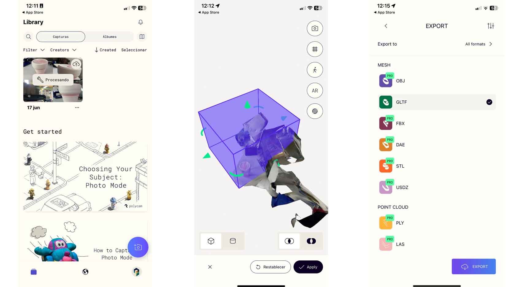
Here is a video of the object in AR to show the level of detail of the scan.