Week 4

Electronic Production
LINK TO THE GROUP ASSIGNMENT PAGE

Group Assignment

Characterizing material and machinery

Design rules, material identification, theory and practice with milling machinery.

In-house board production process

First designs, testing of speed, power, depth of cut and milling, pre-visualization of results, depths.s

Testing and circuitry

First soldering tests, multimeter verification, applications and improvements.

Download free bootstrap 4 landing page, free boootstrap 4 templates, Download free bootstrap 4.1 landing page, free boootstrap 4.1.1 templates, meyawo Landing page
Inventory

Before starting the tasks, together with my partner Hans, we made a complete inventory of all the electronic components and tools we needed for this assignment, as well as an inventory of the things we were missing.

We were able to verify that we have 1/64 and 1/32 milling cutters!

Here we have all the parts to use and assemble! Let's get to work!

Download free bootstrap 4 landing page, free boootstrap 4 templates, Download free bootstrap 4.1 landing page, free boootstrap 4.1.1 templates, meyawo Landing page
Milling Machine

The milling machine that we have at the Universidad Cientifica del Sur is the MONOFAB SRM-20 that we will use for this week's assignment. Here are some specifications of the machine:

Read more about the SRM-20

WORK SURFACE 232.2 x 156.6 mmm
OPERATING SPEED 6 mm/min to 1.800 mm/min
POWER CONSUMPTION 50 W
SPINDLE ROTATION SPEED 3.000 RPM to 7.000 RPM
Download free bootstrap 4 landing page, free boootstrap 4 templates, Download free bootstrap 4.1 landing page, free boootstrap 4.1.1 templates, meyawo Landing page
Step 1

TRACE WIDTH TEST

We start with the preparation of the cutting area, we place the double contact tape on a small ABS base (we chose it for the height and density) in order to avoid damaging the base of the milling machine.

Then we put the copper plate secured with the same tape, so that it does not move, preventing the milling cutter from breaking.

Download free bootstrap 4 landing page, free boootstrap 4 templates, Download free bootstrap 4.1 landing page, free boootstrap 4.1.1 templates, meyawo Landing page
Step 2

CALIBRATION

After having the circuit board correctly glued. We configure the X, Y and Z axes of the milling machine. We start with X and Y, aligning where we want to start the work, with the help of a bond sheet we calibrate the Z axis. We will be careful and work with the movement in x10 or x100 depending on the case.

After obtaining the correct location of the X, Y and Z axes, we set the origin from the program. This is where all the values will change to 0.00 mm and the machine will be ready to start working.

Step 3

LINE TEST

Descripción de la imagen

- We will start with the line test, where we will perform the milling in the following image, remember that first we will perform the milling and then the cutting. For this first step we have to download the figure and pass it to the IMODELA CREATOR program , which is the program we use before moving to the machine program.

- We first import the TRACES to IMODELA CREATOR to start milling and configuring the machine, remember that we will use the 1/64 drill bit for this occasion.

- The IMODELA CREATOR program has the ability to show us a simulation of how the work we previously did would turn out. We thought it was good, so we sent it to be cut but the result was not what we expected.

- After importing, we proceed to cutting with the machine. In the first test we failed because the cut came out the other way around, that is, instead of cutting the part that we didn't need (black area), it started cutting the lines and numbers (white area) and this is the result. But the cut was precise and showed very well.

RESULTS

After the import, we proceed to the cutting with the machine. In the first test we failed because the cut came out backwards, that is, instead of cutting the part we did not need (black area), it started to cut the lines and numbers (white area) and this is the result. But the cut was accurate and looked very good.

Descripción de la imagen Descripción de la imagen Descripción de la imagen
Tests

A FEW ERORRS

Descripción de la imagen

From here we had 5 more failures due to the frustration we had, we couldn't understand that we were wrong. Here is a photograph of the errors we had.

Descripción de la imagen

1. First test: Problems in the gluing of the copper plate as a base in the milling machine. The cut started to move and came out of the base, interrupting the movement and causing a bad test.

2. Second test: Problems in the inversion of layers, we milled the inverse of what we wanted to achieve, so the test came out wrong, problems in the layer configuration in the Cut studio.

3. Third test: Configuring the modifications in the engrave and pocket, it was still not possible to clean the surplus and the result was the inverse.

4. Fourth test: We did it! the cut values were modified to obtain the inverse, it should be noted that we have better control by changing the color of the layers.

Descripción de la imagen Descripción de la imagen Descripción de la imagen

A long

reunion

Many tests and great lessons learned

Individual Assignment

Setup and Milling

Re-configuration of machinery and parameters.

More Setup

More configurations to ensure results, verification and pre-milling simulation.

First Results

First cutting and milling results, channel verification

Download free bootstrap 4 landing page, free boootstrap 4 templates, Download free bootstrap 4.1 landing page, free boootstrap 4.1.1 templates, meyawo Landing page
Drills, Interiors and Traces.

Through the PNG of the plate in 3 layers: DRILLS, INTERIOR and TRACES, we import to the iModela program, we consider:

- After importing we can VECTORIZE the PNG to find the strokes to make, we must select "EXTRACT CONTOUR LINES", in preview we verify it, click on "OK".

- It is important to set the thickness of the plate and the thickness of what we are going to mill, to avoid the milling being too deep

- We will configure the cutting speed, thickness and passes, it is determined in the following image.

Download free bootstrap 4 landing page, free boootstrap 4 templates, Download free bootstrap 4.1 landing page, free boootstrap 4.1.1 templates, meyawo Landing page
More Settings

- The diameter of the milling must be changed according to the 1/64" - 0.39 mm milling cutter in order to obtain good detail on the plate.

- In the “MILLING PARAMETERS” button I configure the cutting speed, the number of passes and save for safety.

- Then we simulate the milling with the "3D Preview" button, checking that the traces are correct.

- We activate "OUTPUT TO FILE" to create a .pcm file, save and open the Monofab Panel to load from "Cut" using the Add button, the .pcm file, this is the final step to send to milling.

Queentorres website to understand
Download free bootstrap 4 landing page, free boootstrap 4 templates, Download free bootstrap 4.1 landing page, free boootstrap 4.1.1 templates, meyawo Landing page
First Result

This is the result of the milling and cutting of the plate, everything is fine except for the OFFSET of the FOOTPRINTS, which should be wider, however in our meeting on Saturday 02/17/2024 we did not resolve it.

I couldn't find a way to enlarge the milling with the 1/64" milling cutter, so we used the 1/32" milling cutter, however, on the very close TRACES they were tight.

Download my files
Switching programs
Descripción de la imagen

I was thinking that maybe the error came from the iModela program, so I had to change to MODS, from here I show you the steps to download the file, I leave it in the link.

The first test with this MODS was a total success!

Descripción de la imagen

About the values, these are the most important:

Milling Traces

CUT DEPTH: 0.004 in

SPEED: 4mm/s

Milling Parameters

CUT WIDTH: 0.4mm

CUT DEPTH: 1.134mm

Mill Raster 2D

OFFSET STEPOVER:0.5

With these modifications we can ensure that our model to be milled is correct and with the necessary depths.

MODS WEB SITE Download my files
Download free bootstrap 4 landing page, free boootstrap 4 templates, Download free bootstrap 4.1 landing page, free boootstrap 4.1.1 templates, meyawo Landing page
Two Test

I was able to perform two tests with different depths, I verified that some of the circuits were very thin, so I performed the second test, highlighting the paths with greater depth.

The first test was milled in 25 minutes, the cut in 5 minutes.

The second test was milled in 35 minutes, the cut in 5 minutes.

Download free bootstrap 4 landing page, free boootstrap 4 templates, Download free bootstrap 4.1 landing page, free boootstrap 4.1.1 templates, meyawo Landing page
Assembling the components

After determining the board to be used, test 2 is chosen, because the channels are shallower and contain more continuity, which serves as a basis for placing our circuits.

Continuing with the selection, we proceed to locate the components in the list:

-SEEED STUDIO XIAO RP2040

-CONN HEADER SMD 10POS 1.27MM

-CONN HEADER SMD R/A 6POS 2.54MM

-Tactile Switch SPST-NO Top Actuated -Surface Mount

-LED BLUE CLEAR 1206 SMD

-RES 1K OHM 1% 1/4W 1206

-RES 499 OHM 1% 1/4W 1206

-CONN HDR 7POS 0.1 TIN SMD* -CONN HDR 7POS 0.1 TIN SMD* -CONN HDR 7POS 0.1 TIN SMD

Descripción de la imagen

Descripción de la imagen

Descripción de la imagen
Download free bootstrap 4 landing page, free boootstrap 4 templates, Download free bootstrap 4.1 landing page, free boootstrap 4.1.1 templates, meyawo Landing page
Soldering!

We performed some welding tests on poorly milled plates, considering the following materials in our space:

- Flux

- Soldering iron

- Tweezers

- Soldering mat

- Magnifying glass

- Base to hold plate

- Tin

We start by placing a little flux, followed by the electronic part, we pass the tin through the tip of the soldering iron until it is tinned, we clean it and take two balls of tin to position directly on the board.

Download free bootstrap 4 landing page, free boootstrap 4 templates, Download free bootstrap 4.1 landing page, free boootstrap 4.1.1 templates, meyawo Landing page
Some comparisons and led testing

I could notice, together with the plate of my partner Silvana, that the routes of my plate are more detailed, this is because the first time we did the test, it was not so good, the routes were very thin so the soldering was even more complex.

You can also see in the images and video that the soldering on the test board 2 is more detailed, allowing the components to adhere more quickly.

Download free bootstrap 4 landing page, free boootstrap 4 templates, Download free bootstrap 4.1 landing page, free boootstrap 4.1.1 templates, meyawo Landing page
Debugging

To debug my board, I used the multimeter and performed continuity tests on the circuits, this in turn complemented with a close-up magnifying glass to get a closer look at the details of my board and corroborate the soldering and, failing that, the solution to achieve continuity and avoid a short circuit.

Descripción de la imagen
Programming

First of all we install the ARDUINO IDE, from this LINK , from here we will have to install some libraries to program the XIAO rp2040, here are the steps:

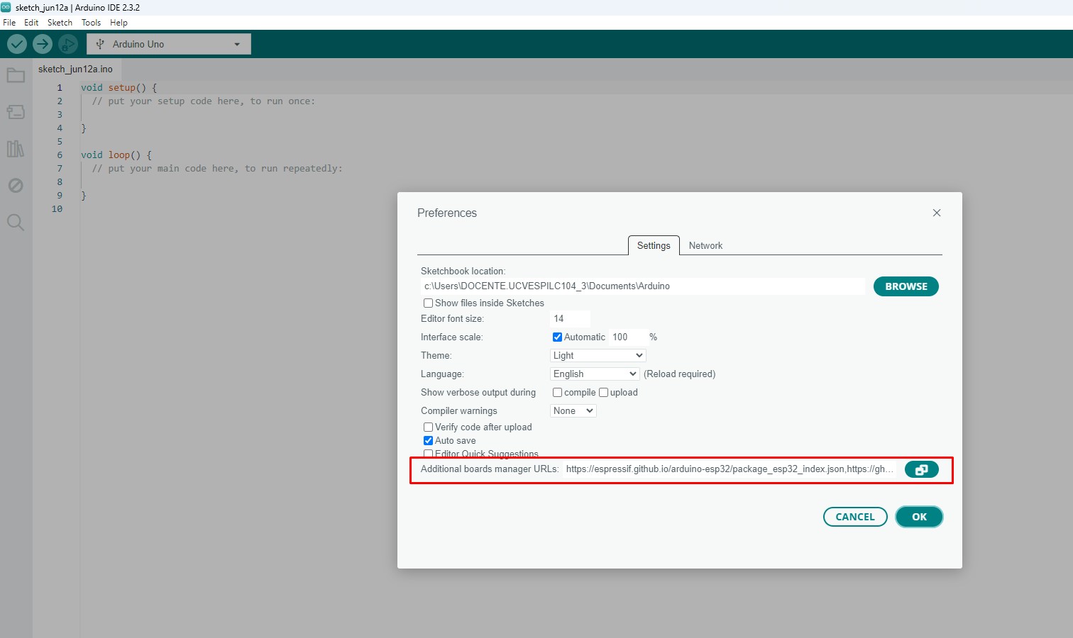
1. From the File button, preferences, we will add 2 links to make the program can start downloading everything that the Xiao needs to work:

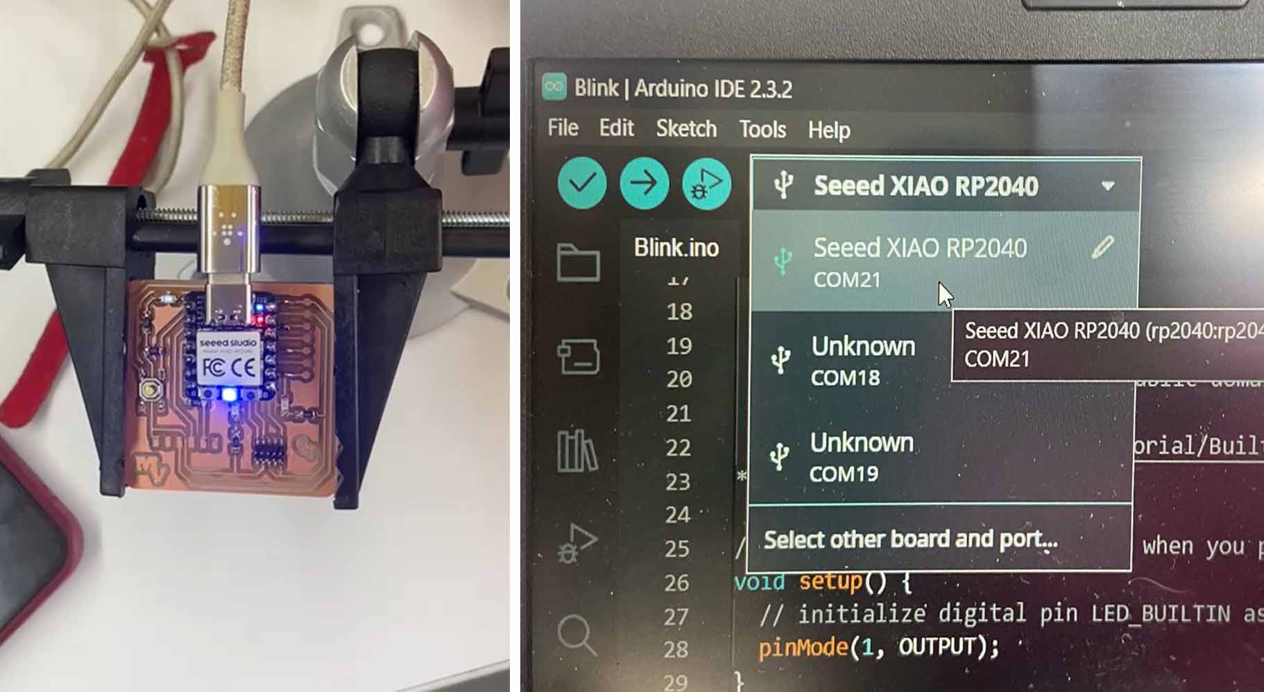
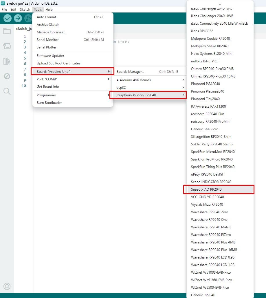
2.Then we go to Tools, Board/ Board Manager and from here we select PICO, until we find RASPBERRY PI PICO / RP2040, finally we select the processor SEED XIAO RP2040, to confirm the installation and start programming.

Descripción de la imagen

Descripción de la imagen

Blink a LED

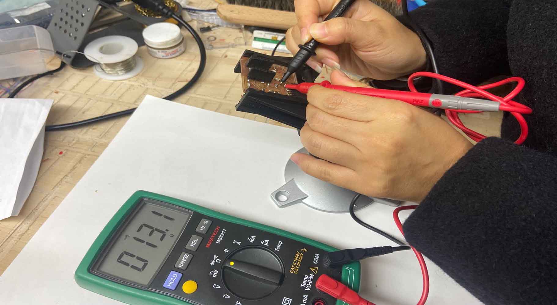
The LED is connected to PIN 26 or D0. Without activating anything, just program a simple blink and see if it works.

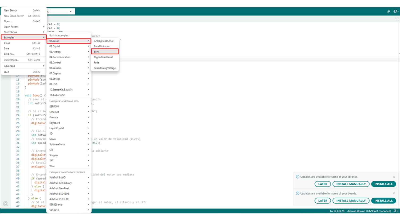
To make the BLINK, we start with an example from ARDUINO IDE. To do this, go to FILES/EXAMPLES/01.BASICS/BLINK.

Here a tab of the ARDUINO IDE will open with the name BLINK.

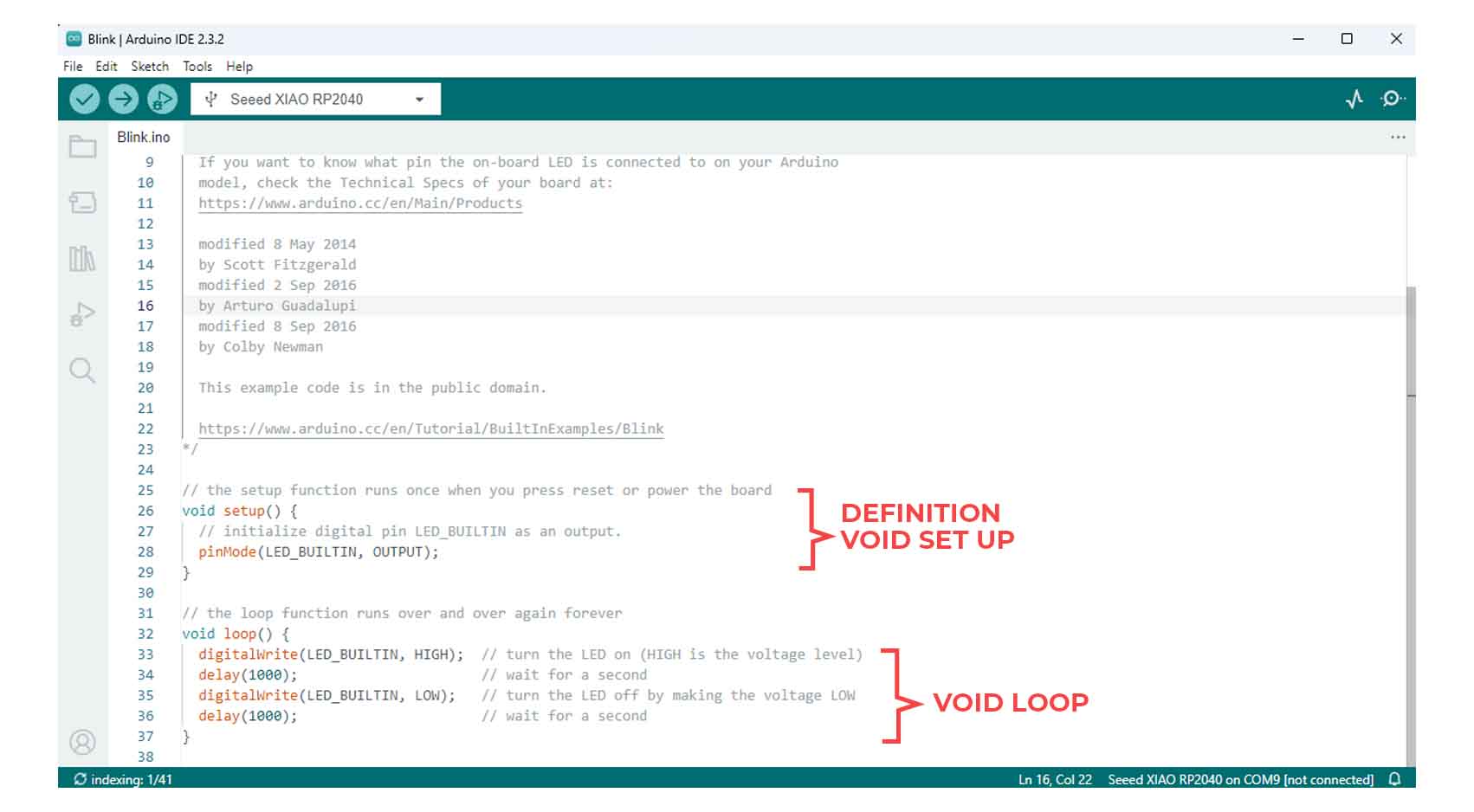
To begin with the code it comprises 3 parts, Definition, VOID Set Up and Loop, from the beginning we indicate the name of the pin that belongs, from the VOID SETUP the LED is configured as information output and from the VOID LOOP the time and its continuous blinking.

After verifying that it is OK, we click on UPLOAD to load it to the QUENTORRES, from here we can see that the LED on pin 26 or D0 does FLAW according to the data mentioned in the program.

Descripción de la imagen Descripción de la imagen
Download free bootstrap 4 landing page, free boootstrap 4 templates, Download free bootstrap 4.1 landing page, free boootstrap 4.1.1 templates, meyawo Landing page
It turns on!

After soldering, the next step is to connect the board with the Xiao to the pc, so that it can be turned on, of course I previously verified that there is no contact between the soldering and the boards, this is how it was finally.