Embedded Programming

This week we will learn about our microcontroller datasheet, compare performance and development workflows for other architectures, and write a program for a microcontroller development board to interact (with local input and/or output devices) and communicate (with remote wired or wireless devices).

the assignment was:

Group assignment: Browse through the data sheet for your microcontroller, compare the performance and development workflows for others architectures

Individual assigment: write a program for a microcontroller development board that you made, to interact (with local input &/or output devices) and communicate (with remote wired or wireless devices).

Extra credit: use different languages &/or development environments, Extra credit: connect external components to the board

Group assignment

We were able to review information on 5 microcontrollers and make a comparison of their performance and general characteristics.

What did I learn?...that there is a wide variety of microcontrollers and that depending on what we want it to do, one of them will work for us. Many of the microcontrollers do not arrive easily to Peru and it takes time to import them.

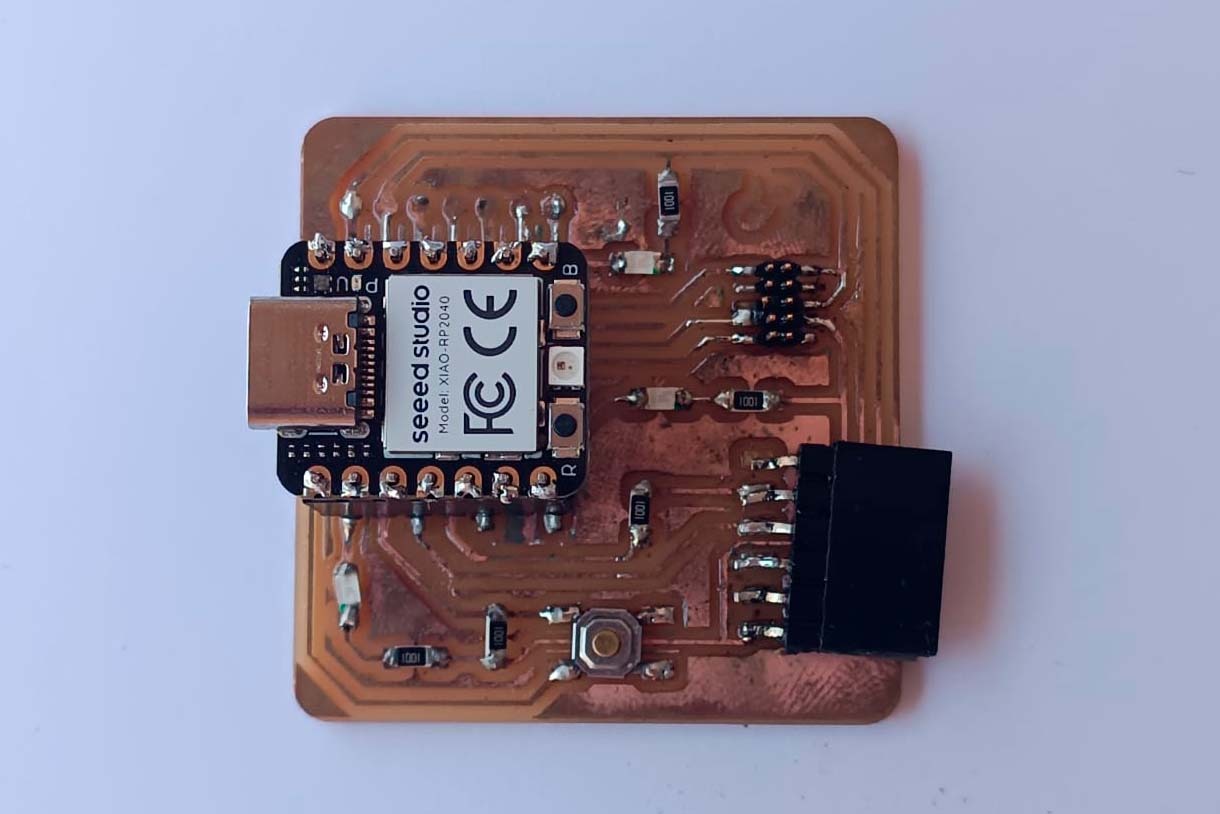
The best microcontrollers that we analyzed due to their performance were the Xiao RP2040 and ESP32-C3

You can see the documentation on the group's web page

Individual assignment

Before writing my first codes

In the assignment 4 electronics production we manufacture the QUENTORRES board.

It was a task that took me several days trying to solder the components to the board, it took me a while because it was the first time I did this kind of task.

The result was satisfactory because it cost me a lot.

What did i learn?...to solder and to have a lot of patience...

As a first step we download and install the latest version of Arduino IDE according to your operating system, in my case Windows

Download link

As a second step we add the XIAO RP2040 board package to the Arduino IDE.

Open the Arduino IDE.

Navigate to File -> Preferences -> and fill Additional boards manager URLs:

Copy and paste this url: https://github.com/earlephilhower/arduino-pico/releases/download/global/package_rp2040_index.json

click OK

As a third step navigate to Tools -> Boards manager...

Type the keywords "RP2040" in the searching blank

Select the lastest version of "Rasberry Pi Pico/RP2040" and install it

Select your board and port

click OK

...Now we are ready and on fire to write our first code...

Planning the assignment tasks first part

The requirement for the first part of the individual assignment is the interaction of input and output with local devices.

The idea for the first part is that each led light can be turned on 5 times by pressing the button.

The led lights 1, 2 and 3 will turn on with a delay of 1000 ms.

Each led light will turn on 5 times

We created a basic workflow diagram in order to better understand the process...

Writing my first lines of code

In the first part of the code we setup the variables

in the second part of the code void setup () we make the settings by defining the input and output pins.

In the third part of the code "Void Loop()" we indicate that it will be executed cyclically (hence the term loop).

      const int ledPin = D0;      // the number of the LED pin
      const int ledPin1 =  D6;    // the number of the LED pin
      const int ledPin2 =  D7;    // the number of the LED pin
      const int buttonPin = D1;   // the number of the pushbutton pin 
      int buttonState = 0;        // variable for reading the pushbutton status
      
      void setup()
      {
        pinMode(buttonPin, INPUT);  // Set buttonPin as an input
        pinMode(ledPin, OUTPUT);    // Set ledPin as an output
        pinMode(ledPin1, OUTPUT);   // Set ledPin1 as an output
        pinMode(ledPin2, OUTPUT);   // Set ledPin2 as an output

      }

      void loop()
      { 
        buttonState = digitalRead(buttonPin); // Read the state of the pushbutton
        if (buttonState == HIGH) {            // If the button is pressed
          for (int i=0; i <= 4; i++)          // Repeat the following block 5 times
            {
              delay(1000);                    // Wait for 1 second
              digitalWrite(ledPin, HIGH);     // Turn on the first LED
              delay(1000);                    // Wait for 1 second
              digitalWrite(ledPin1, HIGH);    // Turn on the second LED
              delay(1000);                    // Wait for 1 second
              digitalWrite(ledPin2, HIGH);    // Turn on the third LED
              delay(1000);                    // Wait for 1 second
              digitalWrite(ledPin, LOW);      // Turn off the first LED
              delay(1000);                    // Wait for 1 second
              digitalWrite(ledPin1, LOW);     // Turn off the second LED
              delay(1000);                    // Wait for 1 second
              digitalWrite(ledPin2, LOW);     // Turn off the third LED
            }
        } else {                              // If the button is not pressed
          
          digitalWrite(ledPin, LOW);          // Turn off the first LED
          digitalWrite(ledPin1, LOW);         // Turn off the second LED
          digitalWrite(ledPin2, LOW);         // Turn off the third LED
        }
        
      }
            
Result

So excited to see it work!!!

I still don't fully understand how it works but I imagine it's part of the learning process.

I can't believe it went exactly as planned...I am so happy!!!!!

Planning the assignment tasks second part

The requirement for the second part of the individual assignment is communicate (with remote wired or wireless devices).

The idea for the second part is that pressing the button sends a message to the serial monitor via cable with the message "hello little lights, it's time to shine" and then each LED light turns on and off 5 times.

The led lights 1, 2 and 3 will turn on with a delay of 1000 ms.

Every time the LEDs are turned on and off, they will send a message to the Serial monitor of LED on, LED off and all LEDs off.

We created a basic workflow diagram in order to better understand the process...

Writing the code

In the first part of the code we setup the variables

in the second part of the code void setup () we make the settings by defining the input and output pins.

In the third part of the code "Void Loop()" we indicate that it will be executed cyclically (hence the term loop).

      const int ledPin = D0;      // the number of the LED pin
      const int ledPin1 =  D6;    // the number of the LED pin
      const int ledPin2 =  D7;    // the number of the LED pin
      const int buttonPin = D1;   // the number of the pushbutton pin 
      int buttonState = 0;        // variable for reading the pushbutton status
      
      void setup()
      {
        Serial.begin(9600);       // Initialize serial communication at 9600 baud rate
        pinMode(buttonPin, INPUT);  // Set buttonPin as an input
        pinMode(ledPin, OUTPUT);    // Set ledPin as an output
        pinMode(ledPin1, OUTPUT);   // Set ledPin1 as an output
        pinMode(ledPin2, OUTPUT);   // Set ledPin2 as an output
      }
  
      void loop()
      { 
        buttonState = digitalRead(buttonPin);  // Read the state of the pushbutton
        if (buttonState == HIGH) {             // If the button is pressed
          Serial.println("Hello little lights, it's time to shine");  // Print a message to the serial monitor
          for (int i = 0; i <= 4; i++) {        // Repeat the following block 5 times
            Serial.println("LED 1 is ON");      // Print a message indicating LED 1 is ON
            digitalWrite(ledPin, HIGH);         // Turn on the first LED
            delay(1000);                         // Wait for 1 second
            Serial.println("LED 2 is ON");      // Print a message indicating LED 2 is ON
            digitalWrite(ledPin1, HIGH);        // Turn on the second LED
            delay(1000);                         // Wait for 1 second
            Serial.println("LED 3 is ON");      // Print a message indicating LED 3 is ON
            digitalWrite(ledPin2, HIGH);        // Turn on the third LED
            delay(1000);                         // Wait for 1 second
            Serial.println("All LEDs are OFF"); // Print a message indicating all LEDs are OFF
            digitalWrite(ledPin, LOW);          // Turn off the first LED
            digitalWrite(ledPin1, LOW);         // Turn off the second LED
            digitalWrite(ledPin2, LOW);         // Turn off the third LED
            delay(1000);                         // Wait for 1 second
          }
        } else {                                // If the button is not pressed
          digitalWrite(ledPin, LOW);           // Turn off the first LED
          digitalWrite(ledPin1, LOW);          // Turn off the second LED
          digitalWrite(ledPin2, LOW);          // Turn off the third LED
        }
      }


1. Code

2. We can see the message received on the serial monitor indicating that the cable communication is successful.

Result

We see all the messages generated by making interactive communication.

So excited to see it work!!!

I can't believe it went exactly as planned...I am so happy!!!!!

Maybe for many it may not seem like much, but for me it is too much.

Using Micropython

In order to use micropython we download and install Thony as a development environment (IDE)

Visit their website to be able to use this tool.

Once Thony is installed, we open it and you need to install the interpreter. we click on tools.

Select options.

Chose the "Interpreter" interface and select the device as "MicroPython(Raspberry Pi Pico)" and the port as "Try to detect prot automatically"

Click Install or update MicroPython.

select the variant "Raspberry Pi - Pico/Pico H

Click install -> OK

The interpreter is installed and now we can test our code...how great!!!

Now I will program the blinking of an LED.

It is important that the interpreter is activated and the port being used is identified as indicated by the arrow.

MicroPython(Raspberry Pi Pico) * Board CDC @COM5

Here the code used for the LED flashing

  from machine import Pin
  import time

  # Configure pin D0 as output, in micropython it is pin 26
  led = Pin(26, Pin.OUT)

  while True:
      led.on()      # Turn on the LED
      time.sleep(1) # wait 1 second
      led.off()     ## Turn off the LED
      time.sleep(1) # Wait 1 second
              

Final result of the micropython programming for the LED blinking...I'm excited!...

We remember that we made this basic operating diagram for LEDs.

Now we will program in micropython.

When we activate the switch, the LEDs will light up one after another, the lighting of each LED will be repeated 5 times.

  from machine import Pin
  import time

  # Define the pins for the LEDs and the button
  ledPin = Pin(26, Pin.OUT)      # Pin number for the first LED
  ledPin1 = Pin(0, Pin.OUT)     # Pin number for the second LED
  ledPin2 = Pin(1, Pin.OUT)     # Pin number for the third LED
  buttonPin = Pin(27, Pin.IN, Pin.PULL_DOWN)  # Pin number for the button

  while True:
      # Read the state of the button
      buttonState = buttonPin.value()
      
      if buttonState:  # If the button is pressed
          for i in range(5):  # Repeat the following block 5 times
              time.sleep(1)  # Wait for 1 second
              ledPin.on()  # Turn on the first LED
              time.sleep(1)  # Wait for 1 second
              ledPin1.on()  # Turn on the second LED
              time.sleep(1)  # Wait for 1 second
              ledPin2.on()  # Turn on the third LED
              time.sleep(1)  # Wait for 1 second
              ledPin.off()  # Turn off the first LED
              time.sleep(1)  # Wait for 1 second
              ledPin1.off()  # Turn off the second LED
              time.sleep(1)  # Wait for 1 second
              ledPin2.off()  # Turn off the third LED
      else:  # If the button is not pressed
          ledPin.off()  # Turn off the first LED
          ledPin1.off()  # Turn off the second LED
          ledPin2.off()  # Turn off the third LED


Final result

Download files

Here we can find and download the design original files