Electronics Production
It is time to manufacture a PBC, this week we will manufacture the PBC Quentorres and we will live the experience of the process.
the assignment was:
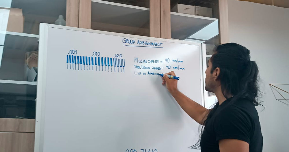
group assignment: characterize the design rules for your in-house PCB production process
individual assignment: make and test a microcontroller development board
extra credit: personalize the board, extra credit: make it with another process
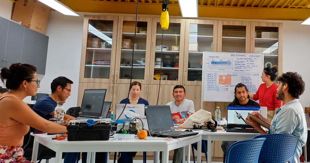
Group assignment
the group assignment was carried out at the facilities of the "Universidad cientifica del sur" in the fab lab.
For the group task we planned how we would perform a milling test from an image in .PNG format that we downloaded from the academy work files.
You can see the complete documentation on the group's web page
what did i learn in the group assignment?
The importance of having PNG files correctly plotted
The ease with which the Mods platform allows us to make the traces.
The CNC is easy to operate, just be careful when interchanging the milling tools.
We must be careful when calibrating the "Monofab" CNC Router.
Choose the right milling tools for each process to be carried out.
Individual assignment
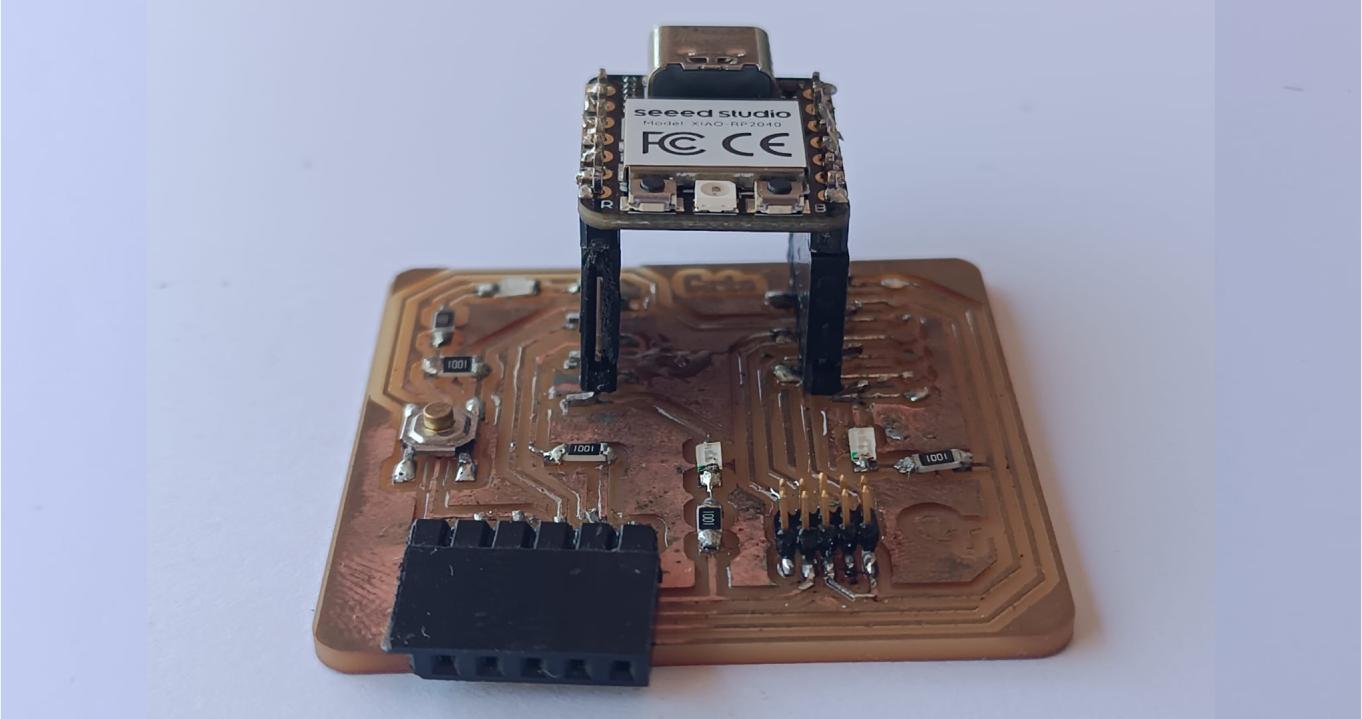
This time I will build option 2 where the XIAO RP2040 can be removed using the following connectors.

This is the list of all the components required to build the Quentorres pcb.
| Item | Components | Amount |
|---|---|---|
| 1 | SEEED STUDIO XIAO RP2040 | 01 |
| 2 | CONN HEADER SMD 10POS 1.27MM | 01 |
| 3 | CONN HEADER SMD R/A 6POS 2.54MM | 01 |
| 4 | Tactile Switch SPST-NO Top Actuated Surface Mount | 01 |
| 5 | LED BLUE CLEAR 1206 SMD | 03 |
| 6 | RES 1K OHM 1% 1/4W 1206 | 04 |
| 7 | RES 499 OHM 1% 1/4W 1206 | 01 |
| 8 | CONN HDR 7POS 0.1 TIN SMD | 02 |
All these components are located in Jr. Paruro in downtown Lima, Peru.

to locate us, we use google maps. click to see the google map with the coordinates.

We download the .png files of the PCB Quentorres
You can review all the documentation of the PCB Quentorres on its website
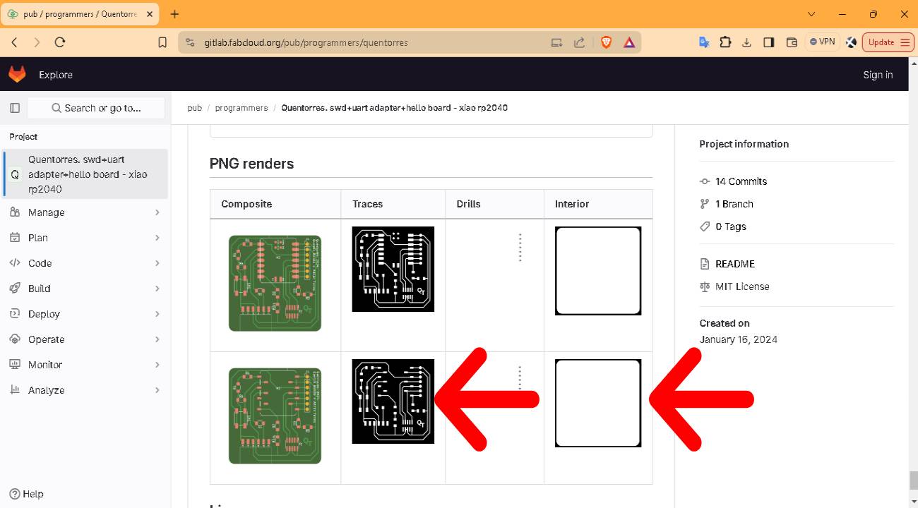
Now we will prepare the cut files starting from the .png files.
We will use the "modsproject.org" platform.
To use this tool just go to their website
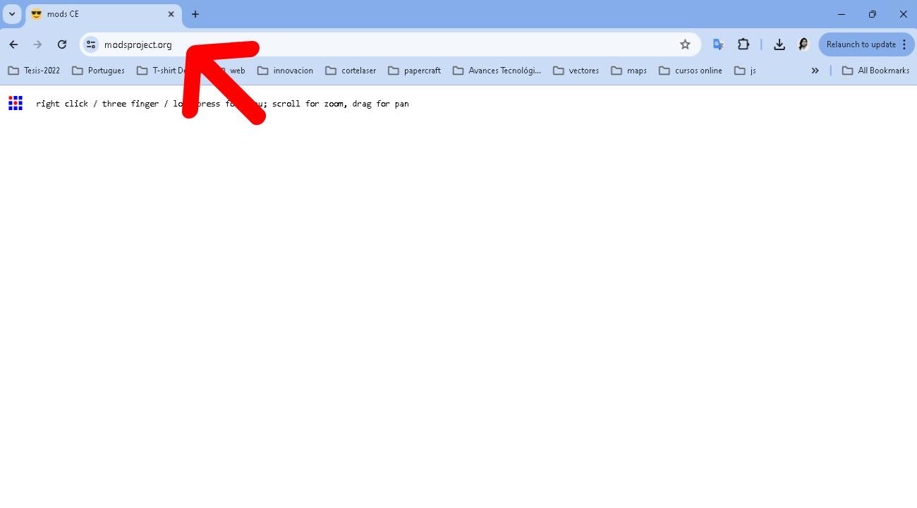
For the modsproject to work well, you must use the Google Chrome browser.
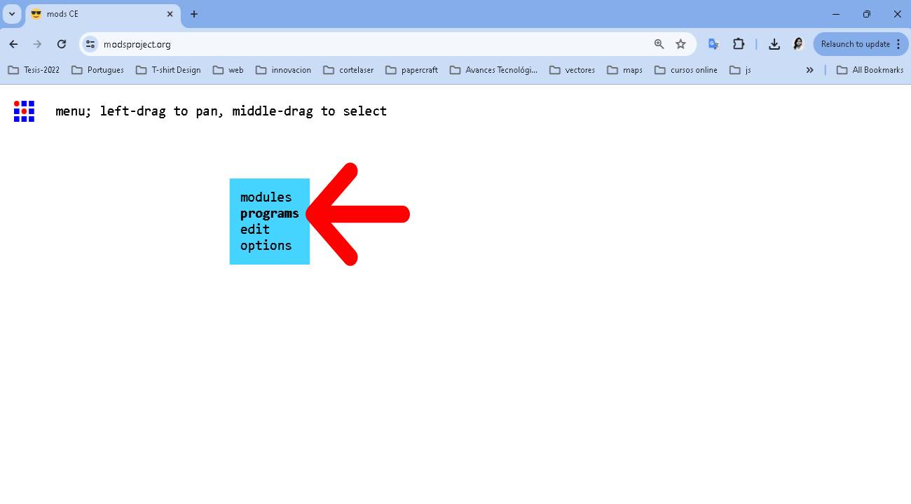
We right click to display the menu and select programs.
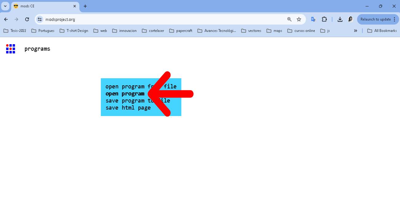
Select Open Program
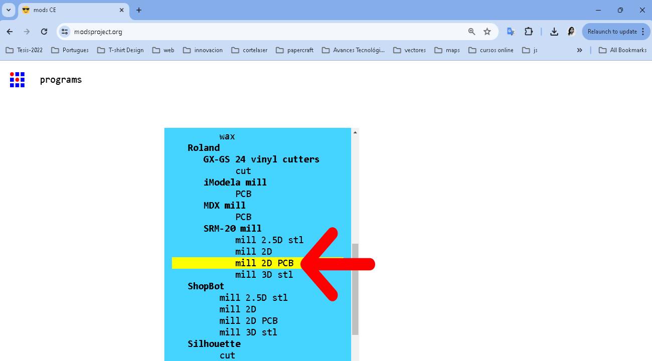
In the Roland -> SRM-20 Mill select "mill 2D PCB
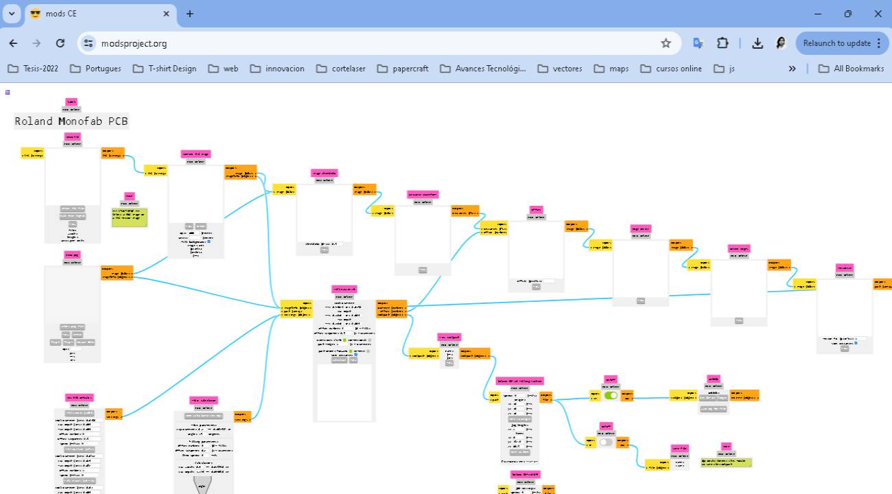
This is the environment that is loaded. It looks complex but it is easy to use.
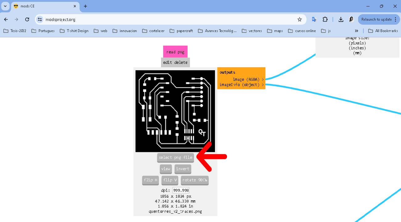
In the "read png" option, We select and load the .png file
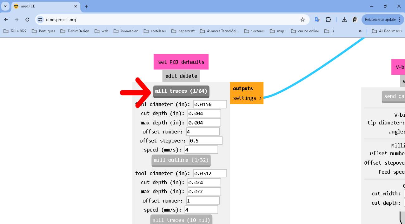
In the "set PCB defaults" option, we select the milling process "mill traces (1/64) with the predefined values.
In the "mill raster 2D" option we click on the calculate option, leaving the default options.
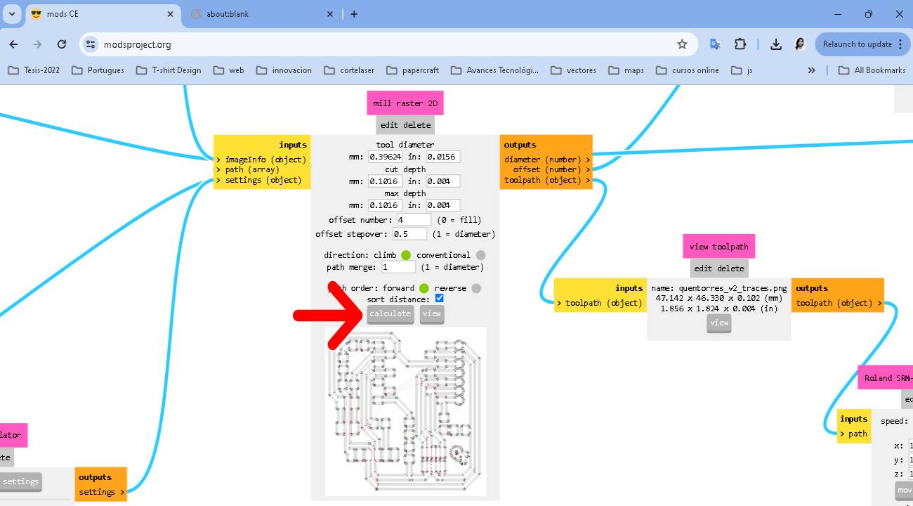
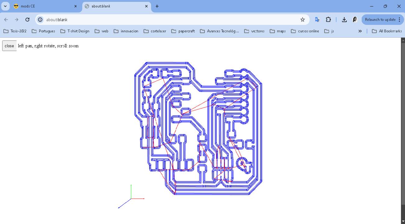
When it finishes calculating, it will show us a preview of the layout.
If everything is fine, we continue with the next process.
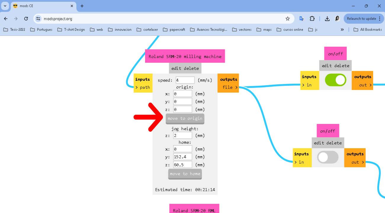
In the "roland SRM-20 milling machine" option we change the origin to 0 in X,Y,Z and select move to origin and leave the other values as default.
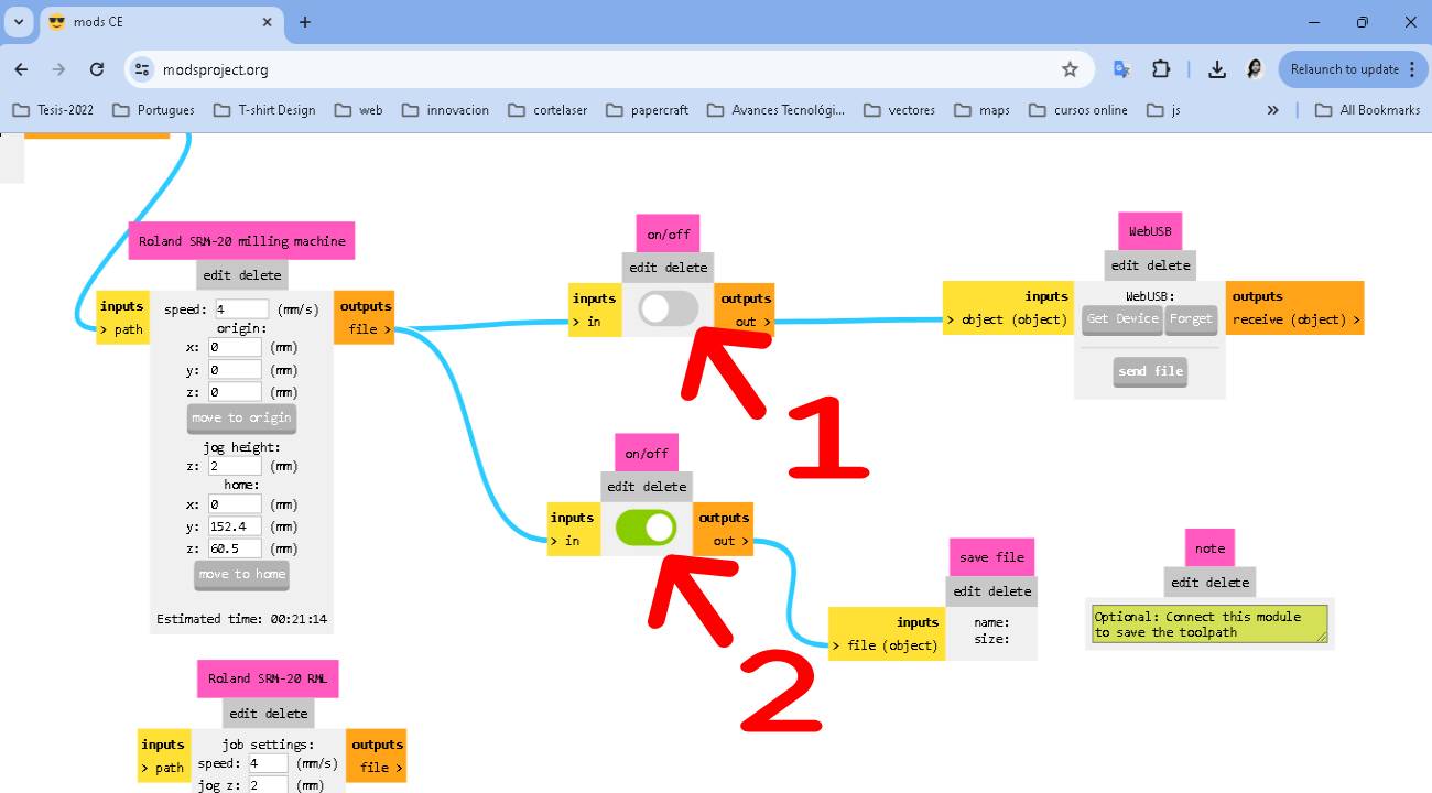
1. we deactivate the "webUSB" option.
2. We activate the "save file" option.
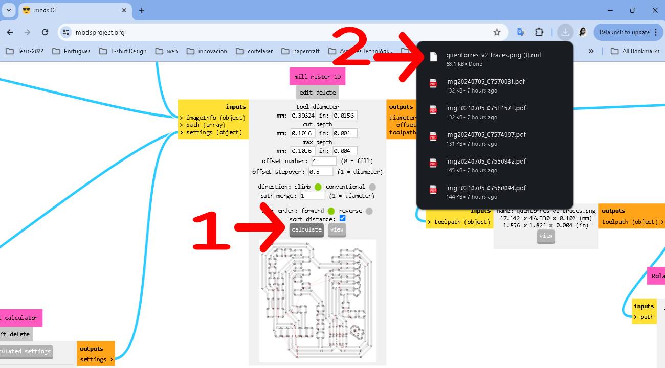
We return to the "mill raster 2D" option.
1. We click on the calculate option.
2. We see that it automatically downloads the file for milling.
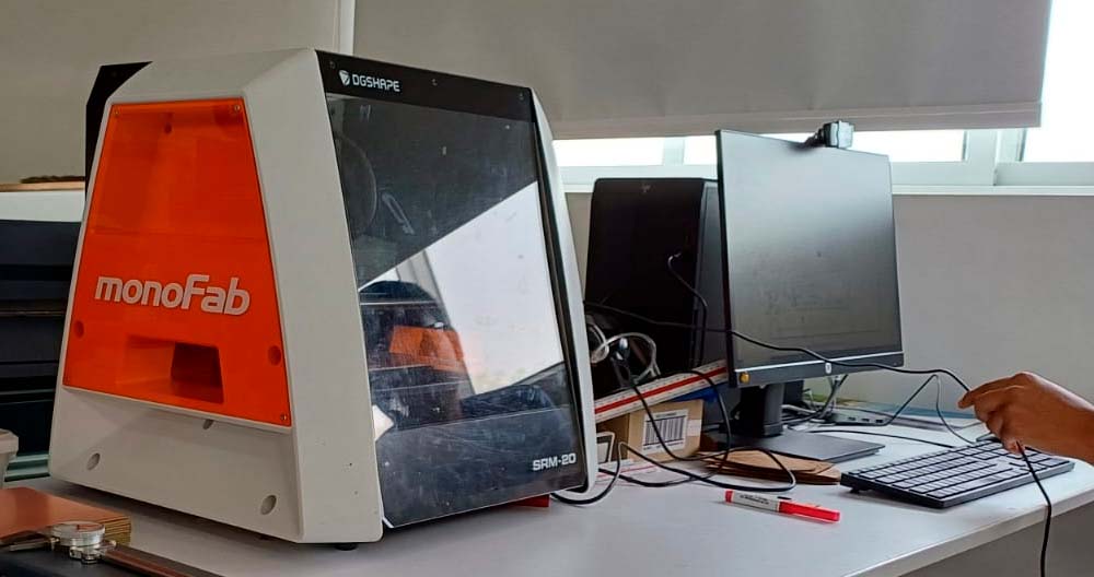
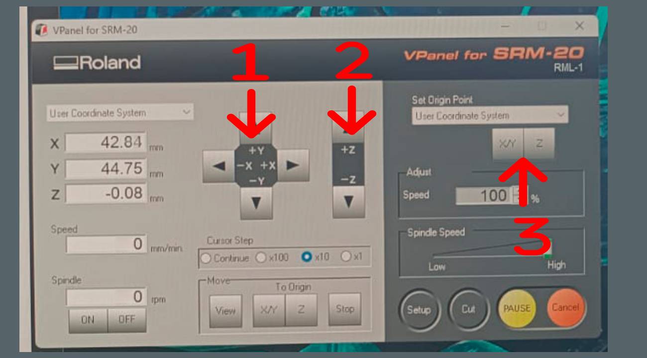
Now we configure the origin in the MONOFAB VPanel
1. We move the XY axis until we find the point where we want to start.
2. We move the Z axis until we are at the point where we will start.
3. Once located, we click on XY - Z of the "Set Origin Point" option to define the origin and it becomes X=0, Y=0, Z=0.
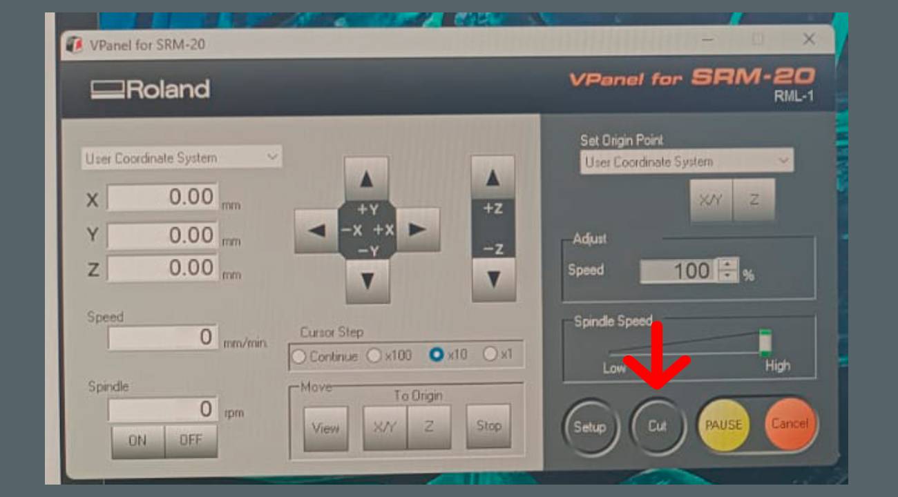
Once the source is configured, we click on the Cut option, add the file and finally click on Output.
Accessories: mills 1/64 mill used for milling and 1/32 mill used for cutting

PCB setup process for cutting.

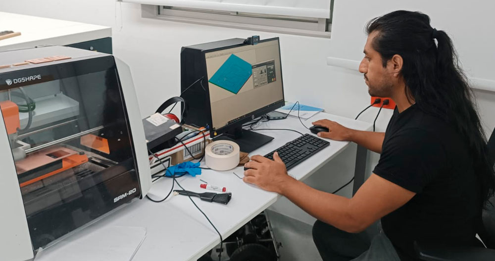
workstation Mono Fab SRM-20 Milling Machine.
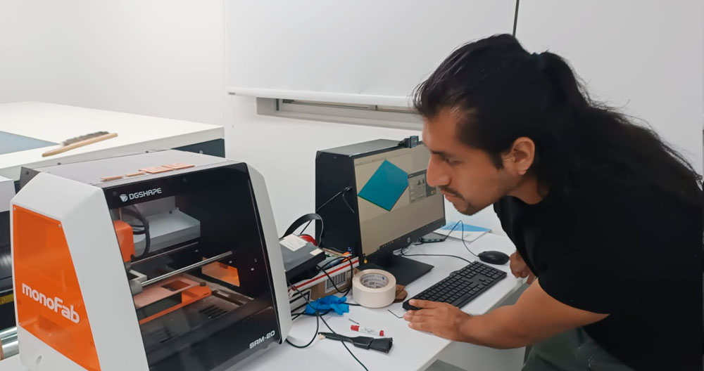
checking that the cutting process is working well.
first test was unsuccessful, we configured once again...
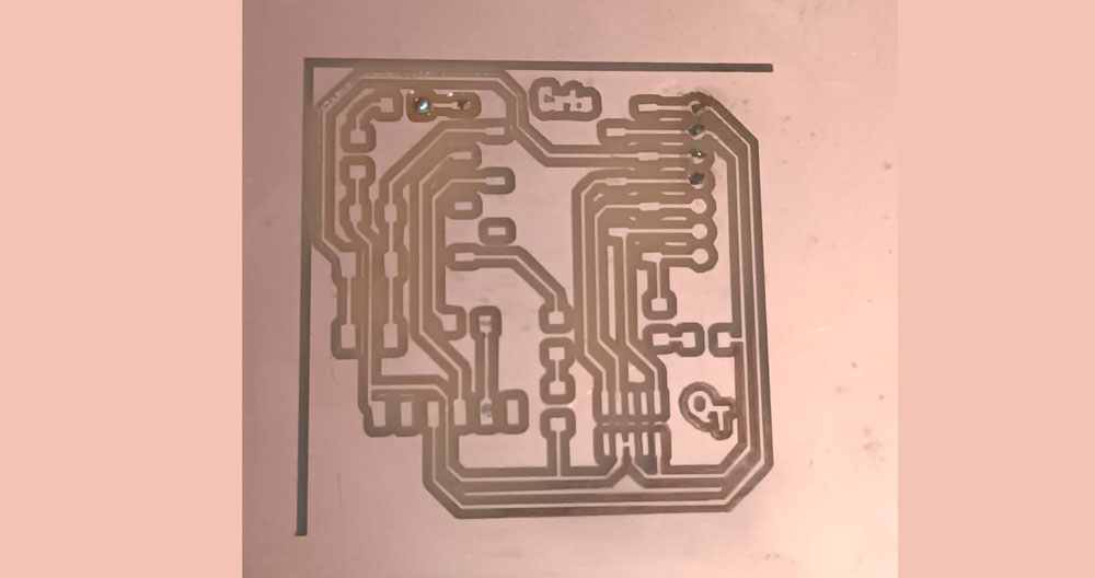
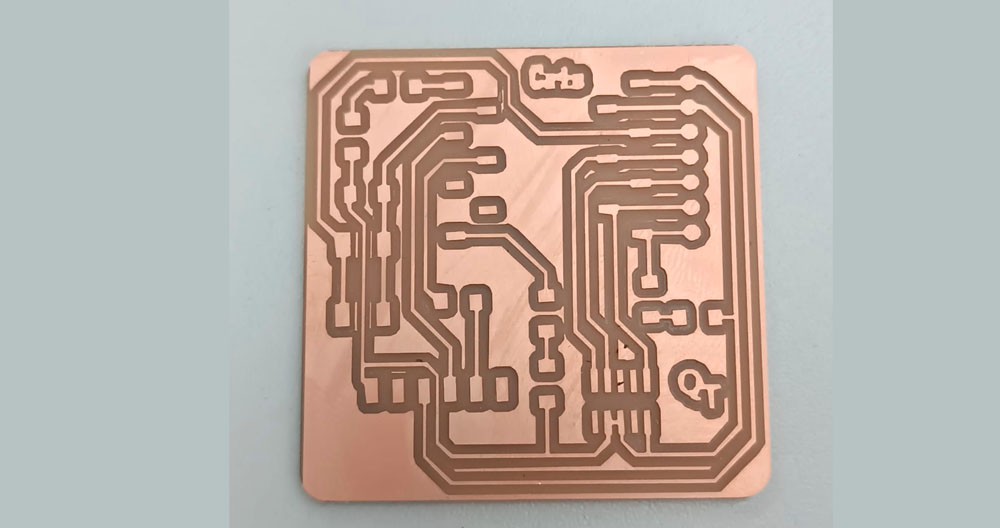
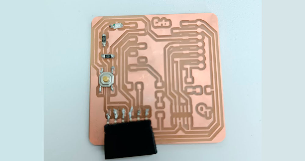
final result of the PBC Quetorres, this personalized with my name, I love it!!!!
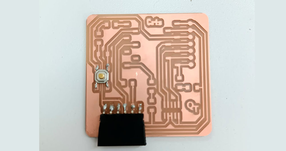
once the QUENTORRES is manufactured we proceed to solder the components, it is a job of great precision since I have no experience in this process.

It took me many hours to solder some of the components, I did not finish, but I will continue working on this process until the QUENTORRES is working.
Second component
Third component
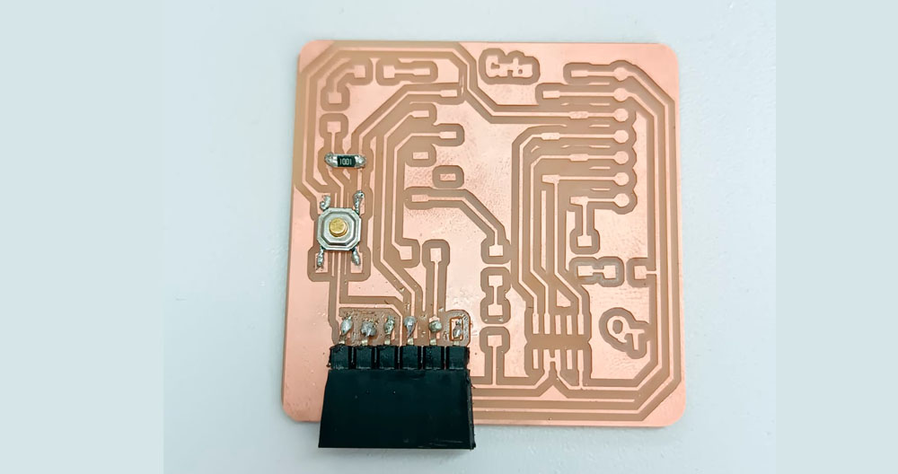
fourth and fifth component
Continuity test
After many hours I managed to solder all the components...

It is not perfect but it works...blood, sweat and tears....
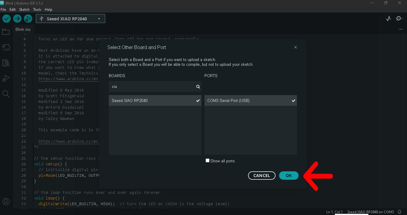
We use the arduino IDE to program the LEDs to turn on and see that the PCB works.
Select the board and select the ports.
Programming on and off of the 3 LED lights.

LED power-on test, it works!!!! I'm excited....
Download files
Here we can find and download the design original files