Wildcard Week
Objectives for Week 15
- Design and produce something with a digital process (incorporating computer-aided design and manufacturing) not covered in another assignment, documenting the requirements that tour assignment meets, and including everything necessary to reproduce it.
This week was all about trying our hands on machine that was not particularly used throughout the course. And I chose Wire EDM (Electrical Discharge Machining) machine. I haven't used the machine before but I have seen many videos and references showcasing zero tolerance capability that can be achieved by this machine and I was curious to try out a design showcasing the same effect.
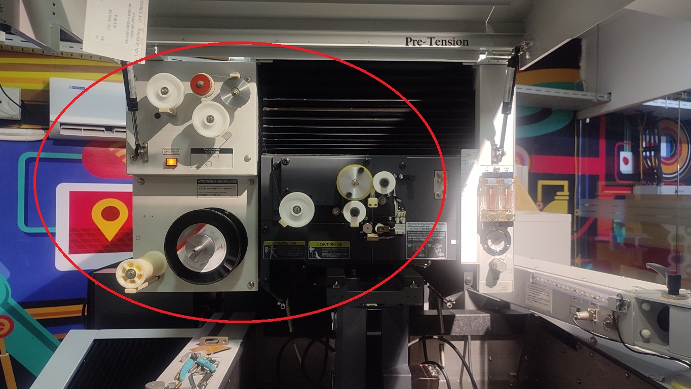
Mitsubishi MV1200-S Advance
.jpg)
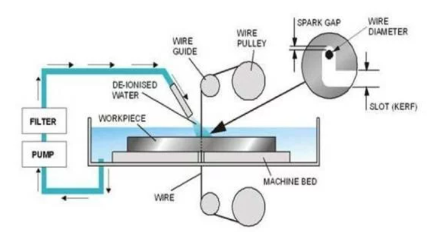
Wire EDM (Electrical Discharge Machining) is a specialized manufacturing process used to cut hard metals that are difficult to machine with traditional techniques. This process uses electrical discharges (sparks) to cut through material, offering the ability to produce intricate and precise contours with a high degree of accuracy.
Working of Wire EDM
A thin wire, usually made from brass or stratified copper, serves as the electrode. This wire is continuously fed from a spool through the workpiece, submerged in a tank of dielectric fluid (usually deionized water), and is continuously moving to ensure that it doesn’t wear out at any one spot during the cutting process. The wire is charged to a voltage that creates an intense electric field between the wire and the workpiece. When this electric field reaches a certain strength, a spark jumps across the gap, melting and vaporizing a tiny bit of the workpiece. The surrounding dielectric fluid helps to cool the process and flush away the removed material, keeping the cutting zone clear and preventing the metal from re-adhering. It also insulates the wire and workpiece, controlling where the sparks can occur. The machine is controlled by a computer that dictates the movement of the wire on a programmed path. This allows for very complex and detailed cuts to be made with precision.
Features:
- Machine Travel: 400 x 300 x 220mm
- Maximum Workpiece Dimensions: 810 x 700 x 215mm
- U/V Travels (from center): ±60 x ±60
- Taper Angle at Thickness: 45° at 1.8"
- Wire Diameter Possible: 0.1-0.3mm
- Auto Threader Technology: It features an improved non-contact Cylindrical Drive System with a non-contact auto-threading system, which allows for fast threading and re-threading of the wire, enhancing productivity. Here, we are using brass wire of 0.25mm thickness.
- Improved Cutting Speed and Accuracy: The MV1200-S Advance boasts high cutting speeds and excellent surface finish quality, making it suitable for demanding applications in aerospace, tool and die, medical, and other industries.
- Energy Efficiency: This model is designed with energy-saving features, reducing power consumption compared to older or less advanced models.
- User-Friendly Controls: It includes Mitsubishi’s M700 series control system, which provides a user-friendly interface, advanced programming capabilities, and easy integration with CAD/CAM systems.
- Advanced Filtration System: The machine incorporates an advanced filtration system that helps maintain clean dielectric fluid, crucial for maintaining the precision and quality of cuts.
.jpg)
Advantages:
- Excel at producing intricate and complex shapes that are difficult or impossible to achieve with conventional machining methods. They can cut fine details with high precision.
- Involves no direct contact between tool and workpiece and uses electrical discharges to cut the material, it can easily handle extremely hard materials like titanium, hastelloy, and hardened steel without tool wear.
- The non-contact nature of wire EDM means there is no mechanical stress imparted to the workpiece, which is crucial when working with delicate parts.
- Wire EDM machines provide high levels of accuracy and consistency, making them ideal for industries like aerospace, tool and die making, and medical device manufacturing.
- The machine is capable of achieving excellent surface finishes, reducing or eliminating the need for post-processing.
- Wire EDM can produce very thin walled configurations and fine meshes, which are challenging for most other machining processes.
Disadvantages:
- Wire EDM can only be used with electrically conductive materials, limiting its applicability compared to methods that can handle a broader range of materials.
- Compared to traditional machining methods like milling or turning, wire EDM is generally slower, particularly when cutting thicker or harder materials.
- The cost of operation can be high due to the wear and replacement of consumables such as the wire itself, as well as maintenance of the dielectric fluid and filters.
- EDM machines typically consume a significant amount of electricity, impacting operational costs, especially in regions with high energy rates.
- Setting up for wire EDM can be time-consuming, especially for complex cuts or when high precision is required.
- While capable of handling a range of sizes, wire EDM machines have practical limitations on the maximum size of workpiece they can accommodate, constrained by the dimensions of the machine tank and wire travel.
Design
I tried creating a simple design using Fusion 360. Since, my main aim is to create zero tolerance piece, I focused on creating two parts accordingly.
I gave a clearance of 5 microns between the pieces. And I was also instructed that since my design is quite small, I won't possibly get the sharp edges, so I gave a fillet of 0.125mm (half the diameter of the brass wire) at all the edges in both my pieces.
Next step is to generate .dxf files for cutting. I first created a single file containing the projected profiles of both the pieces. For machining in EDM, we have to set origin points and insert the thread there. So for that, before placing we have to drill holes at those origin points.
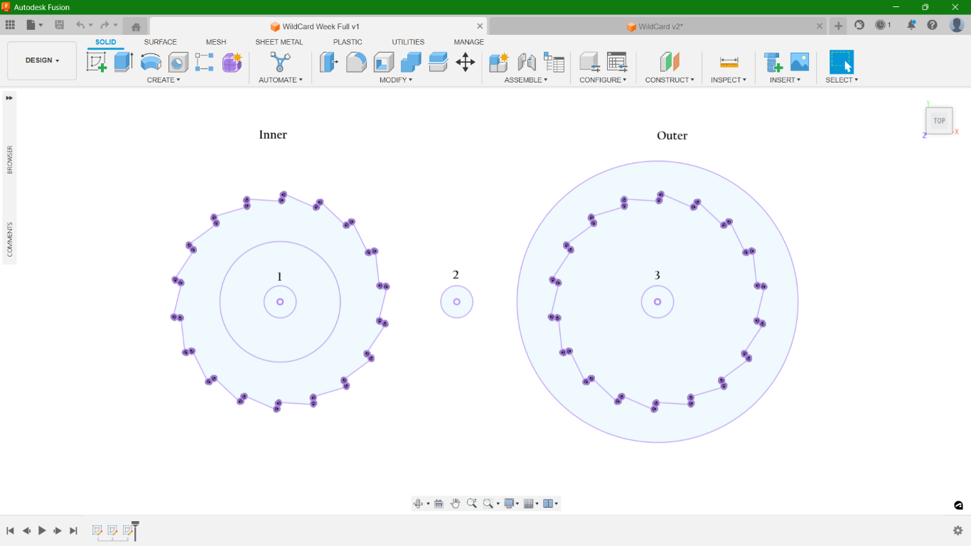
Here, you can see three circles. We insert the wire through these holes according to the parts and set them as the starting points for each cutting operation.
Drilling
For my work, I'm using Aluminium block 160x37x16mm. In order to drill the holes, I used DPM RX2 Vertical Milling Machine. CAM for the same was done in Fusion 360.
Refer documentation of Week 12 to know how to set the CAM and how the work setup is done. Here, I used 3.5mm drilling bit for the holes.
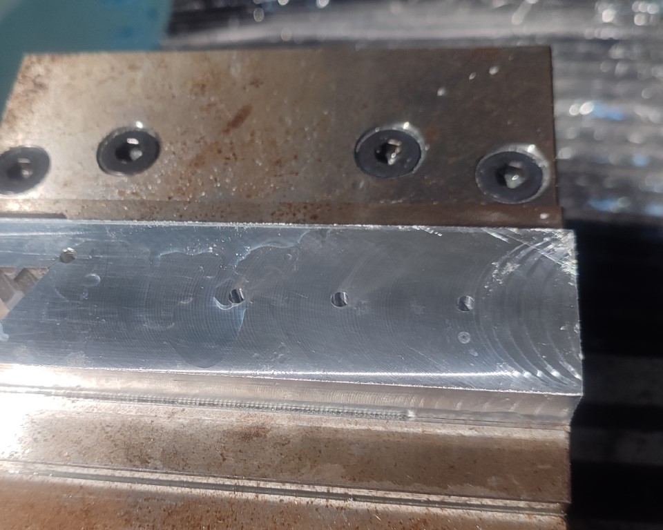
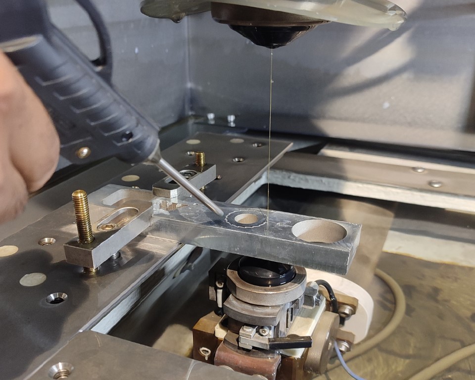
Work Setup
To set the workpiece on EDM, I used clamping tools.
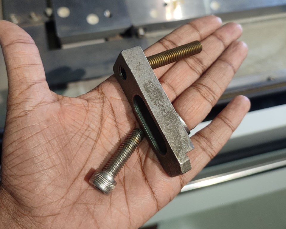
Using two sets of the same, the workpiece was clamped on area provided.
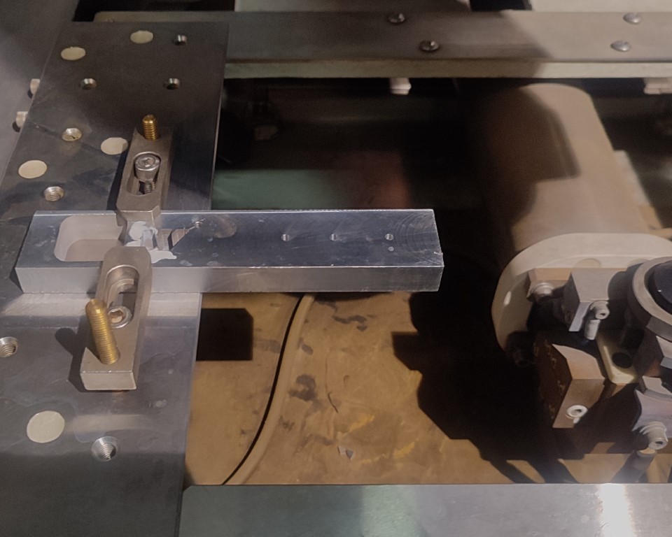
While clamping the workpiece there is higher chance that the orientation of the workpiece is not proper ,i.e., there will be a slope. The machine has a feature where it can measure the slope and adjust the cutting file accordingly.
Next, switch on tha machine. There are two things that should checked mandatorily before proceeding to operations.
1. The value of Specific Electrical Resistance is in the normal range.
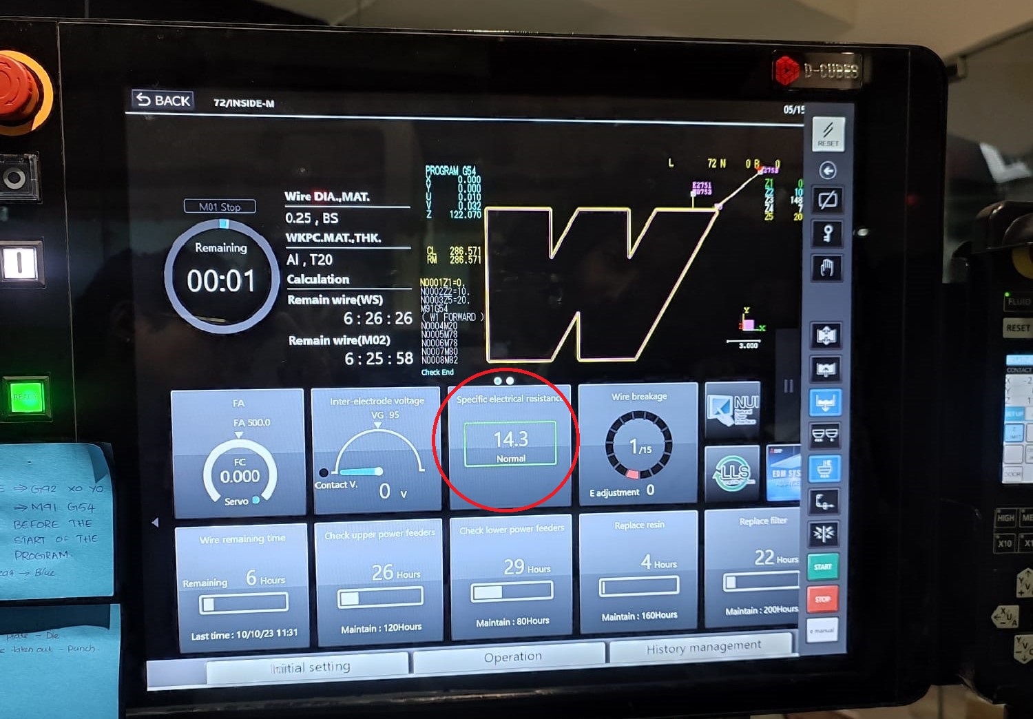
2. The button G92Clear on top is in blue colour. Otherwise, click on Reset till its blue.
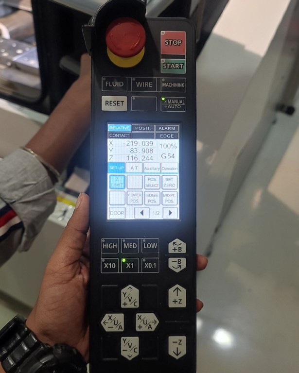
The Mitsubishi MV1200-S Advance comes with a pendant. It essentially the control interface that the operator uses to interact with the machine. This pendant includes various controls and displays necessary for operating the machine, setting up jobs, and monitoring the process. It's a critical component as it allows for precise and easy manipulation of the machine's functions.
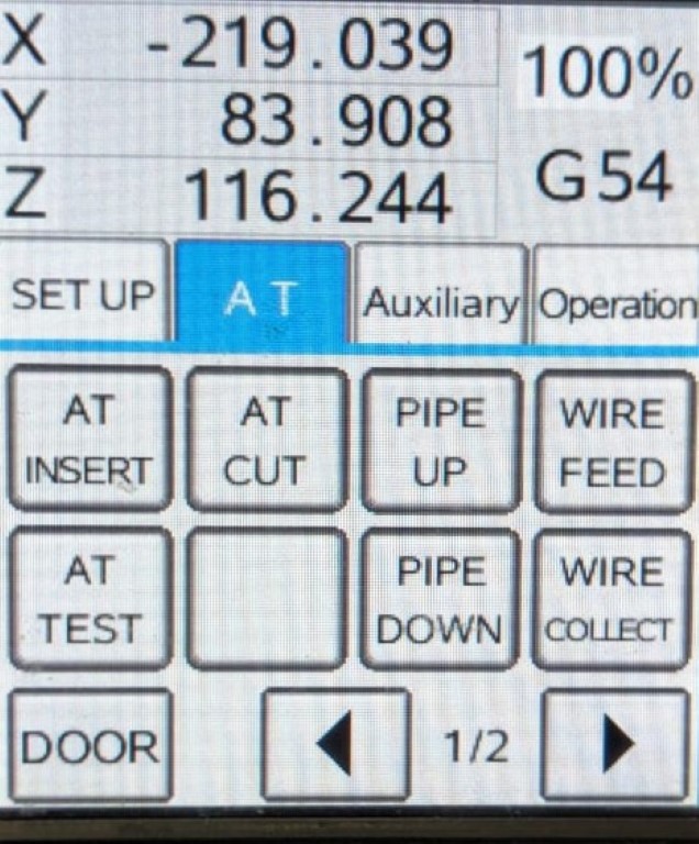
• AT Insert: To insert the thread automatically
• AT Cut: To cut the thread
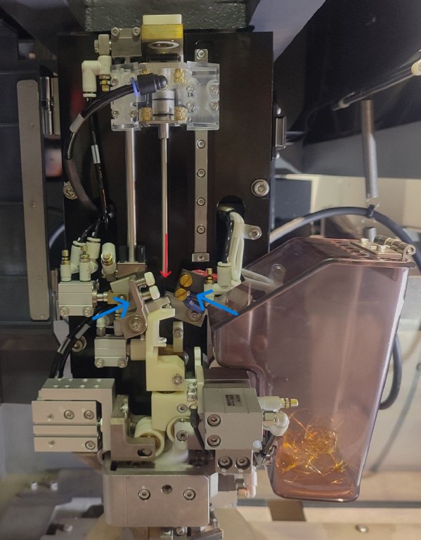 The parts shown with blue arrows closes holding the wire in between them.
A spark is seen while the wire is being cut.
• AT Test: While orienting the nozzle to the hole to insert the thread, by pressing
this button, water will flow down through the nozzle thereby making it
easier to position the nozzle right through the hole.
• Pipe Up and Pipe Down: To manually insert the wire during failure in AT Insert
The parts shown with blue arrows closes holding the wire in between them.
A spark is seen while the wire is being cut.
• AT Test: While orienting the nozzle to the hole to insert the thread, by pressing
this button, water will flow down through the nozzle thereby making it
easier to position the nozzle right through the hole.
• Pipe Up and Pipe Down: To manually insert the wire during failure in AT Insert
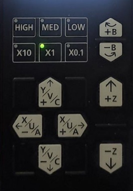
    • High, Med, Low: To set the speed of the movement of the nozzle while
                              manually moving
    • +X, +Y, +Z and its negatives: To move the nozzle in corresponding axes
Calculating Slope
After placing the workpiece, in order to measure the slope, first we press on AT Insert to load the wire. Next, click on Work Slope option available at "Work Setup".
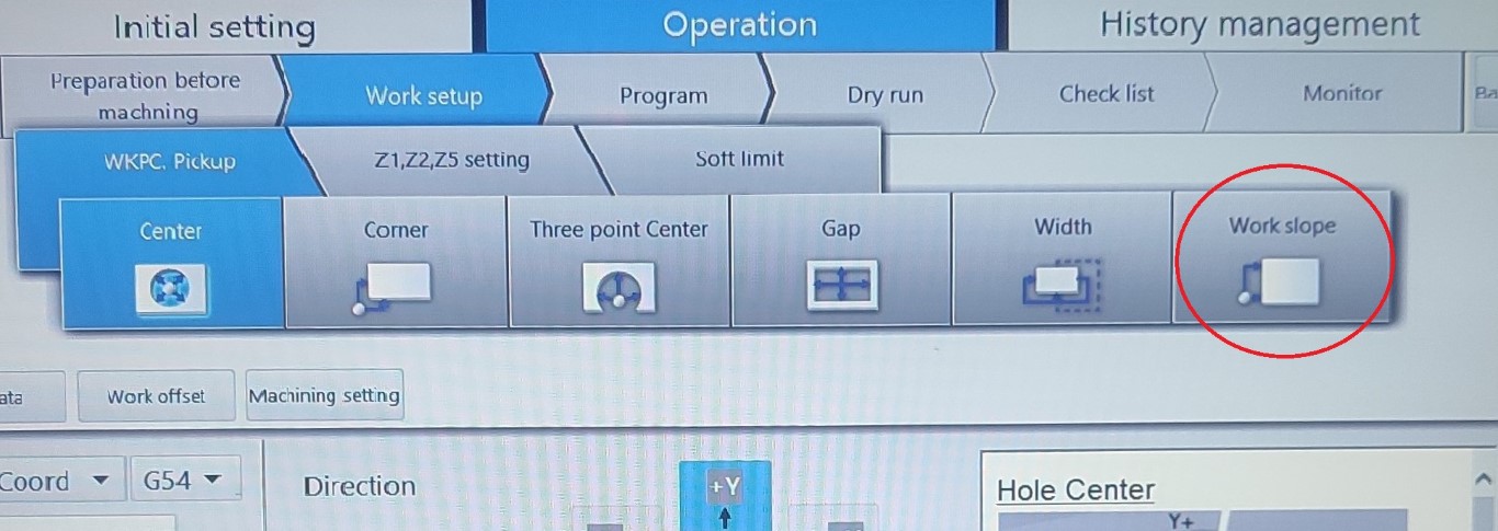
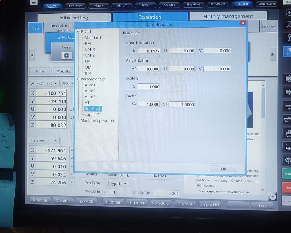
Next, select the progress method required according to the placing of the workpiece and press on "Start" in the pendant to find the slope. Once done, click on Machining Setting > Rot/Scale to see if the value of K (slope) is set.
Calculating Origin
Before starting each operation, the origin or the starting point has to set. In this case, I have already drilled the holes from where the operations are to begin. For that, first we move the nozzle right above the circle with the help of Pendant. to see if it is on the correct position, press on "AT Test" to see if the water pass right through the hole. If it is proper, then insert the wire with "AT Insert".
Next, click on Work Setup > Center to find the center of the circle. Make sure to give the position angle as 20.0 deg. One more thing to notice, while giving input number make sure to add the decimal point right after since it doesn't store the value otherwise. For example, here I gave 20.0 deg instead of 20 deg.
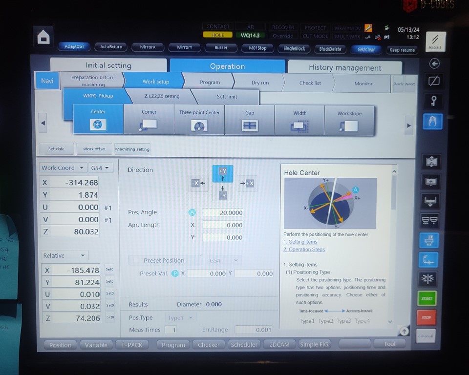
Press on "Start" after providing the detail and once completed, set the value of X and Y coordinates as 0.0
CAM
Next step is to do the CAM for the operations. Click on 2DCAM at the bottom of the screen.
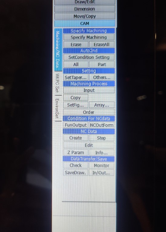
Click on "File" to insert the .dxf file. At the right side, there are different options available. Click on Specify Machining.
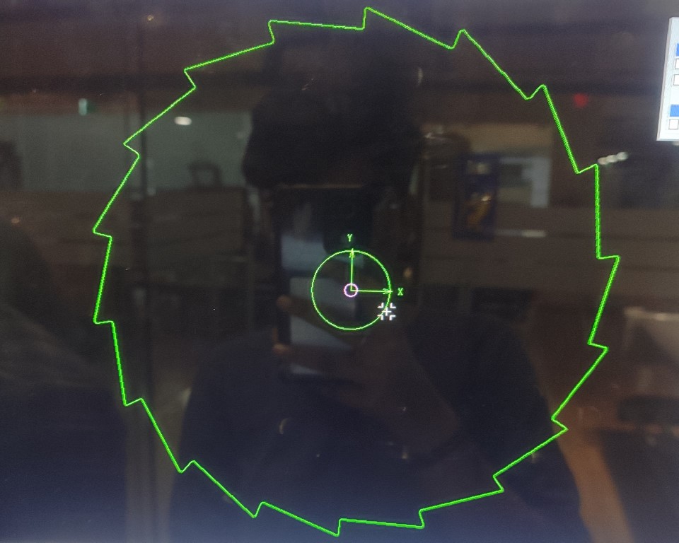
Press on Shift and then move the cursor to the circle to see a crosshair appearing and then click on it to define the starting point. Next click anywhere on the profile that is closer to the starting point to show the path.
Next, click on SetCondition Setting to define the operation and workpiece material.
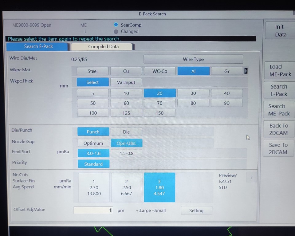
• Workpiece Material: Aluminium
• Workpiece Thickness: 20mm (Actual thickness of the block is 16mm, but it
is better to choose the closest value from the option)
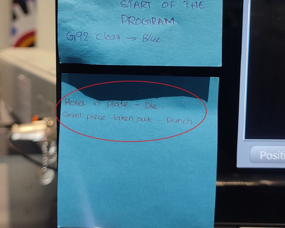
• Die/Punch: It depends on each operation. We have a note stuck to the
system in order to avoid the confusion between die and punch.😅
 • Nozzle Gap: I selected Opn-U&L where the upper and lower nozzle will
align itself to the gap.
• Find Surf: It defines the surface finish. Lower the number, greater the
surface finish. I chose 3.0-1.6 as it is enough for my work
and also because the lesser the number, more time-consuming the
operation becomes.
• No.Cuts,
Surface Finish and
Avg. Speed: Depends on the operation, If I'm cutting the outer portion, then
the surface finish need not be high. One pass would be enough.
But for the portion where the zero tolerance is to be achieved,
I gave the third option, i.e., 3 passes, so better surface finish.
• Nozzle Gap: I selected Opn-U&L where the upper and lower nozzle will
align itself to the gap.
• Find Surf: It defines the surface finish. Lower the number, greater the
surface finish. I chose 3.0-1.6 as it is enough for my work
and also because the lesser the number, more time-consuming the
operation becomes.
• No.Cuts,
Surface Finish and
Avg. Speed: Depends on the operation, If I'm cutting the outer portion, then
the surface finish need not be high. One pass would be enough.
But for the portion where the zero tolerance is to be achieved,
I gave the third option, i.e., 3 passes, so better surface finish.
Once data is provided, click on "Search E-Pack" and click "OK".
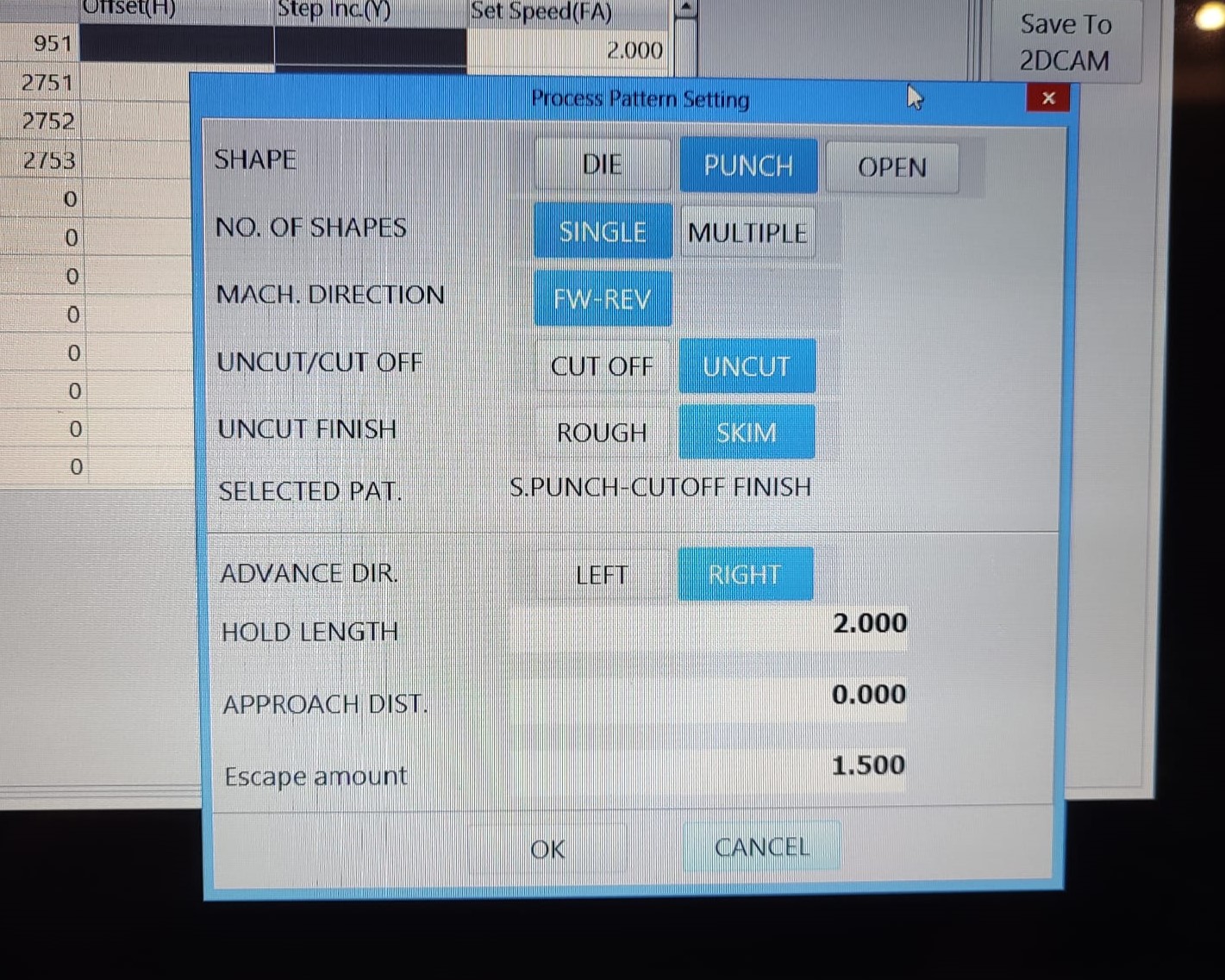
While saving, you have enter some of the data again and here you get the option to add tabs. I have only provided tab for the punch, since, it has three passes and the surface finish should be greater at all points. By giving tab, the machine will cut all the other path in 3 passes and then stops. during that time, we have to fix the punch to the outer so that it doesn't fall off hile the tab is being cut. Once fixed, pressing on "Start", the tab is then cut.
Then, after going back to 2DCAM, press All option under SetCondition Setting to apply the parameters to all profile.
Click on NC Data > Create to generate G-Code. Then, click on Data Transfer/Save to save the G-Code.
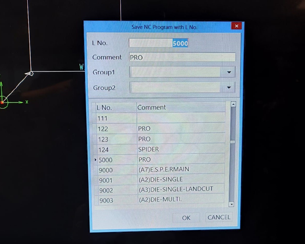
In the G-Code some edits has to be done. to do so, before saving, click on "Open File" and add M91G54 before the program and delete G92X0Y0 code from the file.
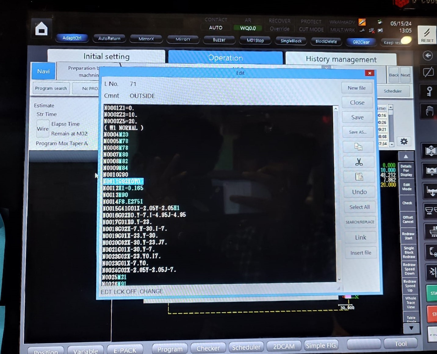
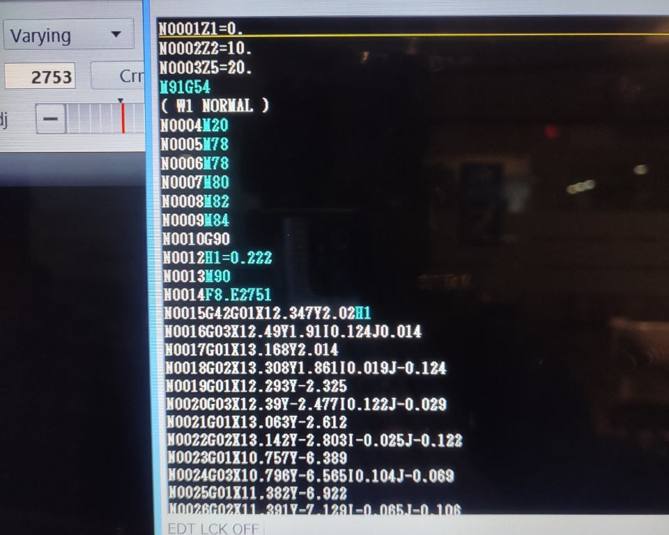
M91G54 is to set a predefined point as the origin for the part being machined. In this case, the center of the circle. The code G92X0Y0 is a command used in CNC (Computer Numerical Control) programming to set a temporary zero point or offset for the X and Y axes at the current position of the tool. Both the code typically serves the same purpose but we have been advised to choose the first because the latter can only be used in the situations where the initial point is set in which case if it is made to travel from one point to other, there is chance that the operation fails.
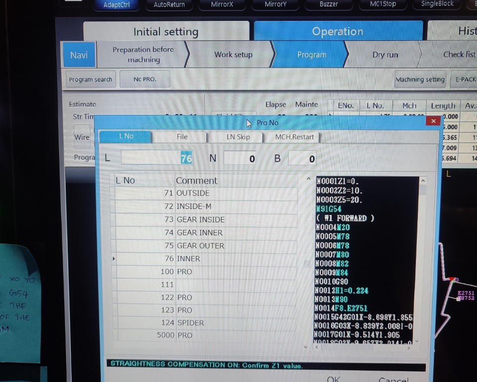
Next, open Program available at the bottom of the screen. Click on Program search to load the file.
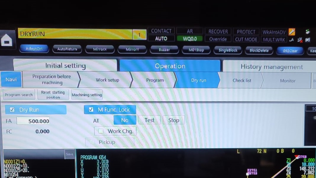
It is always better to try Dry Run first before moving to the actual machining. For that, click on Program > Dry Run and press "Start". You will be able to see the path so that you could clarify any errors.
If it turns out to be right, then next we have to set the Z limit. The upper nozzle should be as close to the workpiece. It can be achieved with the help of Pendant. Once it is closer, press and hold "Z limit" on the Pendant. Setting the limit is beneficial because once set, even if you change the Z position while taking out the pieces in between the process, while lowering down, it automatically stops at the set limit.
Once done, go to Program and press "Start" to start the process.
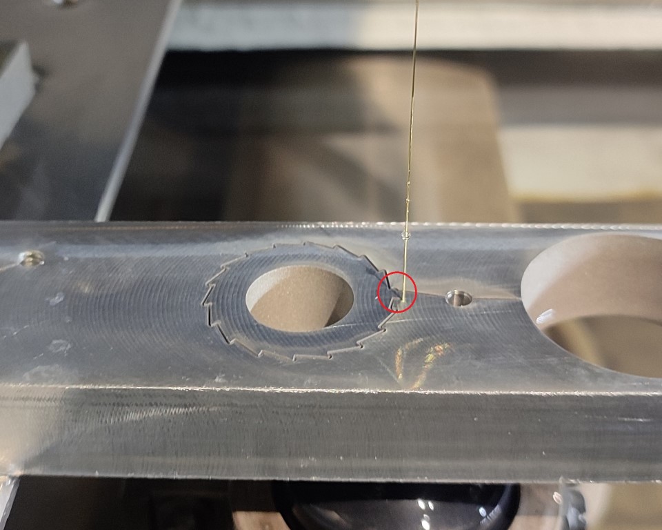
As each operation is done, the next .dxf file is added and the process is repeated. I had a total of 4 operations. Inner and Outer portions had to be cut from both the pieces.
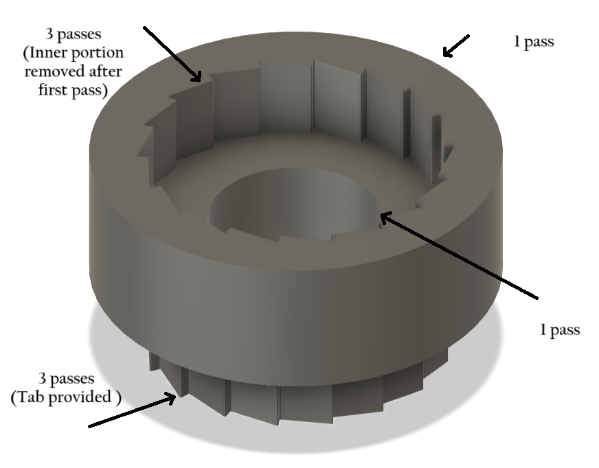
In this, for the inside of the outer piece, as the inner part is not required I didn't provide any tab. After the first pass, the machine automatically stops so that we could remove the piece manually and it then resumes the next two passes for finish. As for the inner part, since, the cut-off piece is required, I had provided tabs. What it does is, first it machines the all the other part except the tab in 3 passes and then stops. At this time, we have to fix other sides to the outer part so that it doesn't fall off while cutting the tab.
When the machine stops in between, with the help of pressurized air, we first clean the surface, then, I added copper strips with the help of flexkwik. Then resumes the work. The tab is then cut in 3 passes.
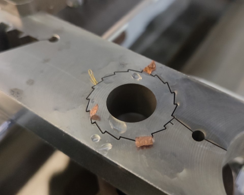
Result
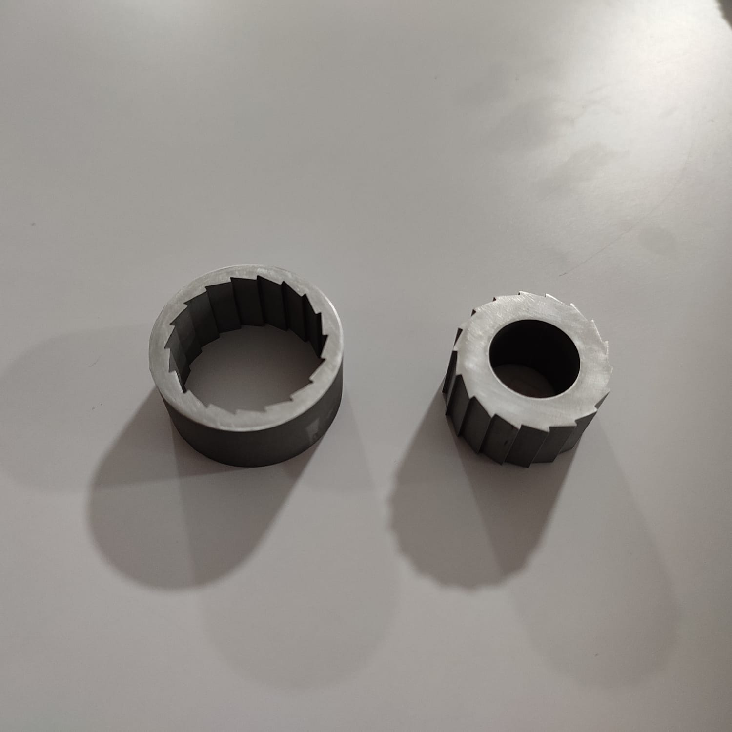
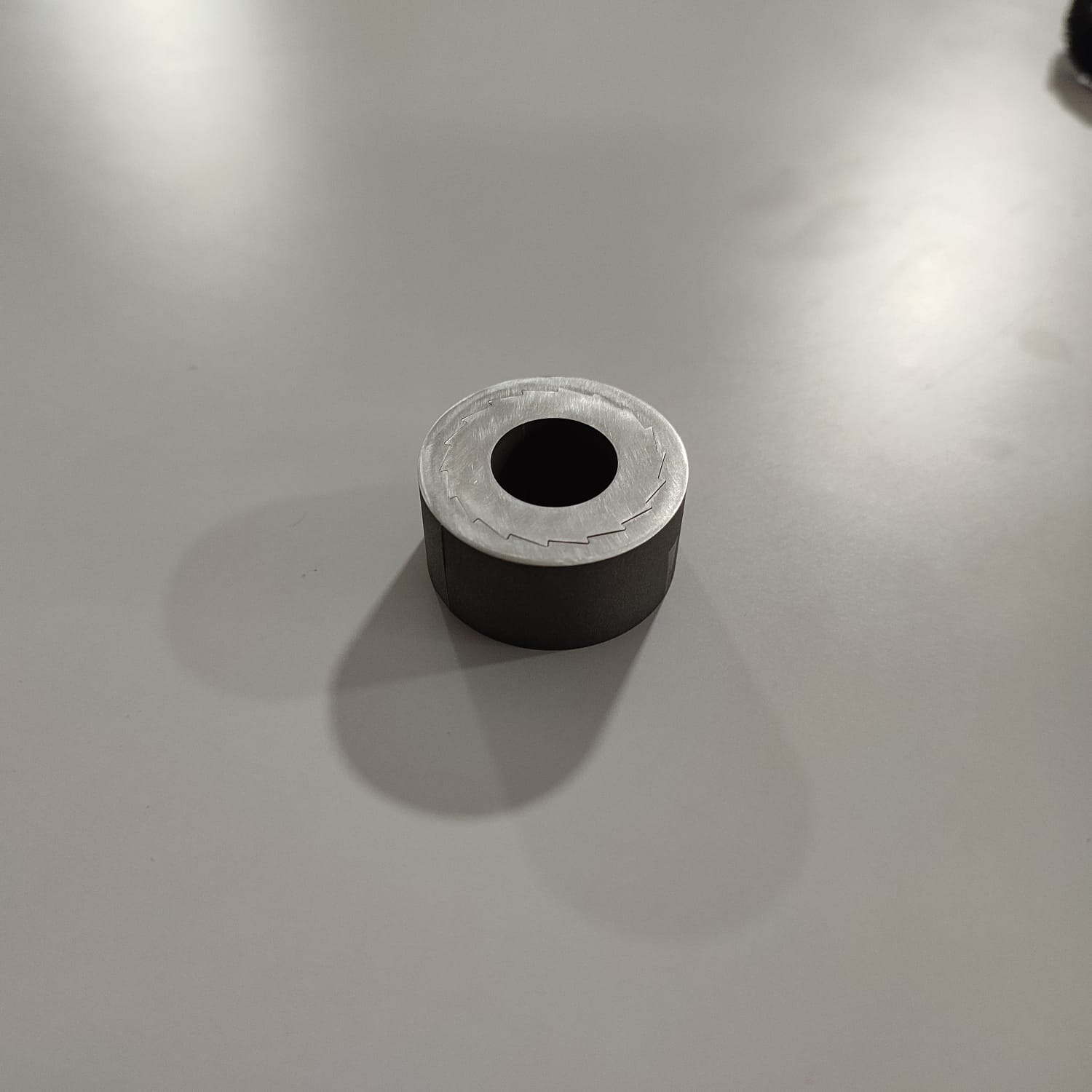
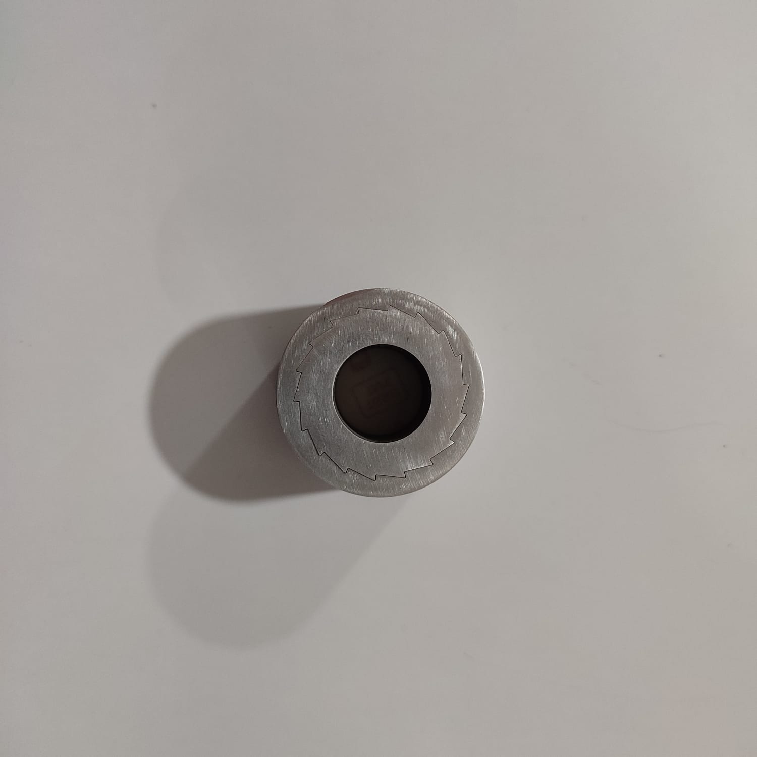
The result is not really satisfactory as the zero tolerance is not achieved since the edges of the pieces are evident.
Download Files
  • Design File (.f3d file)
  • Design File (.dxf file)
  • Design Files for EDM (.dxf file)