Molding & Casting
Objectives for Week 12
- Group Assignment:
- Review the safety data sheets for each of your molding and casting materials, then make and compare test casts with each of them
- Compare printing vs. machining molds
- Design a mold around the process we'll be using
- Produce it with a smooth surface finish and use it to cast parts
extra credit: use more then two mold parts
Group Assignment
This week's group assingment was to review the safety data sheets for each of the molding and casting materials and then compare their test casts and also to compare printing and machining molds.
For further details, click on the link below.
Group Assignment-Week 12This week was about creating a mold and casting on it. We were given two options; either create the mold using 3D printing or by 3D milling. I chose the latter since milling is more complicated and I didn't have much experience working with the machine so, I chose to learn.
Design
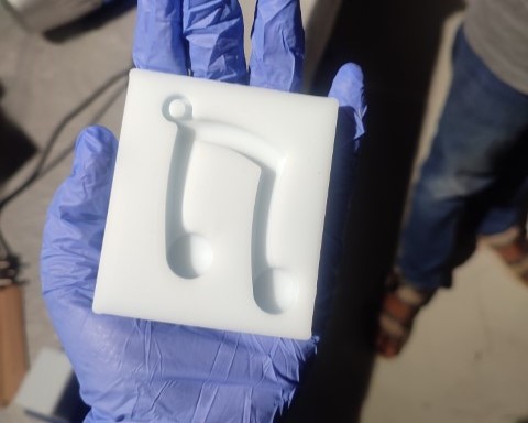
For design, I thought of creating a keychain inspired by the pendant I'm wearing that my mother gifted me when I was younger. It is a simple musical note. I designed the model in Fusion 360. The designing part wasn't that difficult.
This week, I gave more importance to CAM as it is my first time doing it in Fusion, therfore, I kept the design much simpler.
CAM
The CAM capabilities in Fusion 360 allow users to prepare their designs for manufacturing on a variety of machines, including CNC routers, milling machines, lathes, and more. Here, I'll be using the CAM for milling my design on a machining wax block using DPM RX 2 Vertical Milling Machine.
In Fusion 360, the CAM workspace is utilized for milling operations, enabling users to select cutting tools, set material properties, and determine machining parameters. Within this workspace, users can generate and adjust toolpaths that direct the cutting tool's movements. Additionally, the CAM workspace offers a simulation feature to verify the accuracy of the toolpaths and ensure that the machined product will align with the desired specifications. Once the toolpaths are finalized and validated through simulation, they can be exported as G-code. G-code is a programming language used to control CNC machines. This code can then be sent to a milling machine, guiding it to produce the intended physical part.
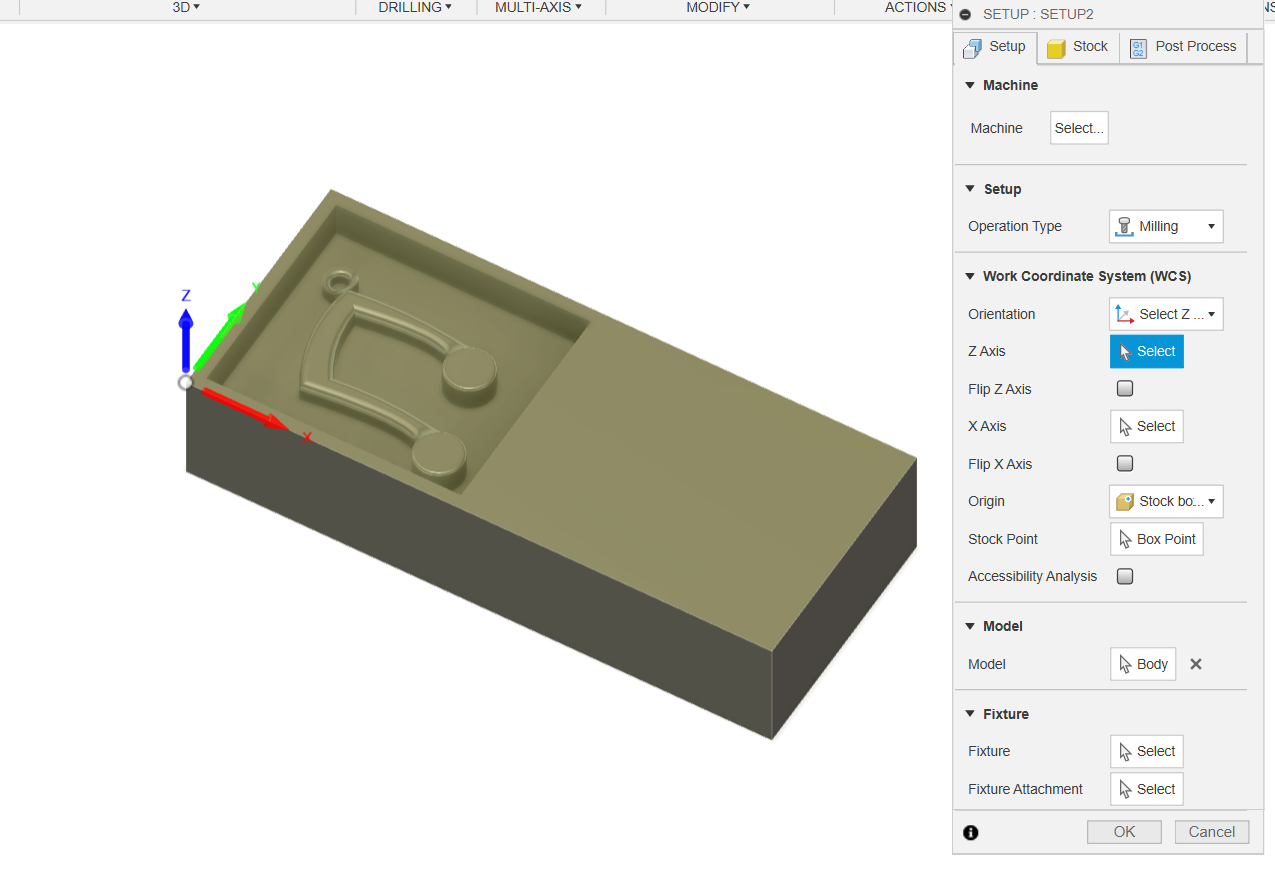
To access the Manufacturing workspace in Fusion 360, navigate to the dropdown menu in the Machining section and choose the Manufacturing Environment option. Once you're in this environment, you'll need to configure a few settings. Start by establishing the machining interface. You can do this by selecting Setup > New Setup.
The first step is to set the stock and the axes right. It is important to set the Work Coordinate Systems (WCS) offset as 1.
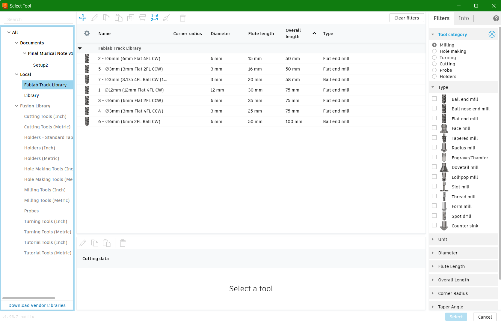
Once the initial setup is complete, the next step involves selecting the necessary tools for the project. To add tools to your tool library, navigate to Manage > Tool Library. I have incorporated the tool library from our FabLab, which includes all the tools currently in use.
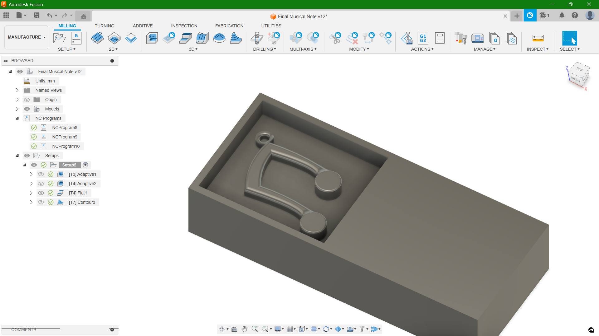
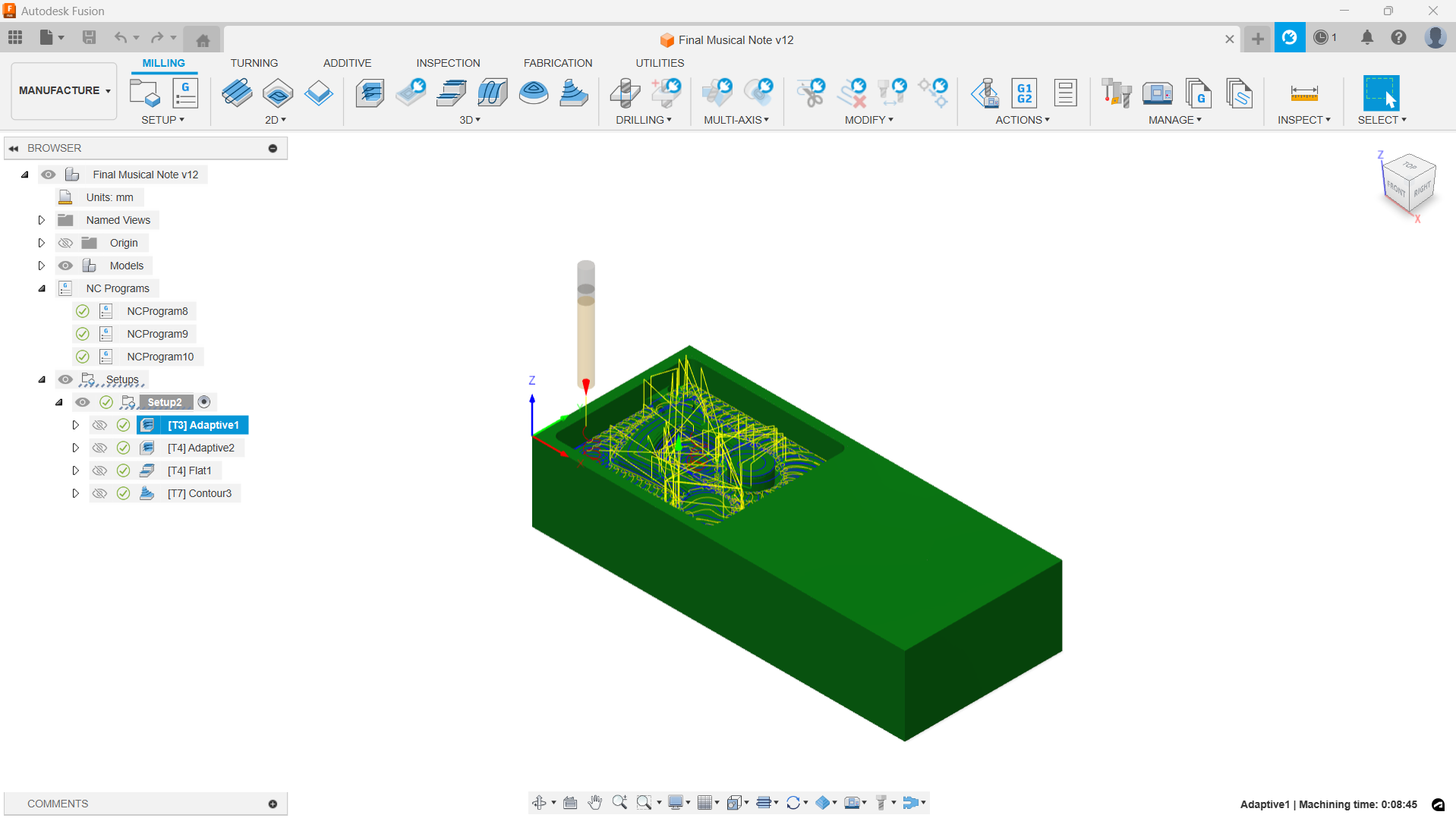
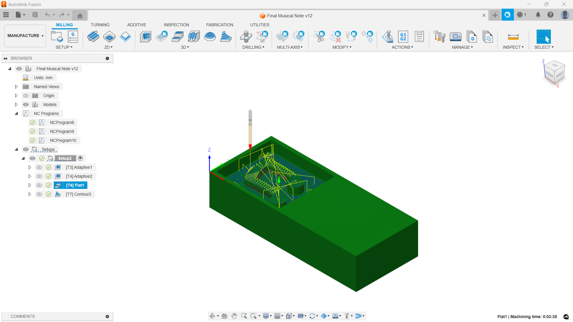
I chose 4 separate operations for my design milling. All the operations are under 3D from the toolbar.
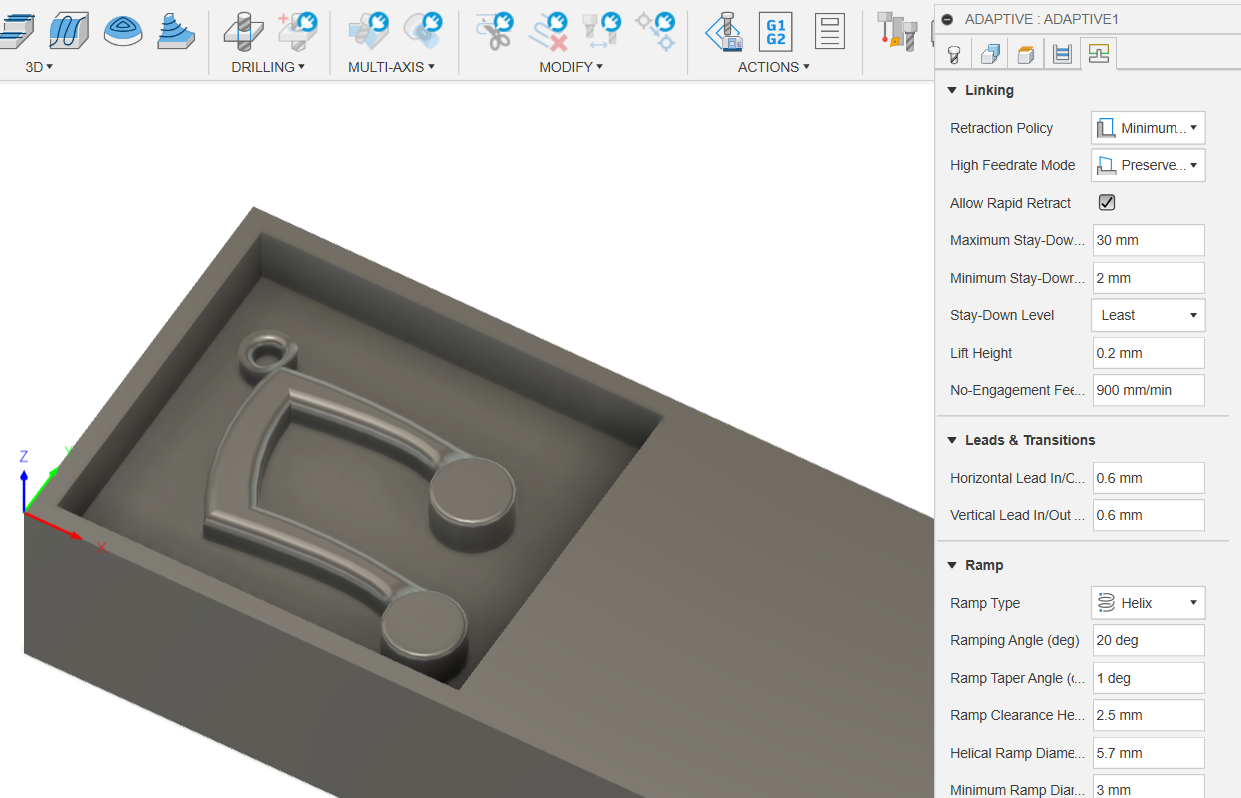
- Adaptive Clearing 1:
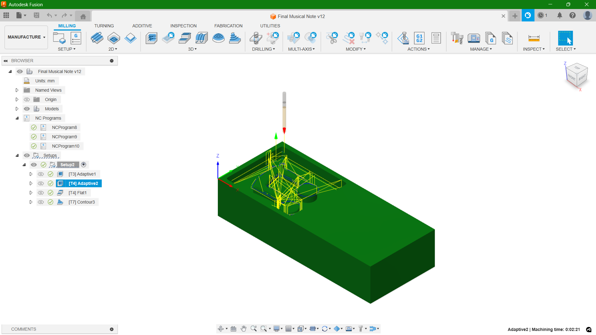
- Adaptive Clearing 2:
- Flat:
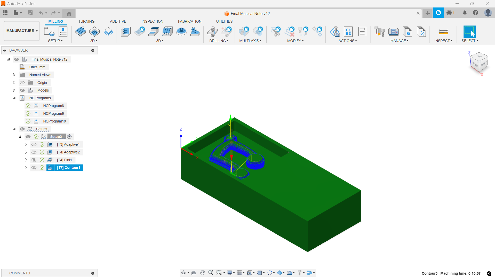
- Contour:
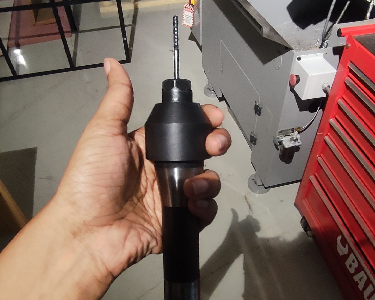
Mill Bit: 6mm Flat End Mill 2 Flutes
Mill Bit: 3mm Flat End Mill 4 Flutes
Mill Bit: 3mm Flat End Mill 4 Flutes
Mill Bit: 3mm Ball Nose Mill 4 Flutes
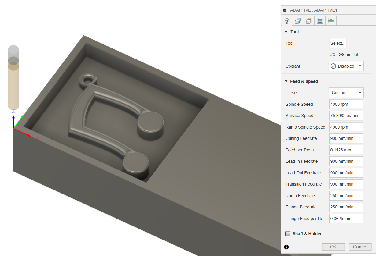
Additional Common Settings:
- Spindle Speed: 4000 rpm
- Cutting Feedrate: 900 mm/min
- Retraction Policy: Minimum Retraction
- Ramping Angle: 20 deg (for Contour: 2 deg)
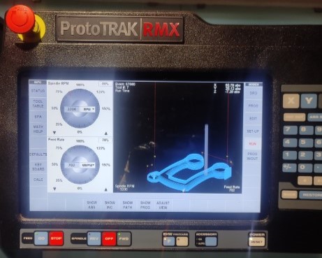
After setting each operation, by right clicking on the operation and selecting "Simulate", you'll be able to see the toolpath of each operation.
Once everything was ready, next step is to get the G-codes.To accomplish this, I right-clicked on the job and chose "Post Process." Next, I specified the location where I wanted to save the G-code, selected the appropriate tools, and then proceeded to export the G-code. I only have 3 sets of G-code as my second and third operation uses the same tool so we don't have to change the tool in between.
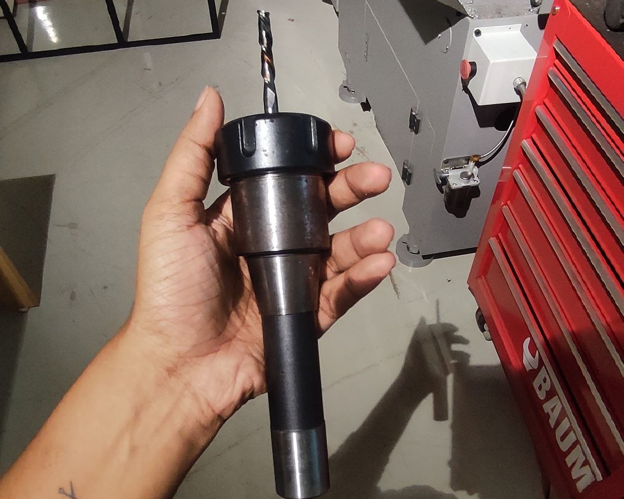
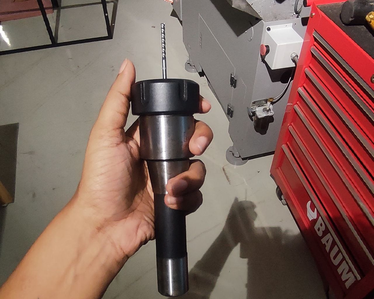
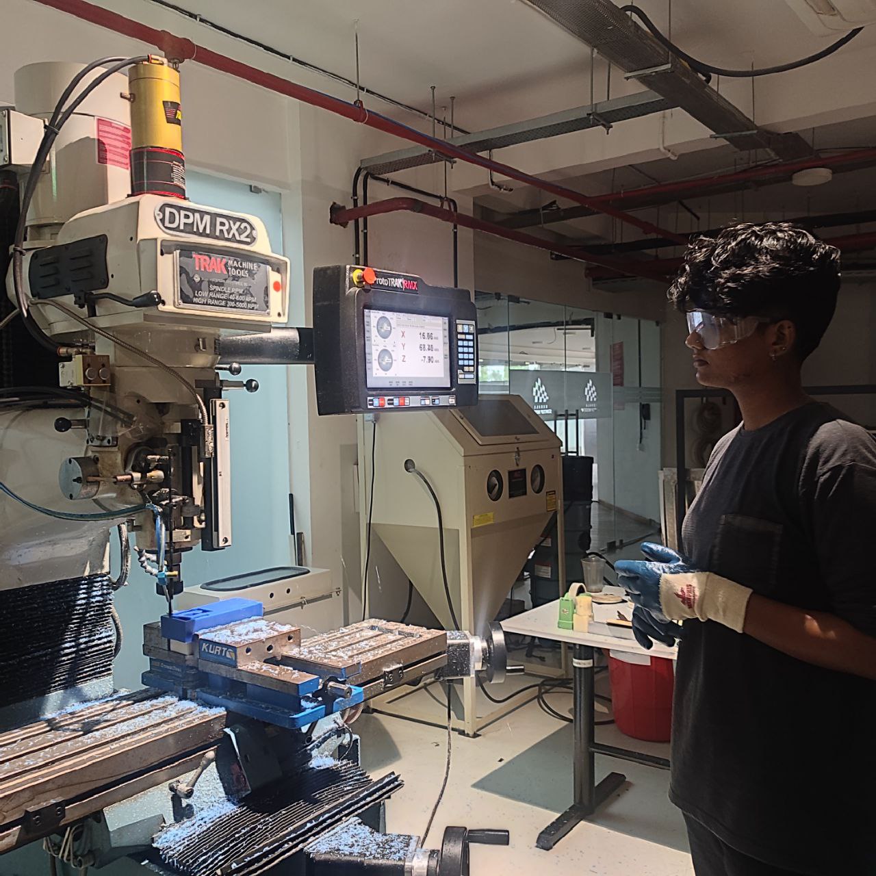
DPM RX2 Vertical Milling Machine
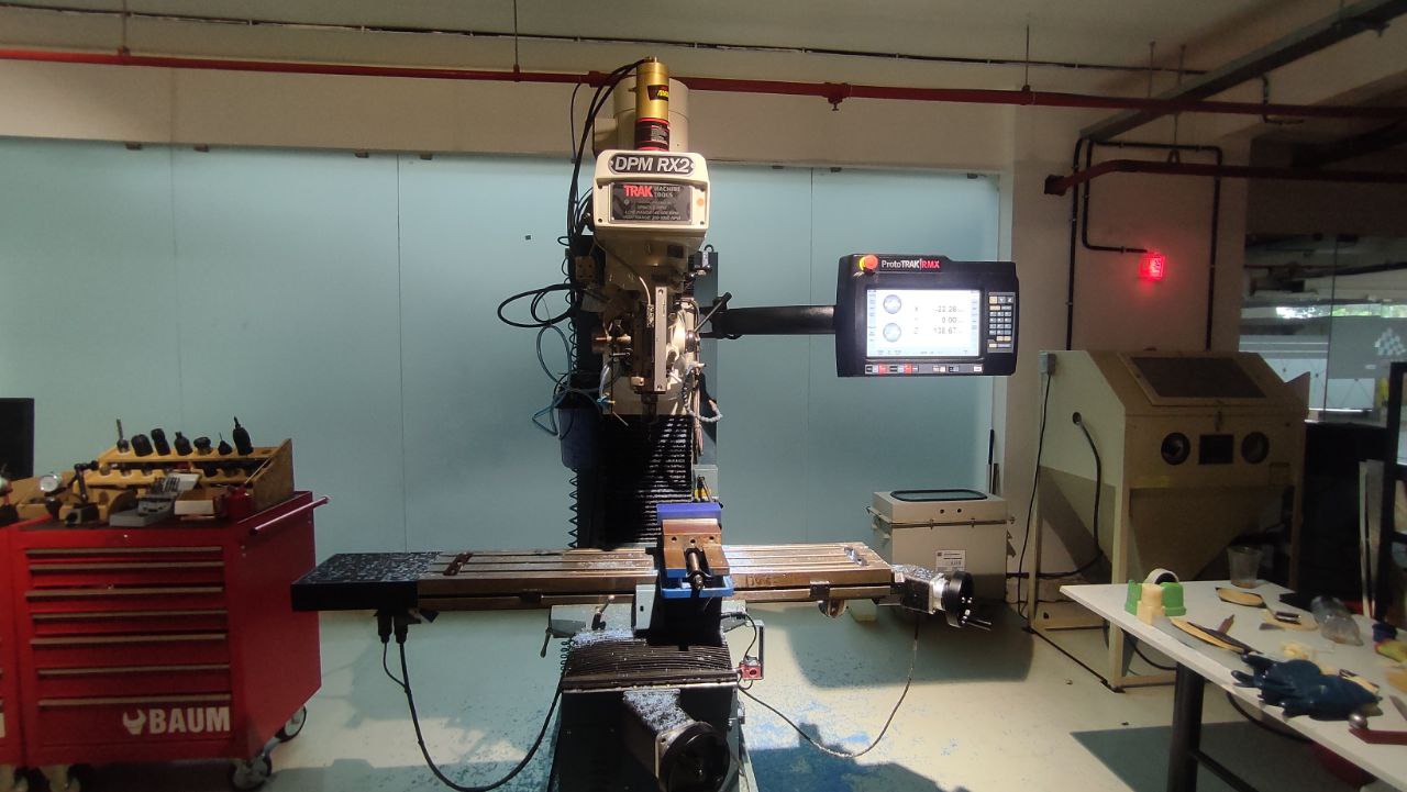
The vertical milling machine is a precise tool designed for shaping and fabricating by removing stock, usually from metal workpieces. These operations create a flat surface or specific spot on a workpiece, often with a particular orientation relative to other features, surfaces, or another piece.
• Table Size: 1240 x 230 mm
• Motor Type: 3 HP Continuous Spindle Motor
• Axis travel: 800 x 400 x 650 mm
• Spindle Taper: R8
• Head Swivel: +/- 90 degrees
• Quill Diameter: 33/8 inch
• Maximum Quill Travel: 5 inch
• Applications: Manual and CNC milling of metals
Setting up the Machine
The machine had so many operations that has to done before milling the piece. The first task is to set the origin. This process involves attaching the edge finder to the machine and setting the tool offset. Once the origin is established, the program can be loaded, and the tool offset adjusted for each specific tool used in the machining process. The tool offset is essential for ensuring precise machining with different tools.
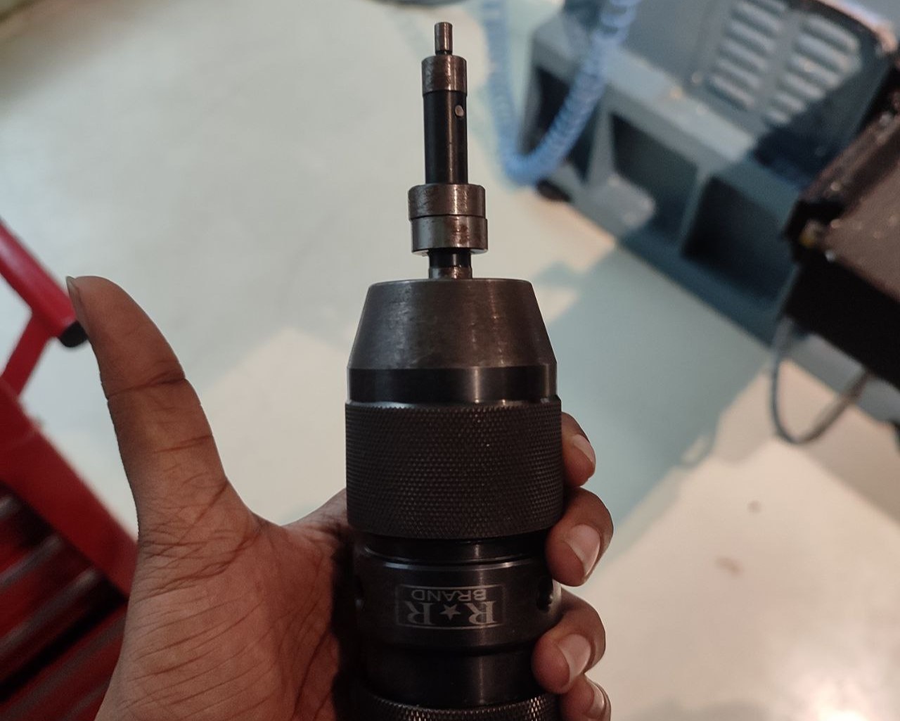
Edge Finder
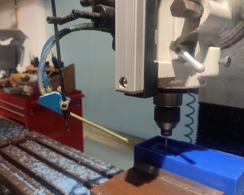
After securing the material, use the rotary encoders to adjust the X and Y axes. Alternatively, the machine interface along with an edge finder can be used to establish the X and Y coordinates, followed by setting the absolute X and Y axes. Then, adjust the Z axis by lowering the tool. Once all adjustments are made, set the reference Z axis by moving the tool downward again. Adding the tool reference ensures that the origin remains fixed during any tool changes.
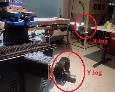
Turning the handles makes the X and Y axes jog.
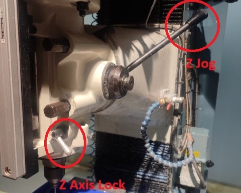
Turning the handles makes the z axis jog and the small lever locks the movement.
For Wax, coolant is not needed, so, only air is to be sprayed to remove the chips.
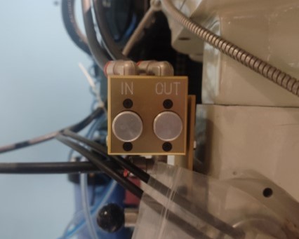
Press on the "Out" button to remove the tool module from the spindle and "In" to add new tool module.
Once the origin is set, next step is to upload the program. Click on "Prog In/Out" on screen and add the file. Next step is to add the tool details such as its diameter, number of flutes etc by clicking on "Tool Table".
Before running the codes directly, "traking" can be done to see if all the parameters given are right and if the work is done properly. Once satisfied, click on "CNC Run" for the machine to start milling.
Once the first operation is over, the tool had removes almost all the unecessary parts that can achieved by the 6mm bit. Next, 3mm flat end bit is inserted for the next two operations. Finally, 3mm ball nose bit is added for finishing.
Safety has to be ensured at each step. Wear gloves and goggles. Make sure not to wear loose clothes while working near the machine.
The machine provides an extra feature of giving a live visual representation of the toolpath during the process.
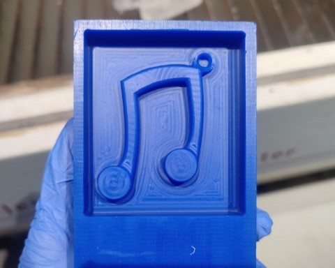
And finally, the milling was completed.
Molding
For creating the mold, we used Silicone Rubber RTV 1010.
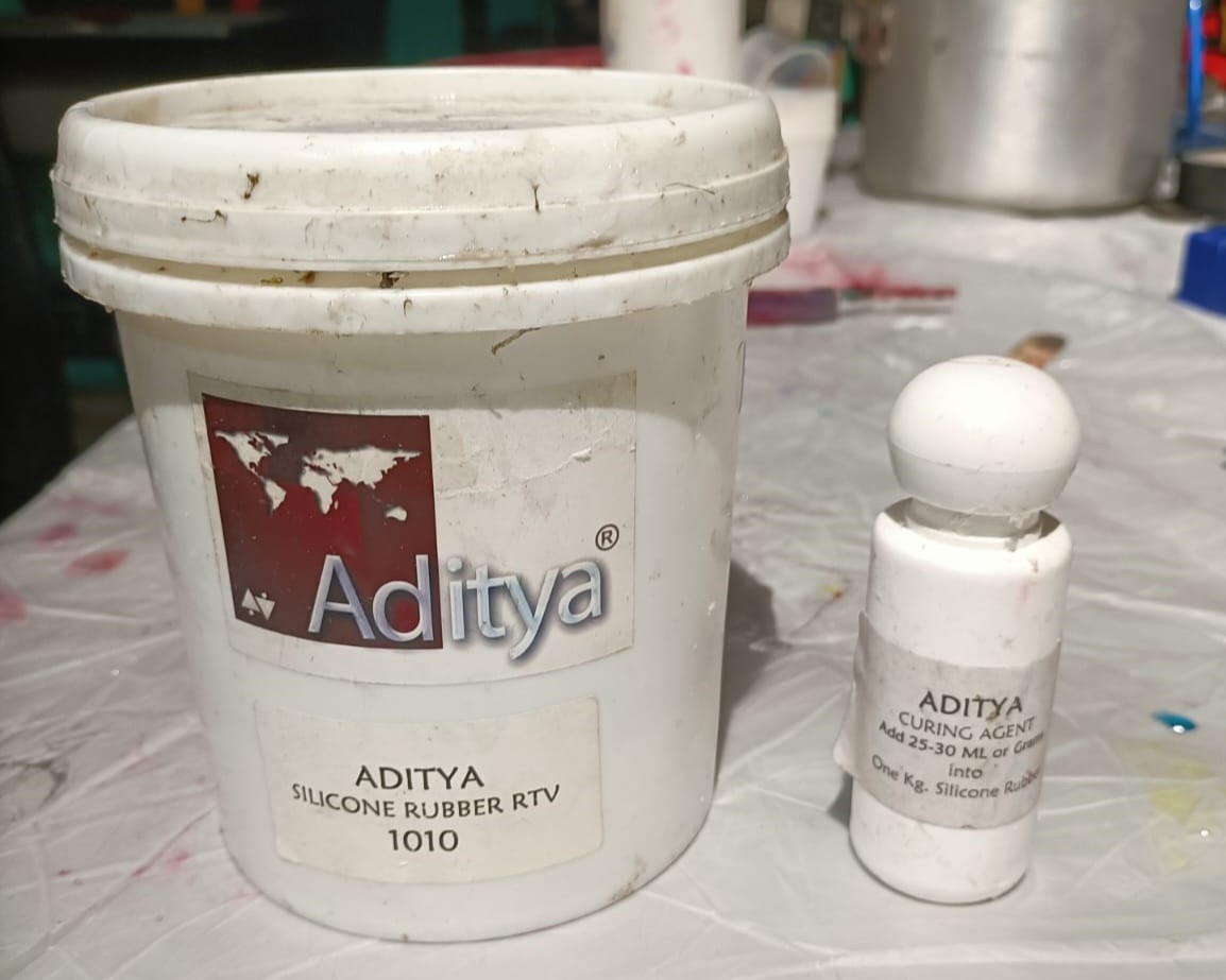
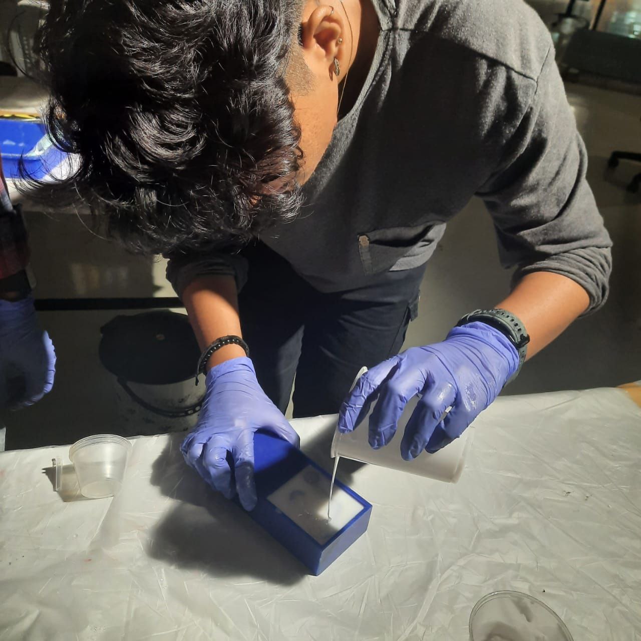
This is a dual-component silicone rubber designed for use in mold making and prototyping. It consists of a silicone rubber base and a curing agent that must be combined in a precise ratio to start the curing process. The ratio in which we added the curing agent was wrong in the first time and we had to do it again for it to harden. The ratio we finally used was for 1000ml, 30 ml of curing agent.
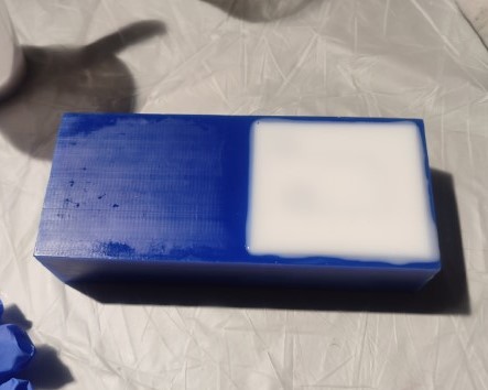
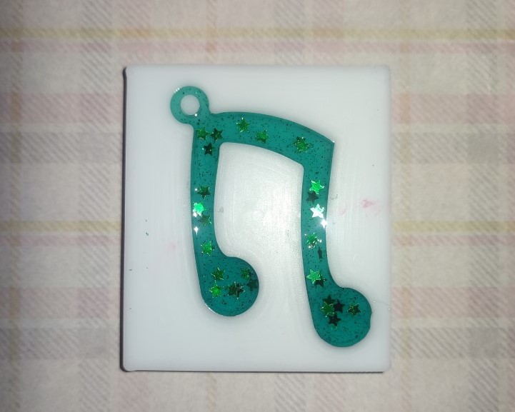
Next day once the mold had hardened, I removed the mold from the milled block using pressurized air.
Casting
The final step is to pour the resin and once it is cured, the final product will be ready. Here, we used Aditya Epoxy Resin 37.
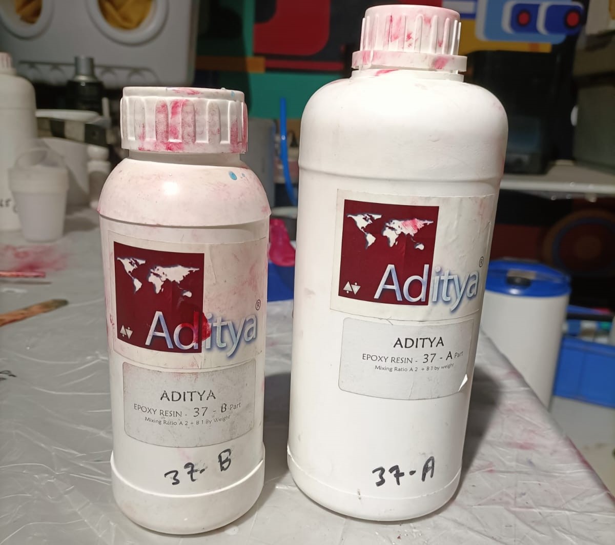
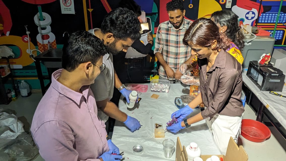
It has two components: A part and B part. It is to be added in the ration of 2:1. For mixing, all of us did the process together.
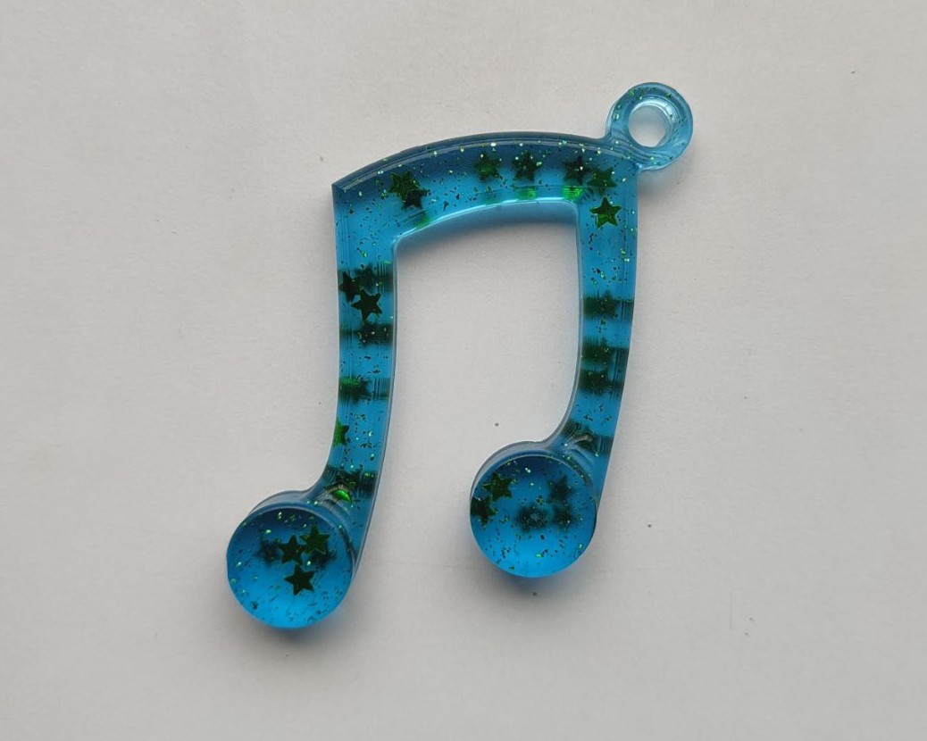
We used an in-house built vacuum chamber to remove the air from the resin after mixing so that there won't be any bubbles once it sets. Once done, all of us took the required amount. For my case, I wanted it to be green. So, I added a tiny bit of green dye and some glitter to make it look good to my satisfaction.
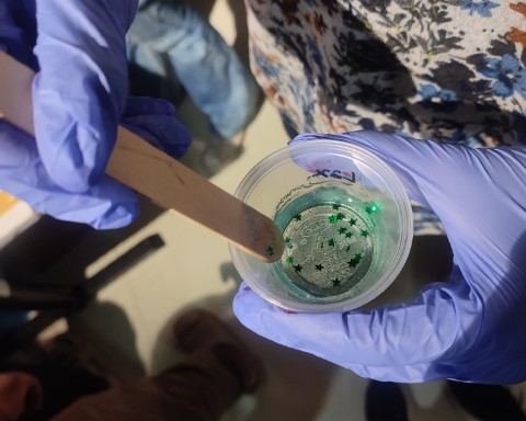
Once poured, I left it in a secured place for it to cure.
I took out the piece the next day. The resin needs atleast 72 hours to cure. So, when I took it out it was not rigid. So I kept it back. And here's the final result. I plan on making the piece again in different colours.
Download Files
• Design File