Input Devices
Objectives for Week 11
- Measure something: Add a sensor to the microcontroller board that you have designed and read it
- Group Assignment:
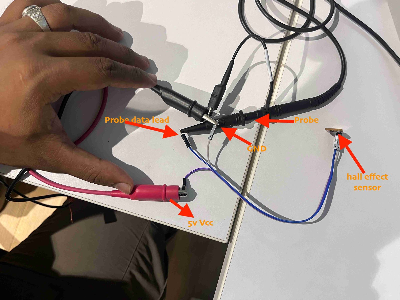
- Probe an input device's analog levels and digital signals
This week is about using an input device and I chose gyroscope as I will be using it for my final project. In my final project, I plan to create a die having gyroscope and bluetooth connectivity so that once the die is rolled, the corresponding number can be detected by the system for further process of moving the token.
MPU-6050
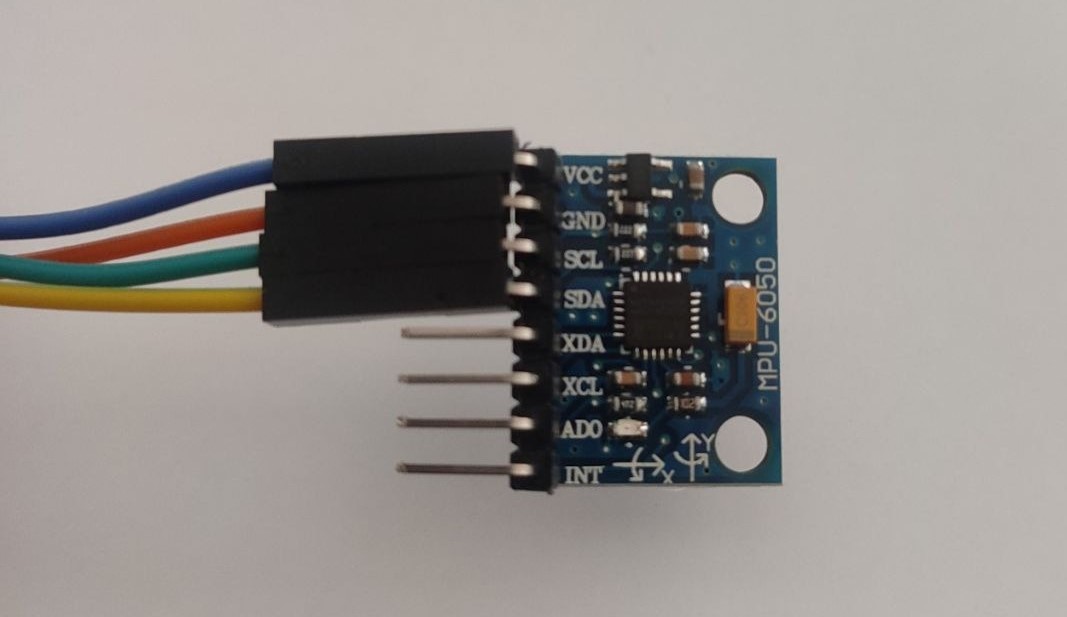
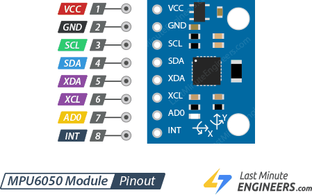
MPU-6050 sensor module is a combination of 3-axis accelerometer and 3-axis gyroscope. It is widely used for applications such as orientation detection, motion tracking and gesture detection.
Key Features
- 3-axis Gyroscope: Measures the angular rate aroung x,y, and z axes. This is useful for determining orientation and for stabilizing devices.
- 3-Axis Accelerometer: Measures linear acceleration in the x, y, and z directions. This helps in detecting motion as well as the orientation of the device relative to Earth's gravity.
- Temperature Sensor: Measures the temperature from the surrounding.
- Digital Motion Processor (DMP): An embedded processor that can perform complex computations on the sensor data, thus offloading the host processor. The DMP can be programmed to perform various motion sensing tasks like gesture recognition.
- I2C (Inter-Integrated Circuit) Interface: I2C is a serial communication protocol that enables multiple chips to communicate with each other over a short distance.
- Input Voltage: Typically operates at 3.3V or 5V, making it compatible with a wide range of development boards and systems.
The gyroscope in this module is a Micro-Electro Mechanical System (MEMS) and works on Coriolis effect. The MEMS sensor consists of a proof mass (consisting of four parts M1, M2, M3, and M4) that is maintained in a continuous oscillating movement so that it can respond to the coriolis effect. When the module is rotated, the coriolis force acting causes the vibration to change from horizontal to vertical. Depending on the axis along which the angular rotation applied, there are three modes: Roll, Pitch and Yaw.
sourced from Last Minute Engineers
The MEMS accelerometer is supported by polysilicon springs, enabling it to move in response to acceleration in the X, Y, or Z directions. When it moves, the capacitance between stationary plates and those connected to the movable structure alters. This variation in capacitance corresponds to the degree of acceleration experienced along a specific axis. The sensor detects these changes in capacitance and translates them into an analog voltage output.

sourced from Last Minute Engineers
To know more about MPU-6050 and the working principle of accelerometer and gyroscope, click on the link Last Minute Engineers
Microcontroller Board
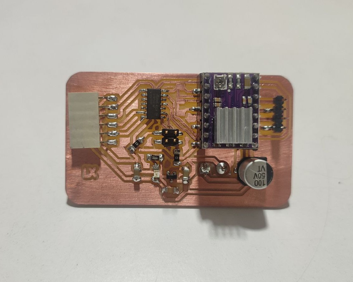
During 'Output Devices; week, I designed an ATtiny1614 microcontroller board to house the DRV8825 driver module for running a stepper motor. While doing the schematic, I took out the SDA, SCL, Power line(5V) and Ground using a 2x2pos Conn Header.
SDA and SCL are two important lines used in the I2C (Inter-Integrated Circuit) communication protocol, which is widely used for connecting low-speed devices in embedded systems. These two lines enable multiple devices (such as sensors, microcontrollers, displays, etc.) to communicate with each other over a simple, two-wire interface.
- SDA (Serial Data Line): This line is used for data transfer between devices. Data bits are sent one by one along this line, synchronized by the clock signal on the SCL line.
- SCL (Serial Clock Line): This line carries the clock signal provided by the master device. It is used to synchronize the data transmission over the SDA line between the master and the slave devices on the bus.
Refer Week 9 documentation for details on the microcontroller board that I had created.
Working with MPU-6050
Requirements:
- ATtiny1614 Microcontroller board
- MPU-6050 Module
- Jumper Wires
- Quentorres board (as Programmer)
- FTDI to UPDI Convertor
- Type-C Cable
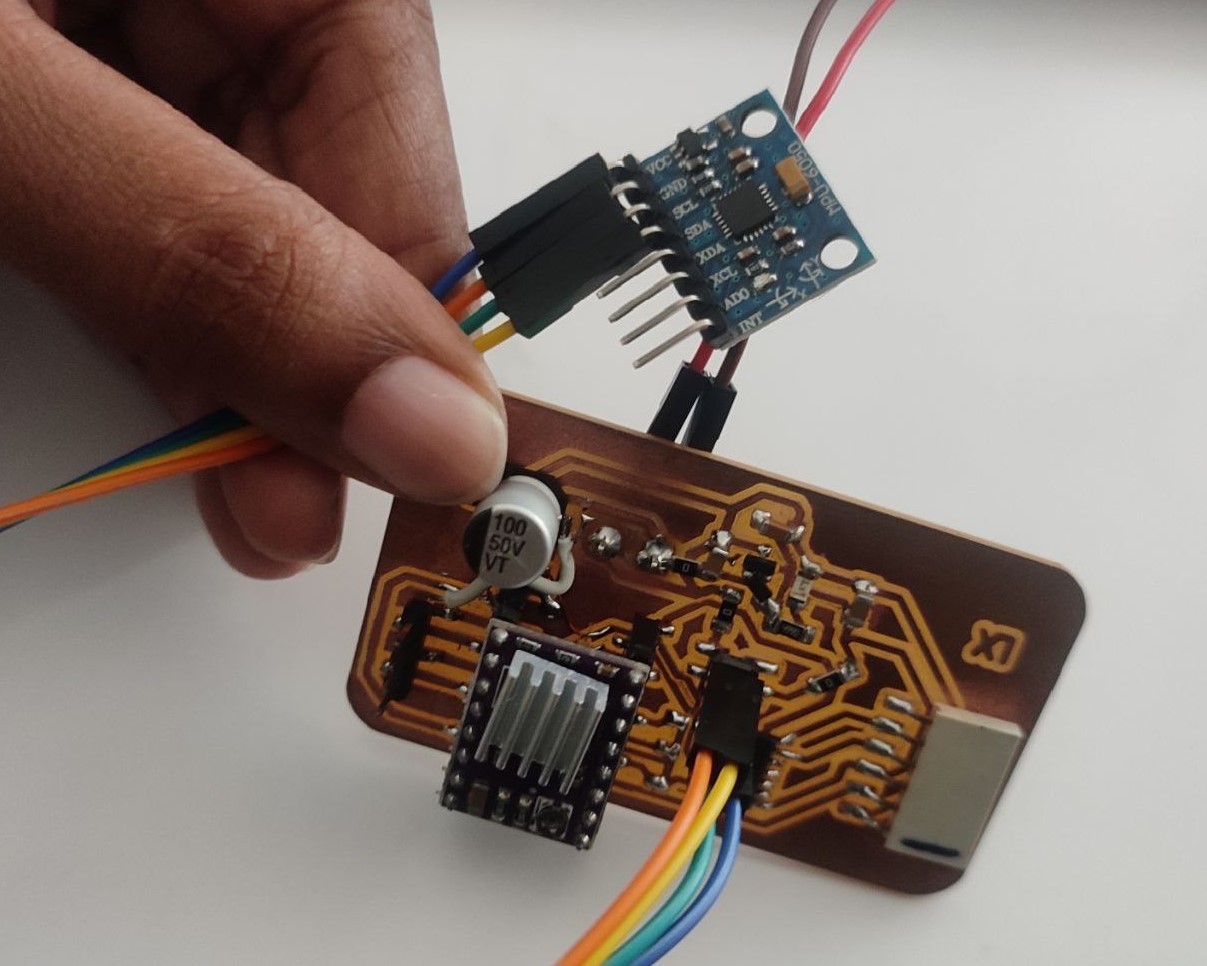
Connections:
- Connect the VCC pin of the MPU-6050 to a 5V output on the ATtiny1614.
- Connect the GND pin of the MPU-6050 to a ground pin on the ATtiny1614.
- Connect the SCL (Serial Clock) pin of the MPU-6050 to SCL pin on the ATtiny1614.
- Connect the SDA (Serial Data) pin of the MPU-6050 to SDA pin on the ATtiny1614.
- Connect the FTDI to UPDI convertor across the Quentorres and ATtiny1614 microcontroller board.
- Using Type-C, connect Quentorres to the system.
For Programming:
I'm using Arduino IDE for programming. Since, ATtiny board cannot be directly connected, I am using the Quentorres board I have made in Electronics Production week as the Programmer. Refer Week 9 to know how to burn bootloader and how to use Quentorres board as programmer and also to know the parameters set to use ATtiny1614 board.
For the MPU6050 module, I installed "MPU6050_light" library from the Library Manager in Arduino IDE.
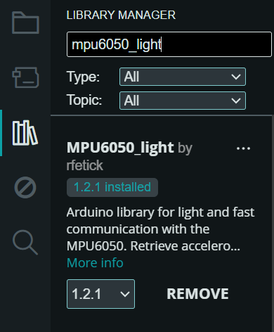
I took an example code from the library I installed.
.png)
Here's the code:
    /* Get all possible data from MPU6050
 * Accelerometer values are given as multiple of the gravity [1g = 9.81 m/s²]
 * Gyro values are given in deg/s
 * Angles are given in degrees
 * Note that X and Y are tilt angles and not pitch/roll.
 *
 * License: MIT
 */

#include "Wire.h"
#include

MPU6050 mpu(Wire);

long timer = 0;

void setup() {
  Serial.begin(115200);
  Wire.begin();

  byte status = mpu.begin();
  Serial.print(F("MPU6050 status: "));
  Serial.println(status);
  while(status!=0){ } // stop everything if could not connect to MPU6050

  Serial.println(F("Calculating offsets, do not move MPU6050"));
  delay(1000);
  mpu.calcOffsets(true,true); // gyro and accelero
  Serial.println("Done!\n");

}

void loop() {
  mpu.update();

  if(millis() - timer > 1000){ // print data every second
    Serial.print(F("TEMPERATURE: "));Serial.println(mpu.getTemp());
    Serial.print(F("ACCELERO  X: "));Serial.print(mpu.getAccX());
    Serial.print("\tY: ");Serial.print(mpu.getAccY());
    Serial.print("\tZ: ");Serial.println(mpu.getAccZ());

    Serial.print(F("GYRO      X: "));Serial.print(mpu.getGyroX());
    Serial.print("\tY: ");Serial.print(mpu.getGyroY());
    Serial.print("\tZ: ");Serial.println(mpu.getGyroZ());

    Serial.print(F("ACC ANGLE X: "));Serial.print(mpu.getAccAngleX());
    Serial.print("\tY: ");Serial.println(mpu.getAccAngleY());

    Serial.print(F("ANGLE     X: "));Serial.print(mpu.getAngleX());
    Serial.print("\tY: ");Serial.print(mpu.getAngleY());
    Serial.print("\tZ: ");Serial.println(mpu.getAngleZ());
    Serial.println(F("=====================================================\n"));
    timer = millis();
  }

}
While running the code, I faced a problem. The connection was irregular and I started receiving data only after couple of tries of removing and connecting the module. I'm not able to understand the root cause of this issue. Even when the module starts giving data, the data is improper. Therefore, I thought of using another module,i.e., Seeed Studio XIAO nRF52840 Sense.
Seeed Studio XIAO nRF52840 Sense
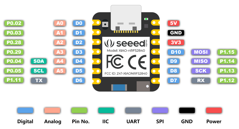
The Seeed Studio XIAO nRF52840 Sense is a compact development board equipped with a powerful Nordic nRF52840 MCU which integrates Bluetooth 5.0 connectivity. It is integrated with two extra onboard sensors. One of them is a Pulse Density Modulation (PDM) Digital Microphone. It can receive audio data in real-time which allows it to be used for audio recognition. The other one is a 6-axis Inertial Measurement Unit (IMU), this IMU can be very useful in TinyML projects like gesture recognition.
The first thing to note is that the Near Field Communication (NFC) interface is functional on the board. Secondly, there is a tiny reset button on the side of the Type-C interface. On the other side, there is a 3-in-one LED (User LED) along with a Charge LED to indicate the charging status when a battery is connected. There are 11 digital I/O that can be used as PWM pins and 6 analog I/O that can be used as ADC pins. It supports all three common serial interfaces such as UART, I2C, and SPI.
Working with XIAO nRF52840 Sense
I referred seeed studio tutorial on Getting Started with Seeed Studio XIAO nRF52840 (Sense).
Navigate to File > Preferences and paste the link https://files.seeedstudio.com/arduino/package_seeeduino_boards_index.json in Additional Boards Manager URLs.
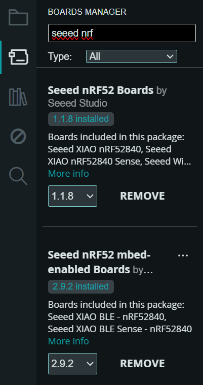
Next, I installed the boards from Boards Manager. It is recommanded to use the Seeed nRF52 Boards library if you want to apply Bluetooth function and "Low Energy Cost Function". It is recommanded to use the Seeed nRF52 mbed-enabled Boards library if you want to use it in embedded Machine Learning Applications or apply "IMU & PDM advanced function". Both libraries support very well when it comes to the basic usage, such as LED, Digital, Analog, Serial, I2C, SPI.
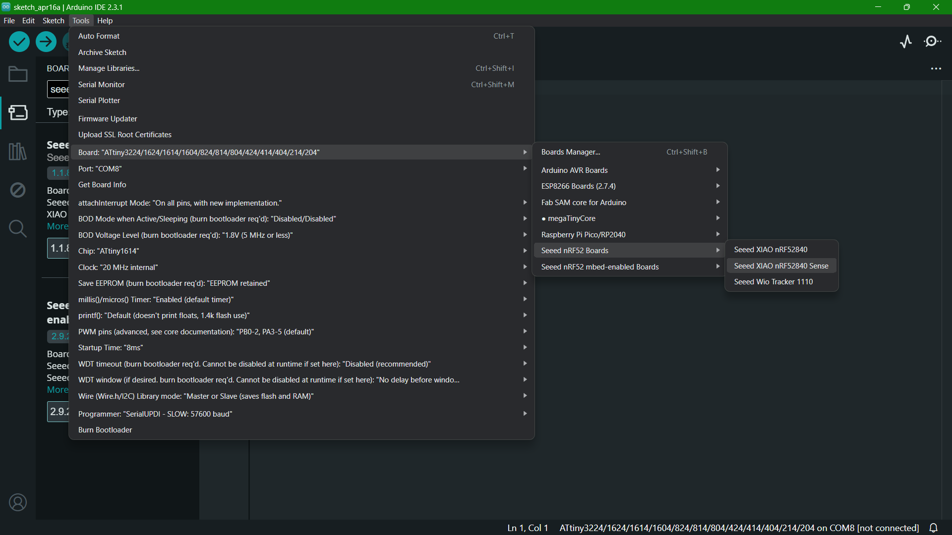
I selected the board and port as shown.
I uploaded the example Blink code from Arduino to see if the module is working.
It was working fine.
Next step is to check the gyroscope and temperature data of the module. For that I followed seeed studio tutorial on The 6-Axis IMU Usage on Seeed Studio XIAO nRF52840 Sense.
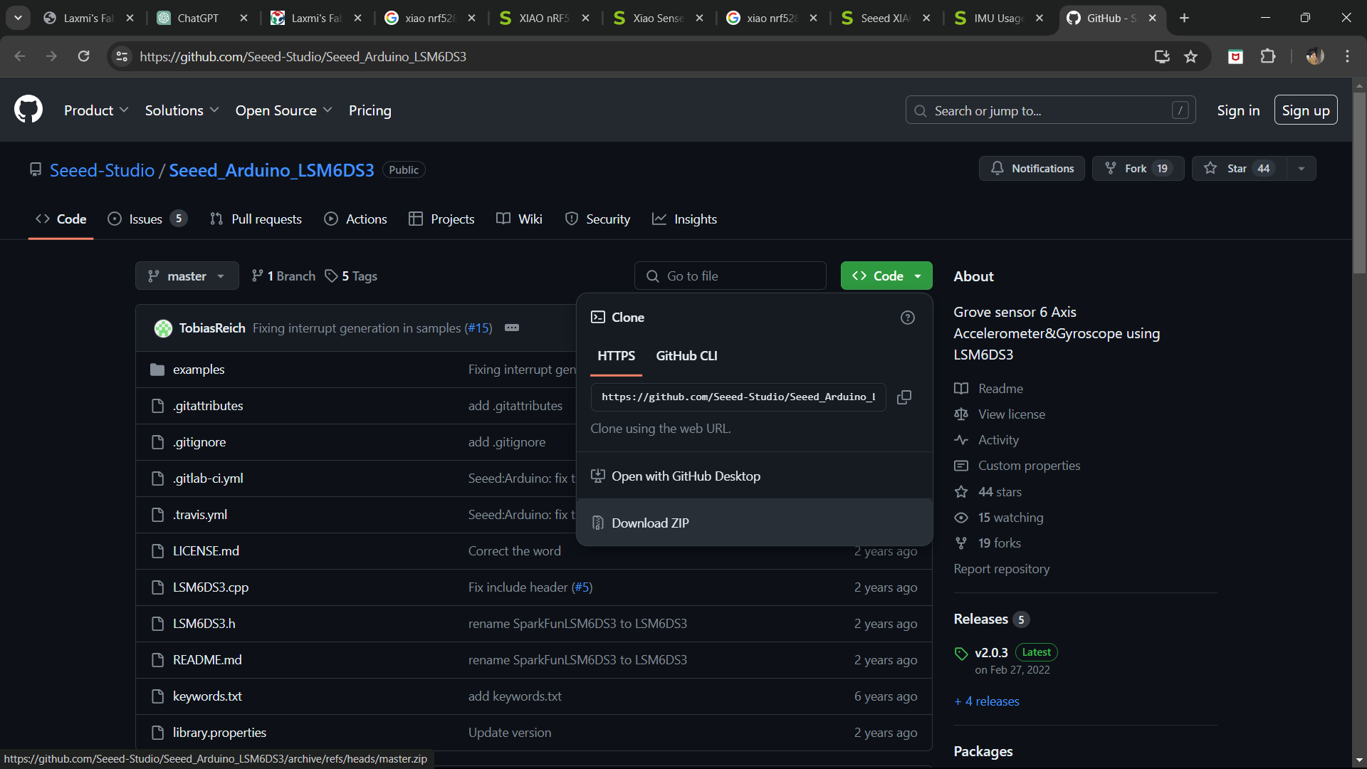
I followed the tutorial on adding a new library.
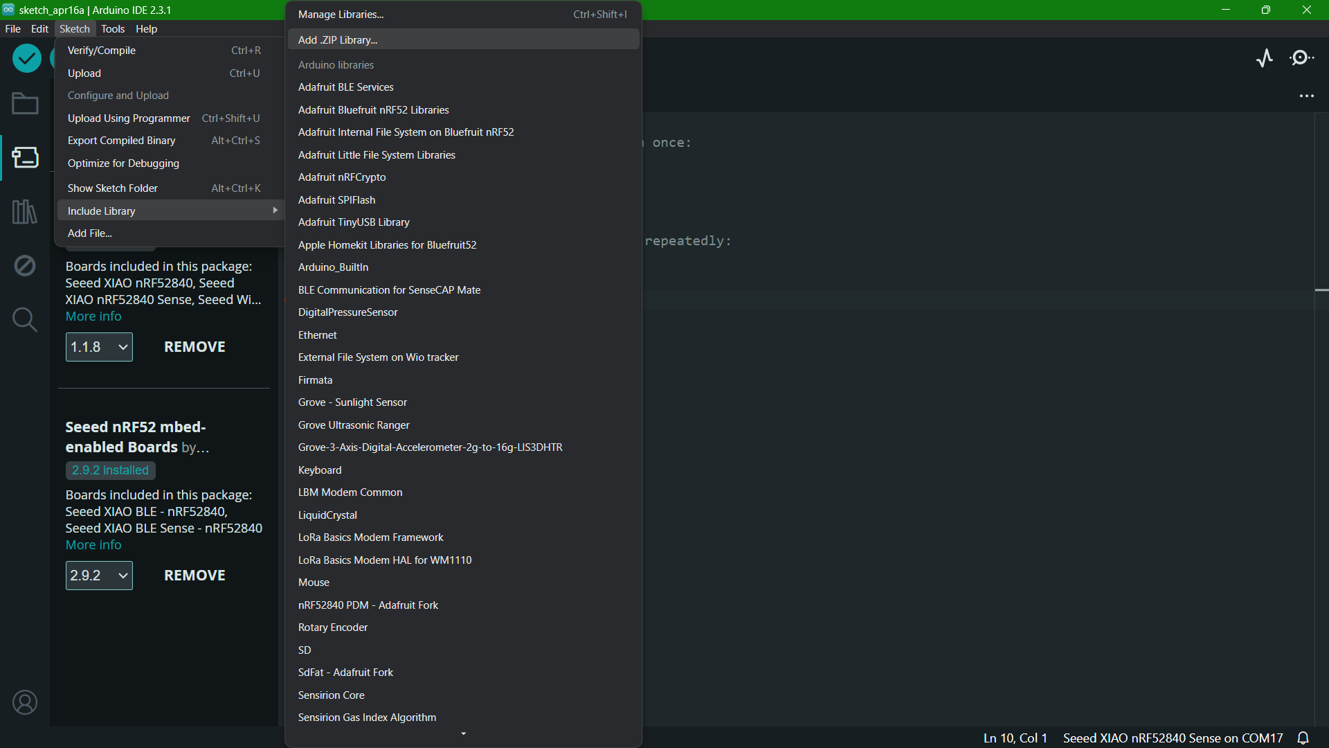
For example code, navigate to File > Examples > Seeed Arduino LSM6DS3 > HighLevelExample to open the HighLevelExample.
.png)
        /*****************************************************************************/
//  HighLevelExample.ino
//  Hardware:      Grove - 6-Axis Accelerometer&Gyroscope
//	Arduino IDE:   Arduino-1.65
//	Author:	       Lambor
//	Date: 	       Oct,2015
//	Version:       v1.0
//
//  Modified by:
//  Data:
//  Description:
//
//	by www.seeedstudio.com
//
//  This library is free software; you can redistribute it and/or
//  modify it under the terms of the GNU Lesser General Public
//  License as published by the Free Software Foundation; either
//  version 2.1 of the License, or (at your option) any later version.
//
//  This library is distributed in the hope that it will be useful,
//  but WITHOUT ANY WARRANTY; without even the implied warranty of
//  MERCHANTABILITY or FITNESS FOR A PARTICULAR PURPOSE.  See the GNU
//  Lesser General Public License for more details.
//
//  You should have received a copy of the GNU Lesser General Public
//  License along with this library; if not, write to the Free Software
//  Foundation, Inc., 51 Franklin St, Fifth Floor, Boston, MA  02110-1301  USA
//
/*******************************************************************************/

#include "LSM6DS3.h"
#include "Wire.h"

//Create a instance of class LSM6DS3
LSM6DS3 myIMU(I2C_MODE, 0x6A);  //I2C device address 0x6A

void setup() {
  // put your setup code here, to run once:
  Serial.begin(9600);
  while (!Serial)
    ;
  //Call .begin() to configure the IMUs
  if (myIMU.begin() != 0) {
    Serial.println("Device error");
  } else {
    Serial.println("Device OK!");
  }
}

void loop() {
  //Accelerometer
  Serial.print("\nAccelerometer:\n");
  Serial.print(" X1 = ");
  Serial.println(myIMU.readFloatAccelX(), 4);
  Serial.print(" Y1 = ");
  Serial.println(myIMU.readFloatAccelY(), 4);
  Serial.print(" Z1 = ");
  Serial.println(myIMU.readFloatAccelZ(), 4);

  //Gyroscope
  Serial.print("\nGyroscope:\n");
  Serial.print(" X1 = ");
  Serial.println(myIMU.readFloatGyroX(), 4);
  Serial.print(" Y1 = ");
  Serial.println(myIMU.readFloatGyroY(), 4);
  Serial.print(" Z1 = ");
  Serial.println(myIMU.readFloatGyroZ(), 4);

  //Thermometer
  Serial.print("\nThermometer:\n");
  Serial.print(" Degrees C1 = ");
  Serial.println(myIMU.readTempC(), 4);
  Serial.print(" Degrees F1 = ");
  Serial.println(myIMU.readTempF(), 4);

  delay(1000);
}
Dice Orientation
For my final project, I have to determine each orientation of the dice. For that, I need a code. I was not able to find any sample code for the same and also the codes given by ChatGPT wasn't satisfactory. My instructor, Saheen, shared an exercise code for a mouse click here. I modified the code to match my requirements. First I gave some random ranges and after testing I added the proper range of values.
#include "LSM6DS3.h"
#include "Wire.h"

//Create an instance of class LSM6DS3
LSM6DS3 myIMU(I2C_MODE, 0x6A);  //I2C device address 0x6A

void setup() {
  // Initialize serial communication at 9600 baud rate
  Serial.begin(9600);
  // Call .begin() to configure the IMU
  if (myIMU.begin() != 0) {
    Serial.println("Device error");
  } else {
    Serial.println("Device OK!");
  }
}

float vector_2_degrees(float x, float y) {
  float angle = atan2(y, x) * 180.0f / PI;

  if (angle < 0) {
    angle += 360;
  }

  return angle;
}

void loop() {
  // Accelerometer
  float x = myIMU.readFloatAccelX();
  float y = myIMU.readFloatAccelY();
  float z = myIMU.readFloatAccelZ();

  float angle_xz = vector_2_degrees(x, z);
  float angle_yz = vector_2_degrees(y, z);

  // Determine orientation and print it
  String Face = Orientation(angle_xz, angle_yz);
  Serial.println("Orientation: " + Face);
  // Serial.print("angle_xz:");
  // Serial.print(angle_xz);
  // Serial.print(",");
  // Serial.print("angle_yz:");
  // Serial.println(angle_yz);

  delay(1000);
}

String Orientation(float xz, float yz) {
  if ((80 < xz && xz < 100) && (80 < yz && yz < 100)) return "Top";
  if ((240 < xz && xz < 290) && (240 < yz && yz < 290)) return "Bottom";
  if (((60 < xz && xz < 110) || (240 < xz && xz < 360)) && ((340 < yz && yz < 360) || (0 < yz && yz < 12))) return "Right";
  if ((60 < xz && xz < 100) && (160 < yz && yz < 190)) return "Left";
  if (((340 < xz && xz < 360) || (0 < xz && xz < 12)) && ((170 < yz && yz < 190) || (240 < yz && yz < 360))) return "Front";
  if ((160 < xz && xz < 190) && (75 < yz && yz < 100)) return "Back";
  return "Unknown";
}
The results were pretty accurate and for my final project all I have to do is to change each orientation to its corresponding numbers on dice when rolled. That can be done once the dice is designed.
Group Assignment
This week's group assingment was to probe an input device's analog levels and digital signals. We chose Hall Effect sensor as the input device.
For further details, click on the link below.
Group Assignment-Week 11Download Files
• MPU6050 Arduino Code(zip)
• XIAO Arduino Code(zip)
• Dice Orientation Code (zip)