Computer-Controlled Machining
Objectives for Week 7
- Make (Design+Mill+Assemble) something big (meter-scale)
extra credit: don't use fasteners or glue and include curved surfaces
- Group Assignment: Do lab's safety training and Test runout, alignment, fixturing, speeds, feeds, materials and toolpaths for the machine
Group Assignment
This week's group assingment was to do the lab's safety training and to test the runout, alignment, fixturing, speeds, feeds, materials and toolpaths for the machine in our lab. We milled out a plywood test piece with various features mentioned in the group assignment.
For further details, click on the link below.
Group Assignment-Week 7Design
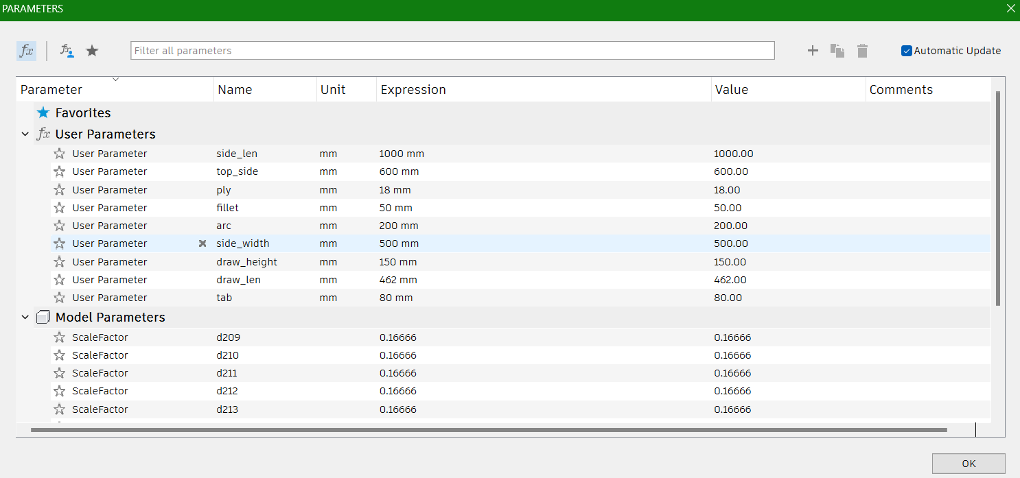
I decided to design a side table with a drawer for this week. I used Fusion 360 for designing. I defined some of the parameters as below such as plywood thickness, so that if any changes are to be made later, it won't affect the overall structure.
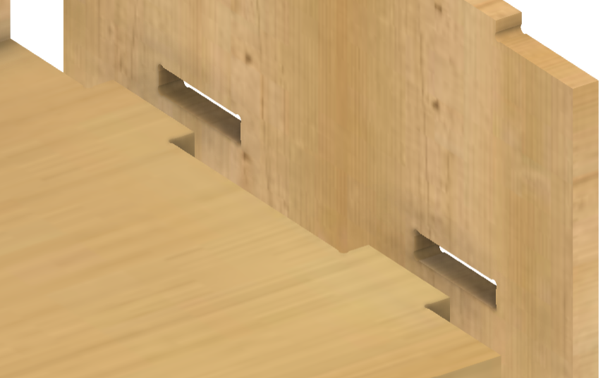
Overall, I gave slot joints to connect pieces of wood. It is also known as "slotted" or "keyed" joints. This method involves creating a slot or groove in one piece of wood and a corresponding tab or key in the other piece. The tab fits snugly into the slot, forming a tight and secure connection.
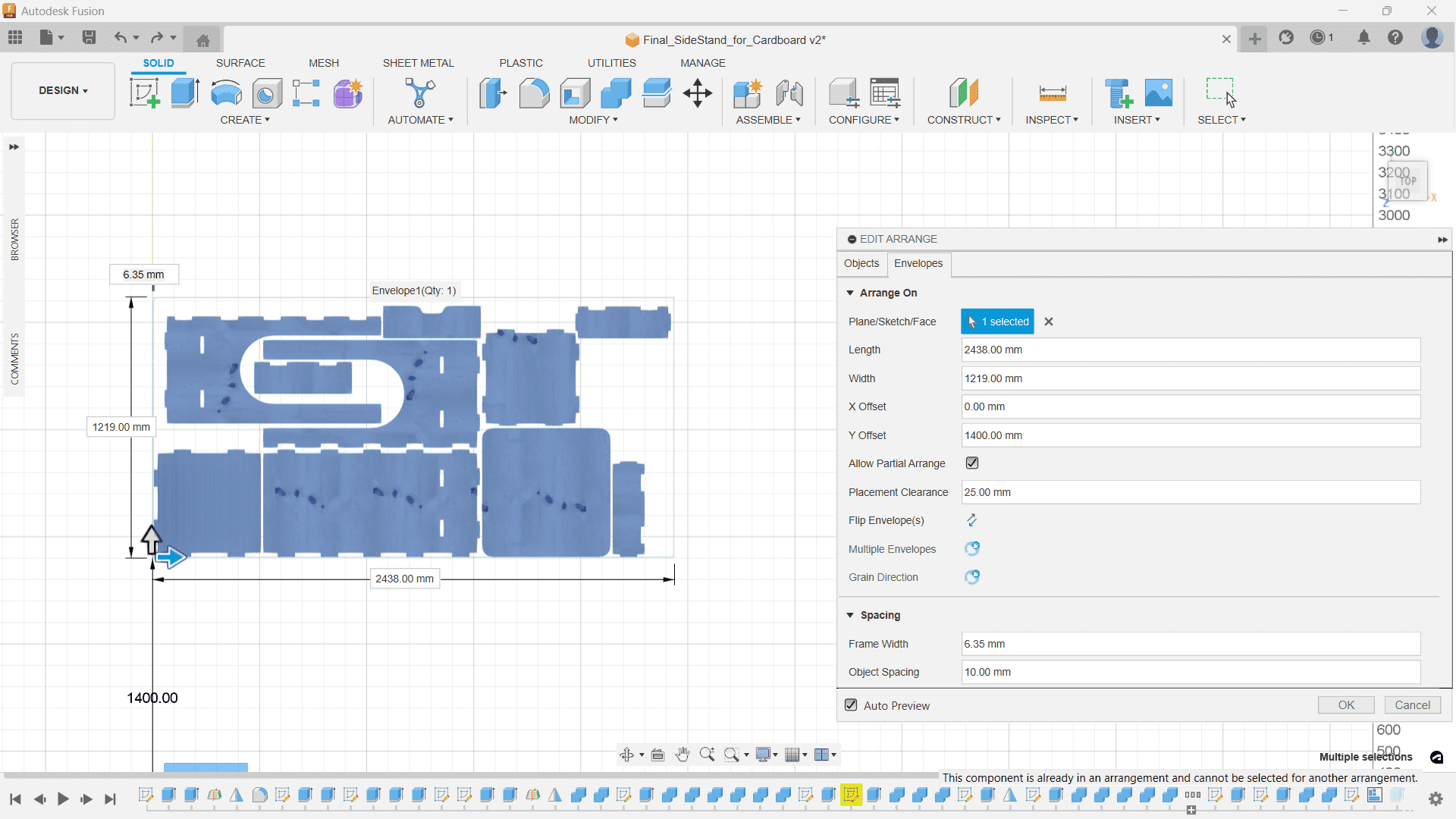
In our Fablab, we have 2 different thickness of plywood: 12mm and 18mm. I chose the 18mm plywood (8x4ft) for my work.
Using Arrange tool under Modify, I positioned the components to a 8x4ft plane.
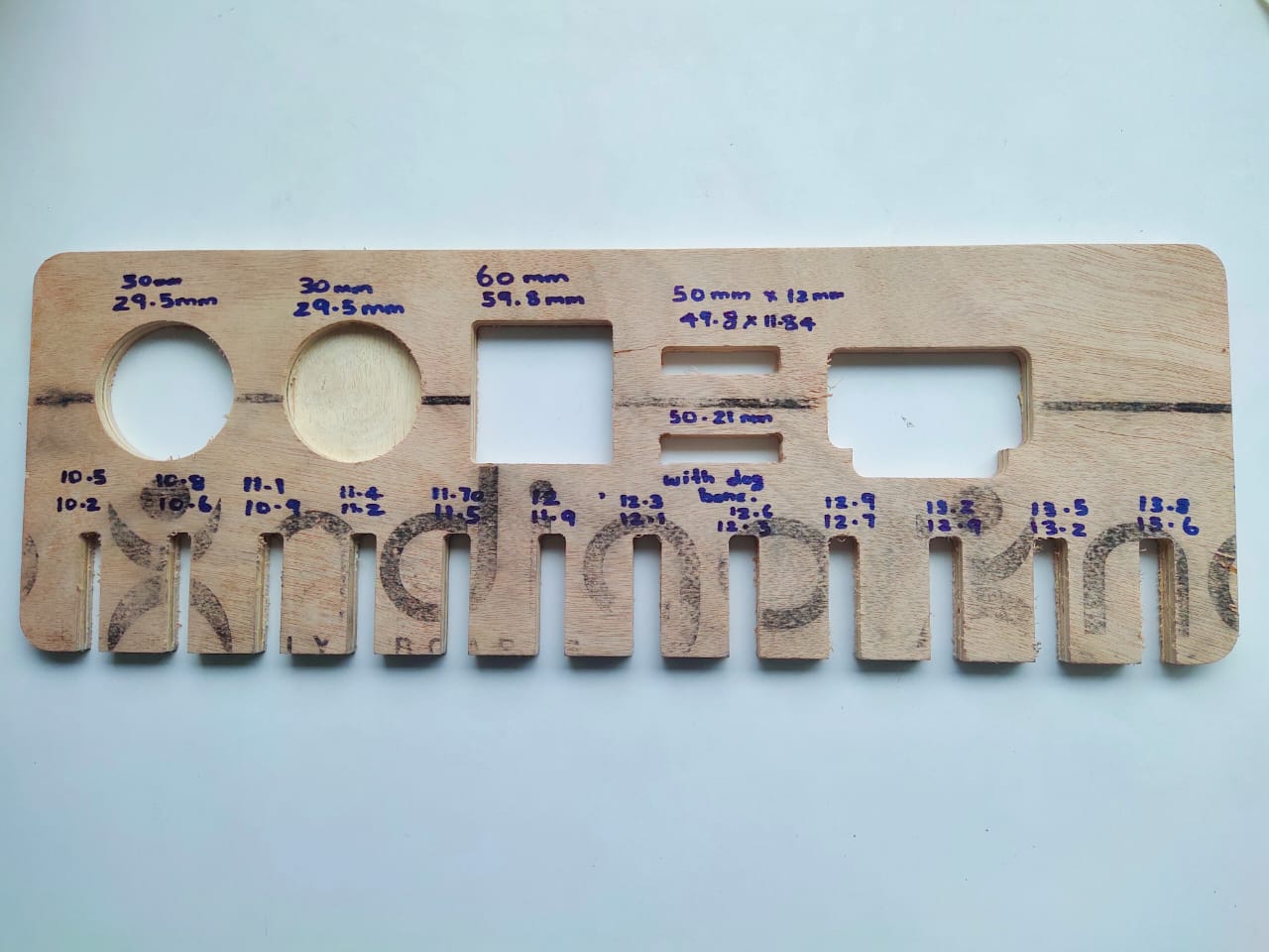
Before directly cutting the design on plywood, I first cut them in cardboard using Zund Digital Cutter. I am familiar with the Zund from Week 3 Assignment. So, for that I have scale down the arranged components so that the thickness would be changed from 18mm (ply thickness) to 3mm (cardboard thickness). I used a scale factor of 0.1667.
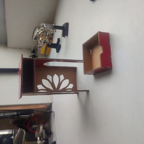
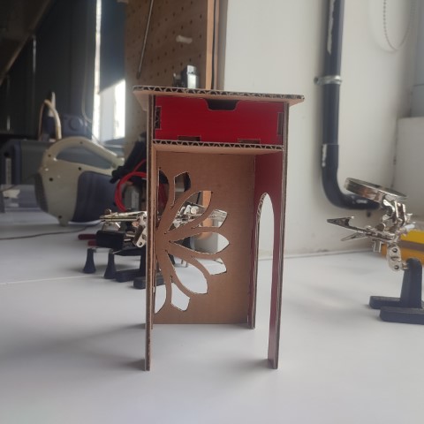
The cardboard models turned out to be good so I proceeded to prepare for the CNC Cutting.
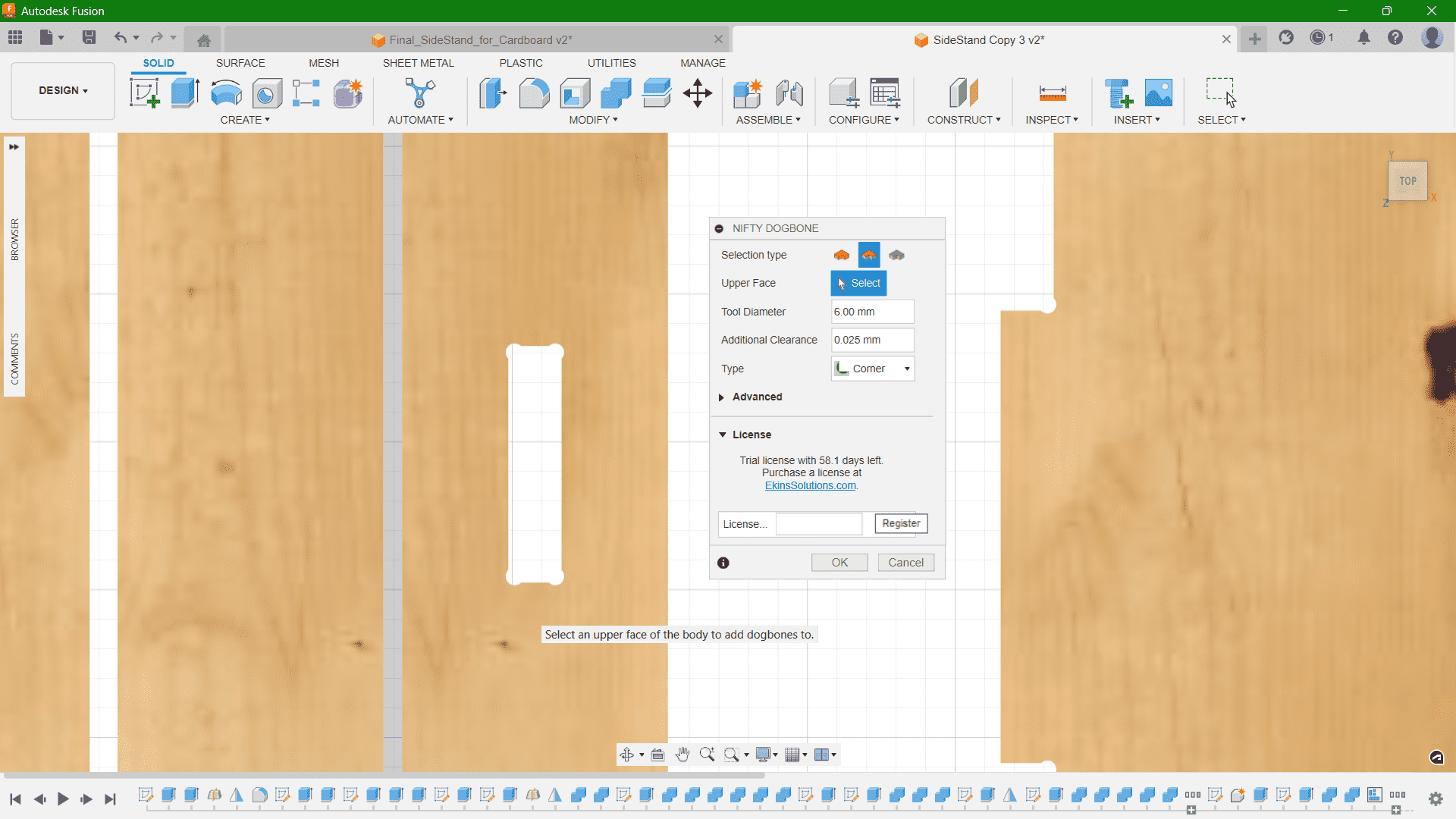
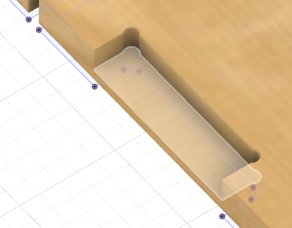
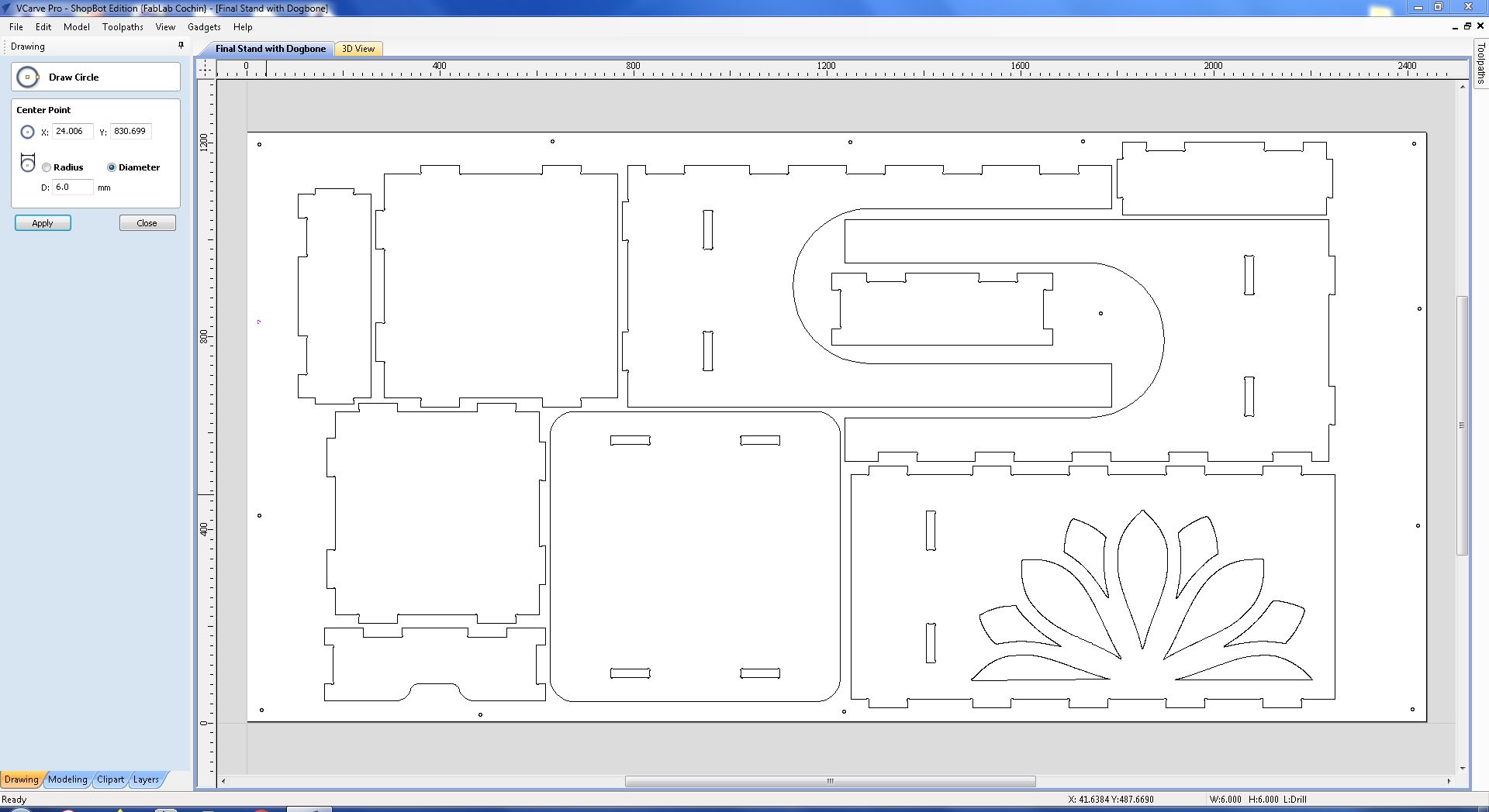
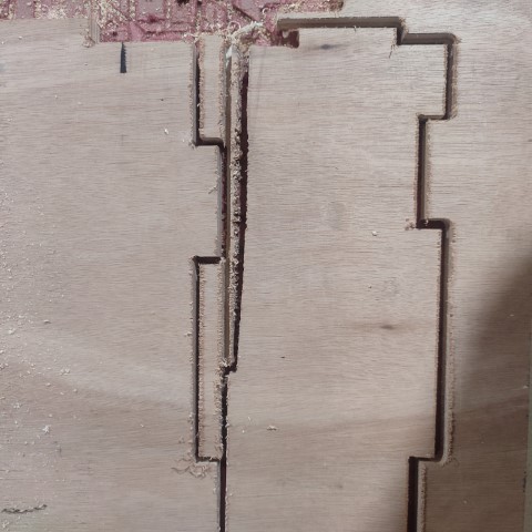
I provided Dogbones at all the slots I have given. It is a type of fillet added to the internal corners to get a complete clearance of the material by the milling cutter. End mills are round, so they cannot create perfect sharp internal corners. Without dogbones, the parts may not fit together properly due to the radius left by the tool. I downloaded the Fusion plugin Nifty Dogbone for this purpose.
Then, I projected the sketch face and saved the sketch in .dxf file format.
Note: I had provided pockets and side grooves to get good finish on the outside. It is important to close the sketch lines at the sides if it is for pockets and then project the pockets as a whole.
VCarve
The CAM for the toolpath can be done on Fusion itself. But as suggested by our instructor, Mufeed, we chose VCarve. VCarve is a CAM software for CNC milling and engraving. I imported my .dxf file in VCarve and gave the basic parameter values such as job size, origin, and material thickness. Before assigning the thickness value, I used vernier calliper to measure the thickness of the exact plywood I'll be using, and from the measurement it was clear that the thickness was varying between 17.6mm to 19mm. So I gave 19mm as the thickness in the software.
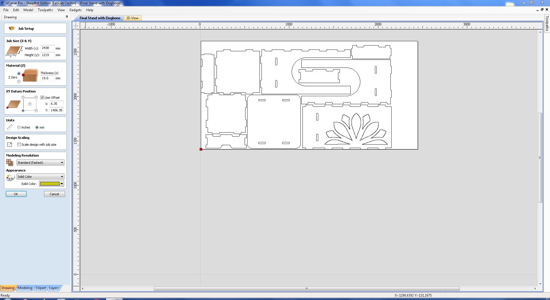
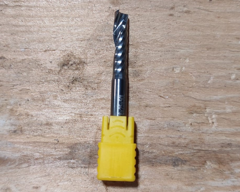
Mill Bit: Single flute 6mm End Mill
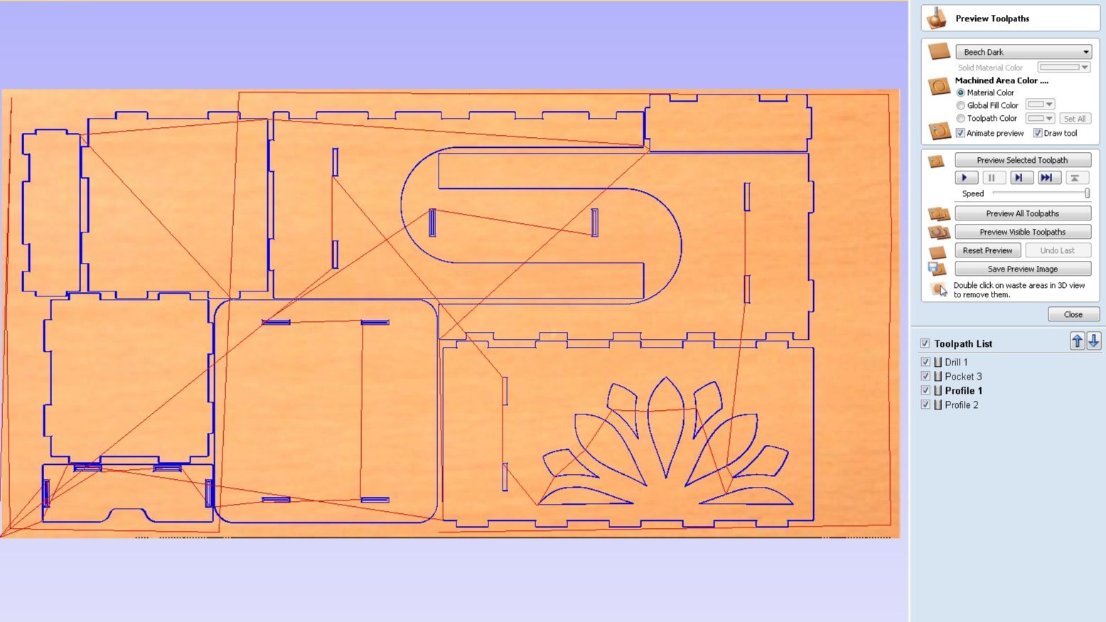
It is important to clamp the plywood before cutting so that it doesn't move while cutting. So we use screws on the edges and parts were the material will not be cutting. It is better to give a separate toolpath for the positions than calculating the positions manually. So I provided the toolpath positions for pre-drill where the screws will be used.
I divided the milling in 4 parts: Drill (Pre-drill), Pockets, Inner Cut, and Outer Cut.
ShopBot PRS Alpha 96 CNC Router
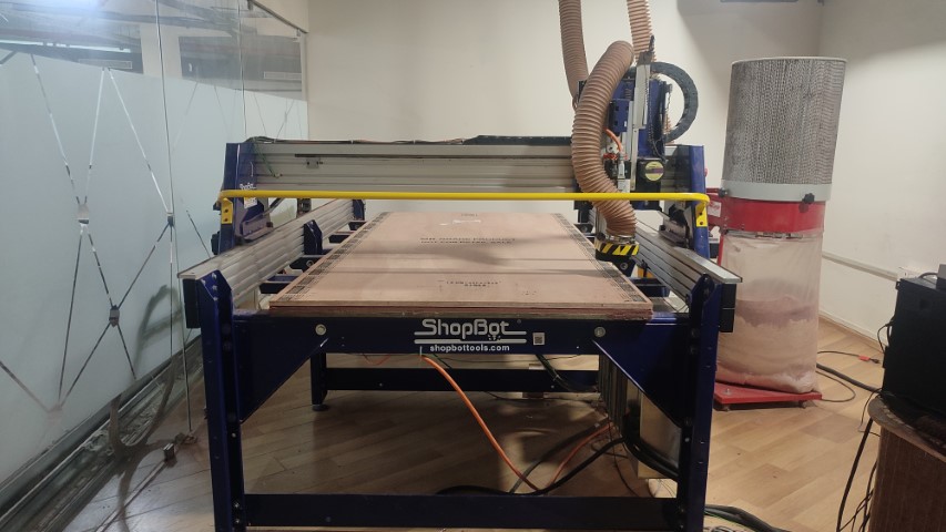
Features:
- Bed Size: 1.7526x2.438m
- Table Thickness: 3/4" Plywood Bottom Layer & MDF Top Layer
- Stationary Bed
- Tool Module moves in X,Y, and Z directions
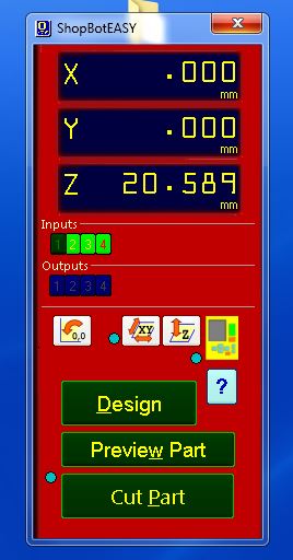
Once the toolpath files are ready, next step is to open the ShopBot's software ShopBot 3.
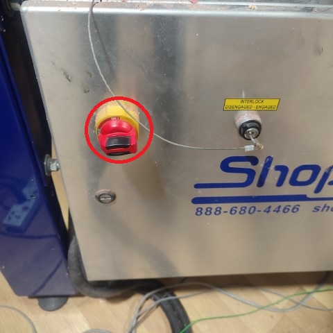
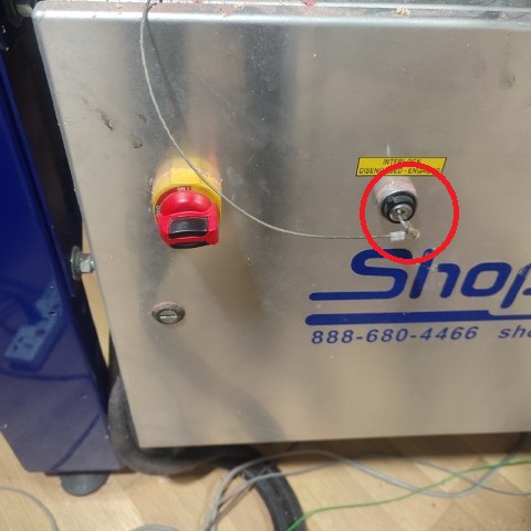
Switch on the ShopBot by turning the knob on the side panel of ShopBot.
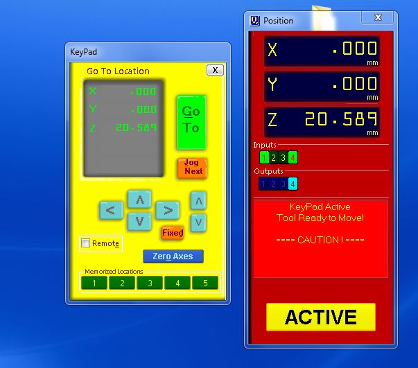
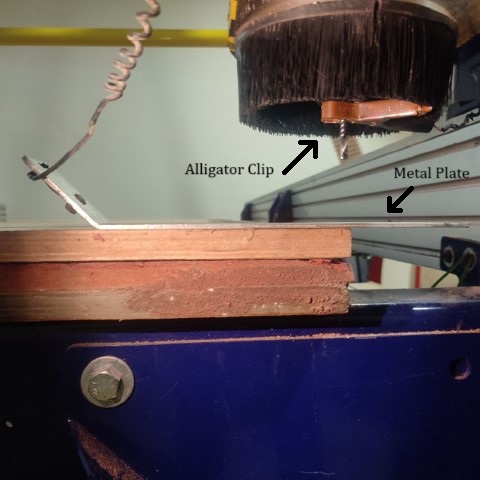
Next step is to set the origin . For that, the module can be jogged along the X and Y axis to set the zero position. For Z axis, the machine comes with a plate and an alligator clip. The machine detects the position when the clip and the metal plate comes in contact and then automatically sets the Z axis's zero position.
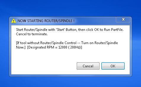
When all the three axes are zeroed, then click on Cut Part to upload the file. Click on Start and then a pop-up box appears requesting to switch on the spindle. For that, turn the key provided at the side panel of the machine once.
Now press Start button on the remote and once the spindle starts spinning, click OK on the dialogue box. Likewise, four of my files were uploaded and the design was milled.
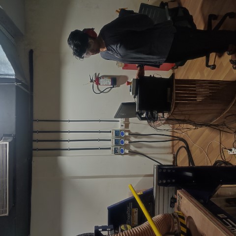
This is me standing right next to the remote ready to press the Emergency Button incase something goes wrong.
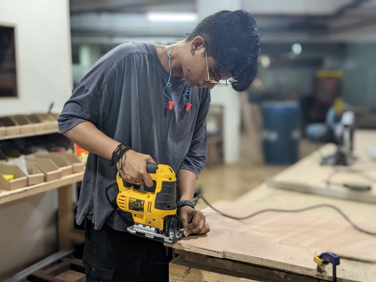
I had forgotten to put tabs on the design and it kind of ruined one of the piece. Thankfully it wasn't much so I used Jigsaw to cut a straight line out of it.
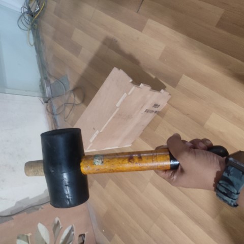
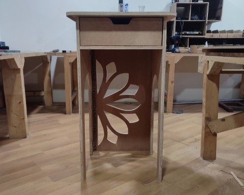
With the help of mallet and hammer and also utilizing the strength of my instructors, I joined the components and used a sander to sand the sides.
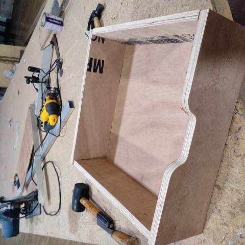
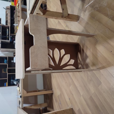
Here's the final outcome:
Download Files
• Side Stand for Cardboard (.dxf file)• Side Stand for CNC Machining (.dxf file)