Embedded Programming
Objectives for Week 6
- Write a program for the microcontroller developement board made in Week 4 to interact (with local input &/or output devices) and communicate (with remote wired or wireless devices)
extra credit: use different languages &/or development environments and also connect external components to the board
- Group Assignment: Browse through the data sheet for the microcontroller used and compare the performance and development workflows for other architectures
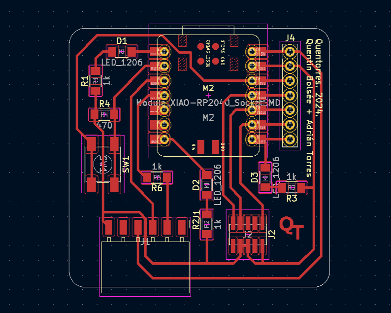
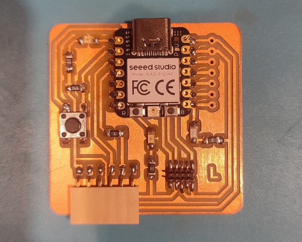
Quentorres Board
Quentorres board was created by Quentin Bolsée and redesigned by Adrián Torres in 2024 during Instructors Bootcamp in León. This versatile board is designed to program new AVR (Automatic Voltage Regulators) Series 1 and 2, as well as ARM (Advanced RISC Machines) microcontrollers. It includes a button and LEDs for basic input and output functionality, and features breakout pins for connecting additional external elements.
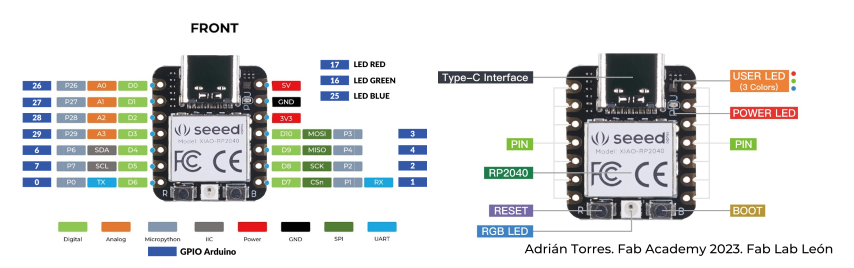
XIAO RP2040
The Seeed Studio XIAO RP2040 is a miniature development platform, energized by the RP2040 microcontroller, which boasts dual ARM Cortex-M0+ cores clocked at up to 133MHz, providing robust processing capabilities for embedded projects. It features onboard USB-C support for both programming and power supply, alongside a range of I/O options including digital, analog, PWM, UART, I2C, and SPI ports, ensuring flexible interfacing with various external peripherals. The board is Arduino-compatible, enabling users to easily program it using the Arduino IDE and benefit from its vast ecosystem and community support. Despite its compact footprint, the XIAO RP2040 offers expansion capabilities through its GPIO pins, making it an ideal choice for a wide array of embedded projects where space is at a premium. More information can be found here.
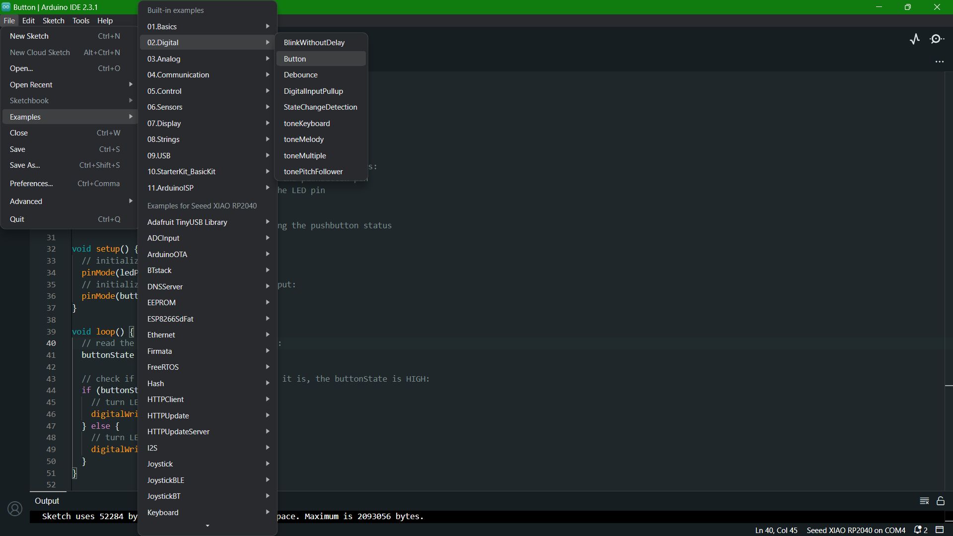
Coding in Arduino IDE
This week started with a session organized by our instructor, Saheen. The basics of coding was explained in detail with the help of examples available in Arduino IDE. We used the microcontroller development board we had created in Week 4 to run the codes.
In week 4, I tried blinking all the three LEDs with a delay of 0.5 seconds. During this week's class, we tried assigning functions to the button in Quentorres board. Also, Saheen suggested we write the algorithms for the code before programming to identify the proper logic and it was really helpful while creating code. I used the example code in Arduino to modify it to my requirement. I did the same program of switching an LED on and off in two ways: with boolean operation and without boolean operation.
Algorithm and Code to Switch ON and OFF an LED using Button (without Boolean)
• Algorithm
Step 1: StartStep 2: Define a variable 'V1' to read the status of button
Step 3: Define a variable 'V2' to read the status of LEDs
Step 4: Define LED as output and the button as input
Step 5: Let 'Status' read the value of 'button'
Step 6: If 'V1' is 'HIGH', and if 'V2' is 'LOW', LED ON, else LED OFF
Step 7: Go to Step 5
• Code
            const int buttonPin = 27;  // the number of the pushbutton pin located from Quentorres Data Sheet
            const int ledPin = 0;    // the number of the LED pin located from Quentorres Data Sheet

            int buttonState = 0;  // variable for reading the pushbutton status
            int LEDState=0; // variable for reading the LED status

            void setup() {
              // initialize the LED pin as an output:
              pinMode(ledPin, OUTPUT);
              // initialize the pushbutton pin as an input:
              pinMode(buttonPin, INPUT);
            }

            void loop() {
              // read the state of the pushbutton value:
              buttonState = digitalRead(buttonPin);
              if (buttonState==HIGH){
                // read the state of the LED value:
                 LEDState = digitalRead(ledPin);
                 if (LEDState==HIGH){
                  digitalWrite(ledPin,LOW);
                 } else {
                  digitalWrite(ledPin,HIGH);
                 }
              }
            }
Algorithm and Code to Switch ON and OFF an LED using Button (with Boolean)
• Algorithm
Step 1: Start
Step 2: Define values for button pin and LED pin.
Step 3: Define a boolean operation with variable 'flag' and assign the value 'false'
Step 4: Create a variable for reading the pushbutton status
Step 5: Initialize the button pin as input and LED pin as output
Step 6: Let the variable buttonState read the status of button
Step 7: If buttonState is high, value of 'flag' changes to opposite.
Step 8: Go to Step 6.
• Code
            const int buttonPin = 27;  // the number of the pushbutton pin located from Quentorres Data Sheet
            const int ledPin = 0;    // the number of the LED pin located from Quentorres Data Sheet
            bool flag=false; // boolean operation
            // variables will change:
            int buttonState = 0;  // variable for reading the pushbutton status

            void setup() {
              // initialize the LED pin as an output:
              pinMode(ledPin, OUTPUT);
              // initialize the pushbutton pin as an input:
              pinMode(buttonPin, INPUT);
            }

            void loop() {
              // read the state of the pushbutton value:
              buttonState = digitalRead(buttonPin);
            if (buttonState==HIGH){
              flag=!flag; //changes to opposite value
            }
            digitalWrite(ledPin, flag);

            }
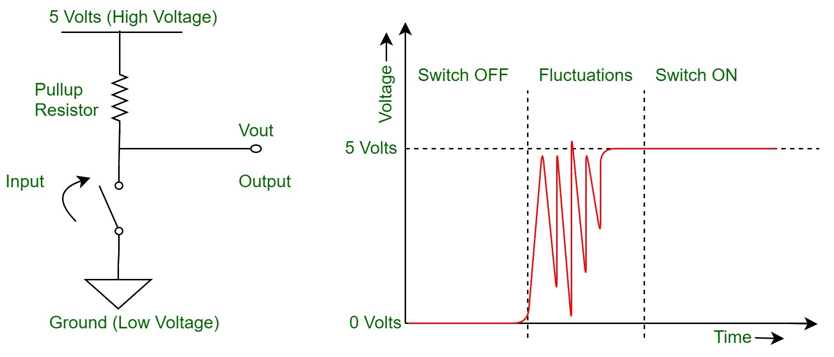
Bounce
The only problem I faced while testing both the codes is that if I pressed on the button slightly long, the result I obtained wasn't matching with the expected. Saheen mentioned that it is due to bouncing. When you press a button, it quickly touches another piece of metal, then stops, then touches it again several times. This happens very fast, about 10 to 100 times in just 1 millisecond. Because this happens so quickly, the electronic circuit can think you're pressing the button many times instead of just once. This is called Switch Bouncing. The following image illustrates a typical switch bounce, without any sort of bounce control.
In order to debounce, I tried giving a delay of 0.2s. It worked, but, then another issue arised. Pressing a button for long starts the LED to blink. For that, we tried defining a boolean operation 'pressed'. This operation let the circuit know that the button has been pressed, so that ON and OFF of the LED will go alternatively with each press and avoid bouncing.
Code to Switch ON/OFF an LED using Button (with delay and debouncing)
const int buttonPin = 27;  // the number of the pushbutton pin
const int ledPin = 0;    // the number of the LED pin

const int buttonPin = 27;  // the number of the pushbutton pin
const int ledPin = 0;    // the number of the LED pin
bool flag=false; // boolean operation
bool pressed=false;
// variables will change:
int buttonState = 0;  // variable for reading the pushbutton status

void setup() {
  // initialize the LED pin as an output:
  pinMode(ledPin, OUTPUT);
  // initialize the pushbutton pin as an input:
  pinMode(buttonPin, INPUT);
  delay(2000);
}

void loop() {
  // read the state of the pushbutton value:
  buttonState = digitalRead(buttonPin);
if (buttonState==HIGH){
  if (pressed==false){
      flag=!flag; //changes to opposite value
      pressed=true;
  }

}else{
  pressed=false;
  delay(50);
}
digitalWrite(ledPin, flag);

}
Serial Communication
Serial communication is a method used to send data one bit at a time, sequentially, over a communication channel or computer bus. This is in contrast to parallel communication, where multiple bits are sent simultaneously. Serial communication is commonly used for transmitting data between a microcontroller and peripherals or other computers.
Serial Monitor: The Serial Monitor in the Arduino IDE is a feature that allows you to send and receive data to and from a board through the USB connection. It is a powerful tool for debugging and interacting with the projects, allowing for real-time communication between your computer and the board.
Baud Rate: The baud rate in the Arduino IDE refers to the speed at which the board communicates over the Serial connection. It's measured in bits per second (bps). When you're using Serial communication, both the board and the device it's communicating with must be configured to use the same baud rate to understand each other properly.
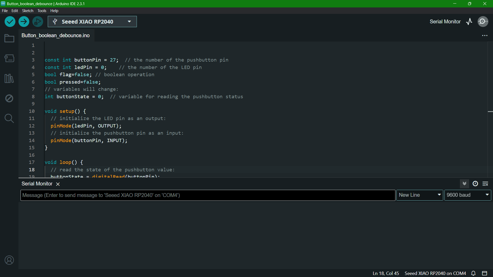
Here's the modified code I did in order to get the informations about LED ON/OFF states and Button Press at baud rate 9600.
const int buttonPin = 27;  // the number of the pushbutton pin
const int ledPin = 0;    // the number of the LED pin

int buttonState = 0;  // variable for reading the pushbutton status
int LEDState=0; // variable for reading the LED status

void setup() {
  Serial.begin(9600);
  // initialize the LED pin as an output:
  pinMode(ledPin, OUTPUT);
  // initialize the pushbutton pin as an input:
  pinMode(buttonPin, INPUT);
}

void loop() {
  // read the state of the pushbutton value:
  buttonState = digitalRead(buttonPin);
  if (buttonState==HIGH){
    Serial.println("Button Pressed"); //print
    // read the state of the LED value:
     LEDState = digitalRead(ledPin);
     if (LEDState==HIGH){
      Serial.println("LED Off"); //print
      digitalWrite(ledPin,LOW);
     } else {
      Serial.println("LED On");
      digitalWrite(ledPin,HIGH); //print
     }
     delay(200);
  }
}
Recursive Function
A recursive function is a function that calls itself during its execution. This enables the function to repeat its behavior until it reaches a base condition, which is a condition that stops the recursion to prevent it from executing indefinitely. Recursive functions are widely used in programming and computer science for tasks that can be broken down into similar subtasks, such as sorting, searching, and traversing complex structures like trees and graphs.
With the help of ChatGPT 3.5, I modified a code to toggle the LEDs sequentially with each button press using recursive function.
I pasted the code I created to toggle one LED on ChatGPT, and gave the prompt "Edit the code to light the three LEDs sequentially with each button press using recursive function."
    const int buttonPin = 27; // Button pin
    const int ledPins[] = {26, 0, 1}; // LED pins
    const int numLeds = 3; // Number of LEDs
    int ledIndex = 0; // Current LED index
    bool previousButtonState = HIGH; // Previous button state, assuming pull-up

    void setup() {
      for (int i = 0; i < numLeds; i++)
      {
        pinMode(ledPins[i], OUTPUT); // Initialize LED pins as output
      }
      pinMode(buttonPin, INPUT_PULLUP); // Initialize button pin as input with pull-up resistor
    }

    void loop() {
      bool currentButtonState = digitalRead(buttonPin);
      if (currentButtonState == LOW && previousButtonState == HIGH) {
        // Button was pressed
        blinkLedsRecursively(0); // Start blinking sequence
      }
      previousButtonState = currentButtonState; // Update the previous button state
    }

    void blinkLedsRecursively(int index) //recursive function
    {
      if (index >= numLeds) return; // Base case: stop if past the last LED

      digitalWrite(ledPins[index], HIGH); // Turn on current LED
      delay(500); // Wait for half a second
      digitalWrite(ledPins[index], LOW); // Turn off current LED

      blinkLedsRecursively(index + 1); // Recursively call for the next LED
    }
Using MicroPython
After completing all the essential part of this week's assignment, we moved on to program the XIAO RP2040 with MicroPython. I followed a tutorial to learn about the process.
Seeed Studio XIAO RP2040 with MicroPythonMicropython is a lean and efficient implementation of the Python 3 programming language that includes a small subset of the Python standard library and is optimized to run on microcontrollers and in constrained environments.
Key Features of MicroPython:
Setup
First, I downloaded and installed Thonny Editor.
Thonny is an Integrated Development Environment (IDE) designed especially for beginners learning Python programming. Its simplicity and straightforward interface make it an excellent choice for those new to programming, as well as for more experienced developers seeking a lightweight tool.
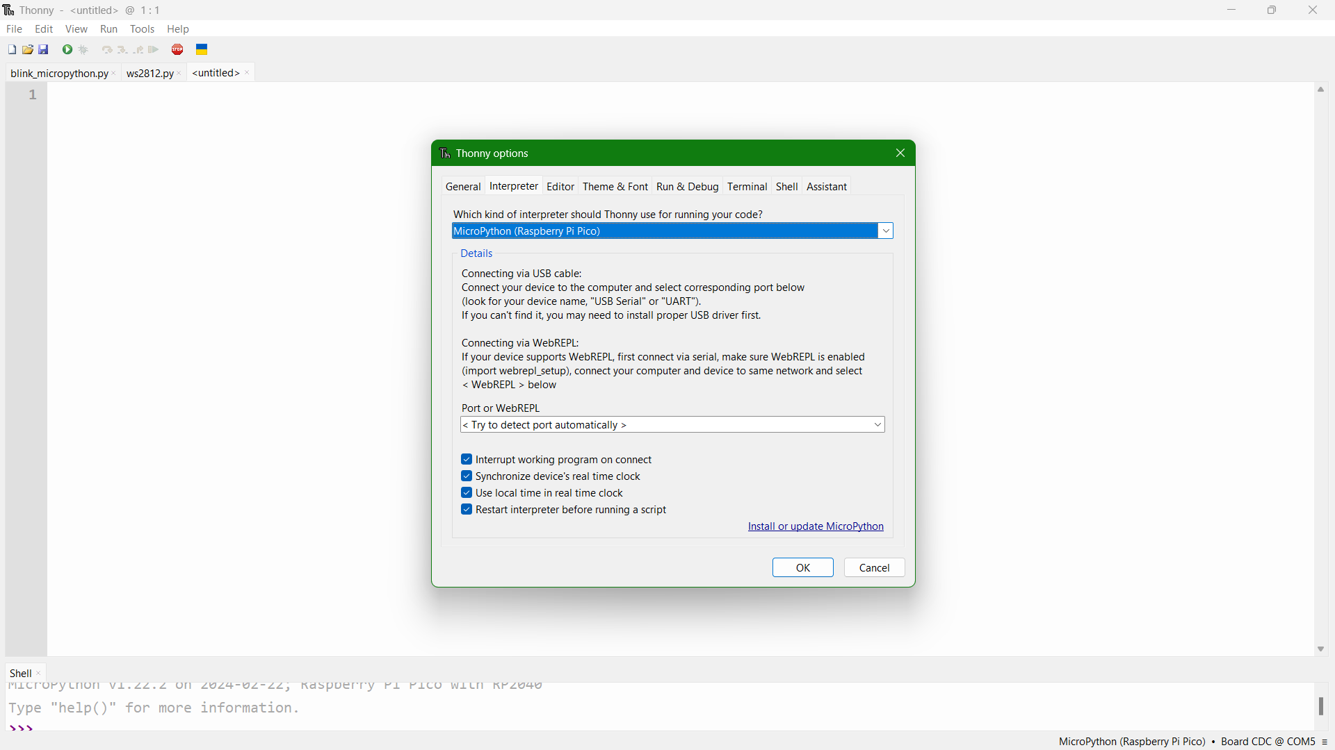
After installing, I added the interpreter as 'MicroPython(Raspberry Pi Pico)' from Tools > Options > Interpreter. Then, I pressed the 'BOOT, button on the board and connected it to the system. Then, 'RPI-RP2' desk pops up and then click on Install or update MicroPython. Select the MicroPython variant as Raspberry Pi Pico / Pico H. Click 'OK'.
Then, I copied the code provided in the tutorial and ran the code.
Code
    from machine import Pin, Timer

    led = Pin(25, Pin.OUT)
    Counter = 0
    Fun_Num = 0

    def fun(tim):
        global Counter
        Counter = Counter + 1
        print(Counter)
        led.value(Counter%2)

    tim = Timer(-1)
    tim.init(period=1000, mode=Timer.PERIODIC, callback=fun)
Next code provided on the tutorial was to light op the RGB LED on the Seeed Studio XIAO RP2040. I downloaded the library ws2812.py and saved it in Thonny.
Once done, I copied the code provided in tutorial.
Code
    from ws2812 import WS2812
import utime
import machine
power = machine.Pin(11,machine.Pin.OUT)
power.value(1)
BLACK = (0, 0, 0)
RED = (255, 0, 0)
YELLOW = (255, 150, 0)
GREEN = (0, 255, 0)
CYAN = (0, 255, 255)
BLUE = (0, 0, 255)
PURPLE = (180, 0, 255)
WHITE = (255, 255, 255)
COLORS = (BLACK, RED, YELLOW, GREEN, CYAN, BLUE, PURPLE, WHITE)

led = WS2812(12,1)#WS2812(pin_num,led_count)

while True:
    print("Beautiful color")
    for color in COLORS:
        led.pixels_fill(color)
        led.pixels_show()
        utime.sleep(0.2)
Using a Radar Sensor for Motion Detection
Radar Sensor
A radar sensor is a device that converts microwave echo signals into electrical signals. It uses wireless sensing technology to detect motion by figuring out the object's position, shape, motion characteristics, and motion trajectory.
How Radar Sensors Work
- Emission of Radio Waves: The radar emits radio waves using an antenna. These waves travel through the air until they hit an object.
- Reflection of Waves: Once the radio waves hit an object, they bounce back towards the radar system. The characteristics of the reflected waves can change based on the object's size, shape, and material.
- Reception of Echo: The radar sensor's antenna receives the reflected waves. The time it takes for the waves to return is measured.
- Analysis of Signal: The radar system analyzes the received signal to determine the distance (range), speed (velocity), and angle (direction) of the object relative to the sensor. This is done by calculating the time delay between the transmitted and received waves and analyzing the Doppler shift (change in frequency of the wave due to the movement of the object) for speed.
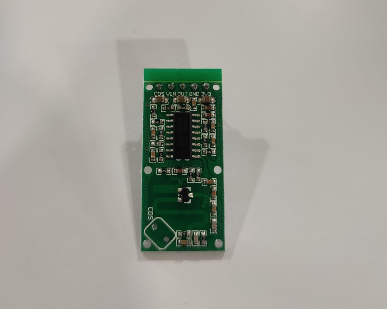
RCWL-0516
I used RCWL-0516 Microwave Radar Sensor in my work. It detects motion and unlike traditional infrared (PIR) sensors, which require the infrared signature of a moving person or animal to detect motion, the RCWL-0516 uses microwave Doppler radar technology to sense motion through doors, walls, or glass. This capability makes it useful for applications where non-line-of-sight motion detection is desirable, such as automatic lighting, security systems, and projects that require motion detection without the limitations of direct line of sight.
Key features of RCWL-0516:
- Operating Frequency: Typically around 3.2 GHz, which is in the microwave range.
- Detection Range: It can detect motion up to approximately 5-7 meters away, depending on the conditions and materials between the sensor and the moving object.
- Power Supply Requirements: It typically operates at 5V DC, making it compatible with many microcontrollers and development boards like Arduino, ESP8266, and Raspberry Pi for hobbyist and educational projects.
- Low Power Consumption: It is suitable for battery-powered applications.
- Compact Size:Compact Size: This makes it easy to integrate into projects or devices where space is limited.
- Sensitivity: It can be adjusted by using specific components (e.g., resistors) on the module, although this might vary by specific designs or versions of the module.
- Trigger Mode: The module outputs a high signal for a short period (typically 2-3 seconds) when motion is detected, and then returns to low.
Click to download RCWL0516-Datasheet
Process
Components
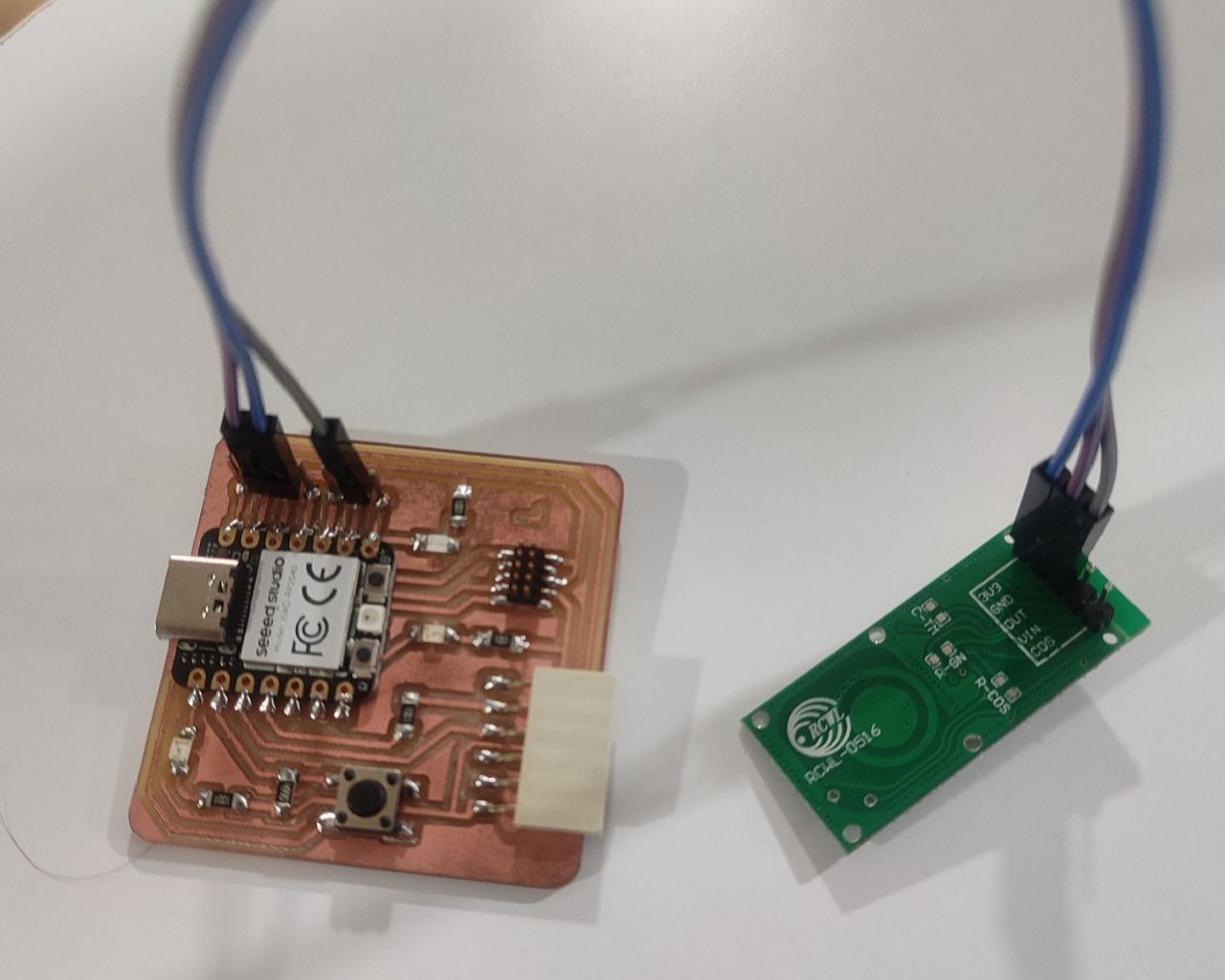
- Xiao RP2040 development board (Quentorres)
- RCWL-0516 radar motion sensor module
- Jumper Wires x3
- Headers x2
Connecting RCWL-0516 to Xiao RP2040
- First I soldered headers to both the sensor module and RP2040.
- Connections using Jumper Wires
- Connect the 3V3 (VCC) pin of the RCWL-0516 to one of the 3.3V pins on the Xiao RP2040.
- Connect the GND pin of the RCWL-0516 to one of the GND pins on the Xiao RP2040.
- Connect the OUT pin of the RCWL-0516 to one of the digital GPIO pins on the Xiao RP2040. Here, I connected it to pin 2.
I chose MicroPython language and Thonny as my IDE. With the help of ChatGPT, I generated a simple code to light up an LED if motion is detected and to print the same.
Code
from machine import Pin
import time
# Initialize GPIO 2 as input for the RCWL-0516 motion sensor
motion_sensor = Pin(2, Pin.IN)
# Initialize GPIO 1 as output for the LED
led = Pin(1, Pin.OUT)
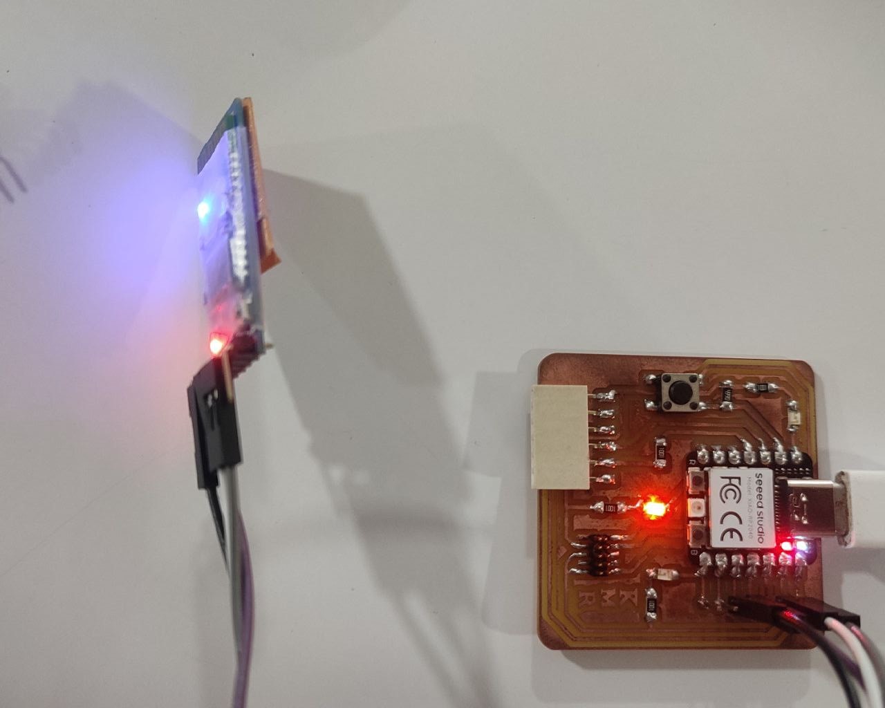
while True:
if motion_sensor.value() == 1: # Check if motion is detected
led.value(1) # Turn on the LED
print("Motion detected! LED turned on.")
time.sleep(5) # Keep the LED on for 5 seconds
else:
led.value(0) # Turn off the LED
print("No motion. LED turned off.")
time.sleep(0.5) # Check for motion every half second
Wireless Communication
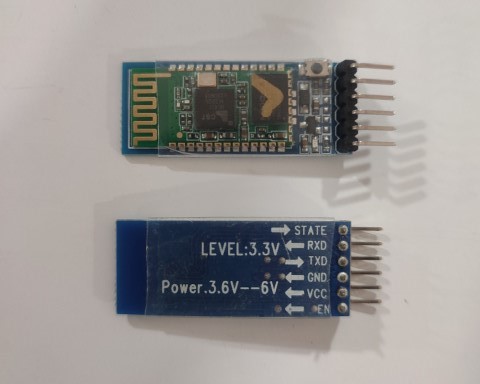
HC-05 Bluetooth Module
The HC-05 is a widely used Bluetooth module that enables wireless communication between devices. It's commonly employed in various electronics projects, including those with Arduino and other microcontroller platforms. The HC-05 can function as both a Bluetooth master and slave device, which allows it to both initiate and accept connections.
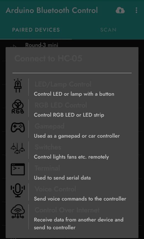
Arduino Bluetooth Controller
The "Arduino Bluetooth Controller" app is a versatile and user-friendly mobile application designed to facilitate wireless communication and control between a board and a smartphone or tablet via Bluetooth technology. This app serves as a bridge to send and receive data to/from a circuit, allowing users to control various projects and devices remotely. The app provides multiple built-in codes that perform various processes as below:
Process
Components
- Xiao RP2040 development board (Quentorres)
- HC-05 Bluetooth Module
- Jumper Wires x4
Connecting HC-05 to Xiao RP2040
- Connections using Jumper Wires
- Connect the 3V3 (VCC) pin of the HC-05 to one of the 3.3V pins on the Xiao RP2040.
- Connect the GND pin of the HC-05 to one of the GND pins on the Xiao RP2040.
- Connect the TX pin of the HC-05 to the RX pin (Pin 1) on the Xiao RP2040.
- Connect the RX pin of the HC-05 to Pin 2 on the Xiao RP2040.
Note: We tried using UART for the connection between the module and board but it was not working. So, we had to resort to the pins of the XIAO RP2040.
We used Arduino IDE for running the code.
Code
    #include < Arduino.h >
    #include < SoftwareSerial.h >

    const int ledPin = 0; // GPIO pin for the LED
    SoftwareSerial bluetoothSerial(3, 4); // RX, TX pins for HC-05

    void setup() {
      Serial.begin(9600);          // Initialize the serial communication for debugging
      bluetoothSerial.begin(9600); // Initialize Bluetooth serial communication
      pinMode(ledPin, OUTPUT);      // Set the LED pin as an output
    }

    void loop() {
      if (bluetoothSerial.available() > 0) {
        char command = bluetoothSerial.read();

        // Toggle LED based on received command
        if (command == '1') {
          digitalWrite(ledPin, HIGH); // Turn on LED
          Serial.println("LED ON");
        } else if (command == '0') {
            digitalWrite(ledPin, LOW);  // Turn off LED
            Serial.println("LED OFF");
          }
      }
    }
PlatformIO IDE
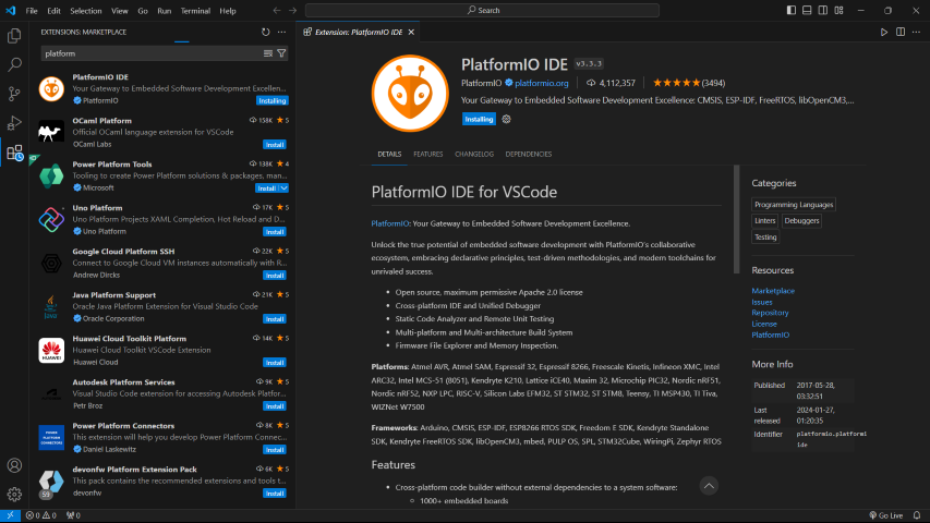
The PlatformIO IDE is an integrated development environment that's built upon Visual Studio Code (VSCode), designed to simplify the development process for various embedded systems and Internet of Things (IoT) applications. It supports a vast number of boards and microcontrollers, including Arduino, ESP8266, ESP32, STM32, and many others. Its extensive library database, multi-platform build system, and other features make it a powerful tool for developers. PlatformIO IDE is well-suited for more complex projects and for experienced users who need more advanced features.
Install PlatformIO Extension in VS Code:
1. Open VSCode.
2. Navigate to the Extensions view by clicking on the square icon on the sidebar or pressing Ctrl+Shift+X.
3. Search for "PlatformIO IDE".
4. Click on the install button.
 Creating a Project
Open PlatformIO Home: Once PlatformIO is installed, you'll see a PlatformIO icon on the sidebar. Click it to open the PlatformIO Home screen.
Create a New Project:
Creating a Project
Open PlatformIO Home: Once PlatformIO is installed, you'll see a PlatformIO icon on the sidebar. Click it to open the PlatformIO Home screen.
Create a New Project:
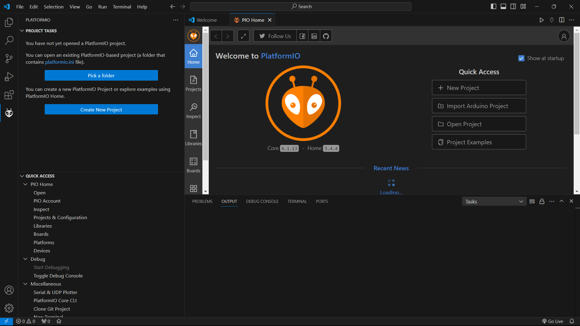 1. In the PlatformIO Home screen, click on "New Project".
2. Enter a name for the project.
3. Select the board. Here, I chose Raspberry Pi Pico because they don't have Seeed Studio XIAO RP2040.
4. Choose the framework (I chose Arduino for my project).
5. Click "Finish". PlatformIO will create the project structure.
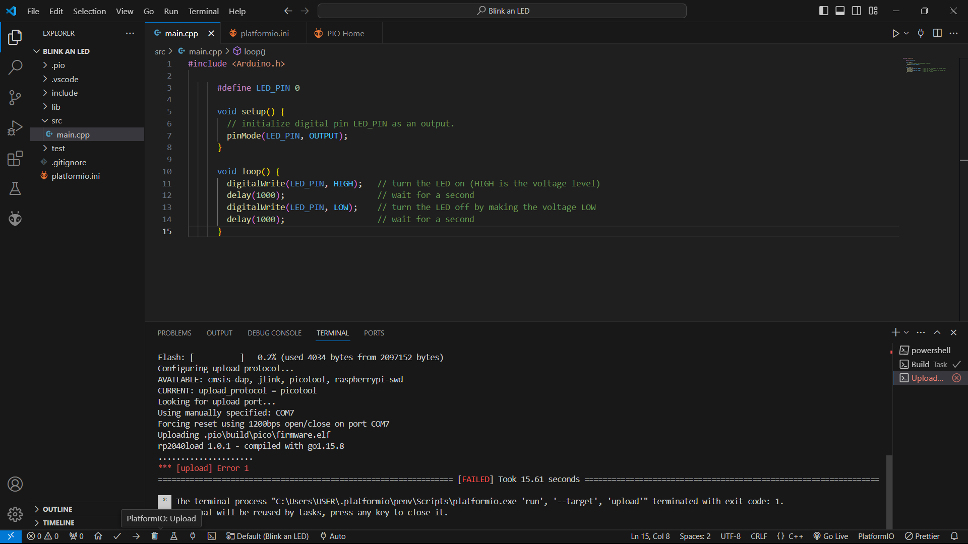
In order to add the code, navigate to the 'src' folder in the project directory within VSCode. You'll find a main.cpp file there. The code is to be added here. In my case, I added a simple code of blinking an LED.
Code
    #include

      #define LED_PIN 0

      void setup() {
        // initialize digital pin LED_PIN as an output.
        pinMode(LED_PIN, OUTPUT);
      }

      void loop() {
        digitalWrite(LED_PIN, HIGH);   // turn the LED on (HIGH is the voltage level)
        delay(1000);                   // wait for a second
        digitalWrite(LED_PIN, LOW);    // turn the LED off by making the voltage LOW
        delay(1000);                   // wait for a second
      }
Building and Uploading the Project
Build: Click the checkmark icon at the bottom blue bar (PlatformIO Toolbar) to compile/build the project once the code is written.
Upload: Connect the board to the computer via USB. Then, click the right arrow icon next to the checkmark in the PlatformIO Toolbar to upload the code to the board.
Building the project was done successfully but it failed while uploading the code. Our instructors came for help but still it was failing. We havent given up hope, because still we are trying to make it work as PlatformIO can be a beneficial tool in my future work.
Group Assignment
This week's group assingment was to browse through the datasheet of Quentorres board and to compare the performance and development workflows for other architectures.
.jpg)
For further details, click on the link below.
Group Assignment-Week 6Download Files
Codes
    • LED Toggle with Boolean

    • Debouncing

    • Sequential Light with Button

    • Motion Detection (MicroPython)

    • Bluetooth Module