Wild Card - Embroidery Machine
During the wild card week, participants have the unique opportunity to explore and utilize machinery not typically featured in the FabAcademy Program. We can take advantage of this opportunity to expand our skill set and explore other technologies.
Assignments
- Design and produce something with a digital process (incorporating computer-aided design and manufacturing) not covered in another assignment, documenting the requirements that your assignment meets, and including everything necessary to reproduce
Hero Shots
Design and File Export
To create the design, I utilized Inkscape. For detailed instructions on how to navigate the software, please refer to week 01. Inkscape offers a plethora of extensions to enhance your design process. For the embroidery aspect, I employed the Ink/Stitch extension.
Design
The workflow for digital embroidery shares similarities with laser cutting. Various software options exist, each accommodating different source formats for generating embroidery patterns. While some software can convert raster images into stitchable patterns, vector file formats are generally preferred. Their inherent path-based structure makes them more conducive to generating tool paths, simplifying the process.
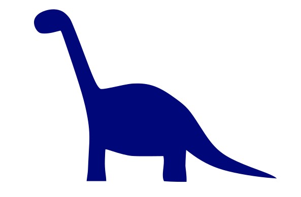
For the design, I utilized the Fabacademy Website logo, specifically focusing on the dinosaur element. Using Inkscape, I removed the background and employed logical operations to isolate the dinosaur for embroidery.
Ink/Stitch
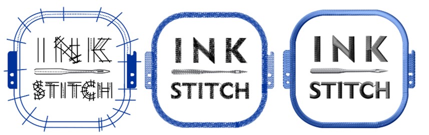
Ink/Stitch is a versatile, free, and open-source plugin designed for Inkscape, facilitating the preparation of machine code for various embroidery machines. Similar to how stroke types and colors in vector files are used in laser cutting to differentiate processes (such as marking, cutting, or engraving), in Ink/Stitch, stroke type and width determine the type and width of the stitch applied, if any. For a comprehensive overview of which strokes correspond to specific stitch patterns, refer to the Stitch Library section on the Ink/Stitch webpage.
In general, several considerations must be addressed when creating files for embroidery machines and managing the stitching process.
- Text Embroidering: To embroider text it is important to mentioned that not all fonts are supported by Ink/Stitch. For the best result use the ready to use fonts of Ink/Stitch
Extensions > Ink/Stitch > Lettering. If you still want to use another font it is important to change the text into a pathPath > Object to Path - Layers and Groups: By defining layers and grouping objects, you gain control over the workflow and the stitching sequence. It's important to note that the first layer defined will be embroidered first. Grouping objects allows you to consolidate them onto a single layer, streamlining the process. Additionally, depending on the embroidery machine being used, you can adjust colors and stitch types, and assign specific colors to different layers.
- Visual Commands: Visual commands play a crucial role in specifying additional instructions for embroidering your design. They serve various purposes, such as directing the machine to trim the thread after completing a specific embroidery element or indicating when to pause and where to stop. These commands are particularly useful for adding fabric layers to your appliqué design conveniently. (See here)
For this assignment's design, my goal was to create a filled embroidery of the dinosaur. To achieve this, I removed the outline and solely utilized the object's filling.
To ensure the stitches were executed as intended, I opened the simulation. Extension > Ink/Stich > Visualise and Export > Simulator/Realistic Preview.
The speed of stitching in the simulation. I used the default speed of 16 stiches/second .
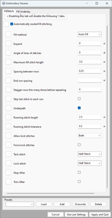
To few and change the default settings and have a better control of the outcome open Extension > Ink/Stich > Param.
In this window you can change setting per layer (to give different object different parameters put them to different layers). By changing the maximum stitches length as well as the spacing between the rows, the
thread covers more or less of the textile. I used the settings shown in the pictures (default settings).
As the simulation is also opened when opening the param window, the changes of the settings can be seen directly in the simulation.
After making sure that the simulation shows a flawless stitch the file can be exported as .dstr file.
Embroidery Machine
In our lab, we utilize the W6 N5000 sewing machine, which can be paired with various embroidery tables. These tables can be operated using either proprietary software provided with the machine or through Inkscape with the Ink/Stitch plugin. Our specific embroidery table model is the W6 EU-7, boasting a maximum embroidery size of 150 mm x 250 mm.
Set Up
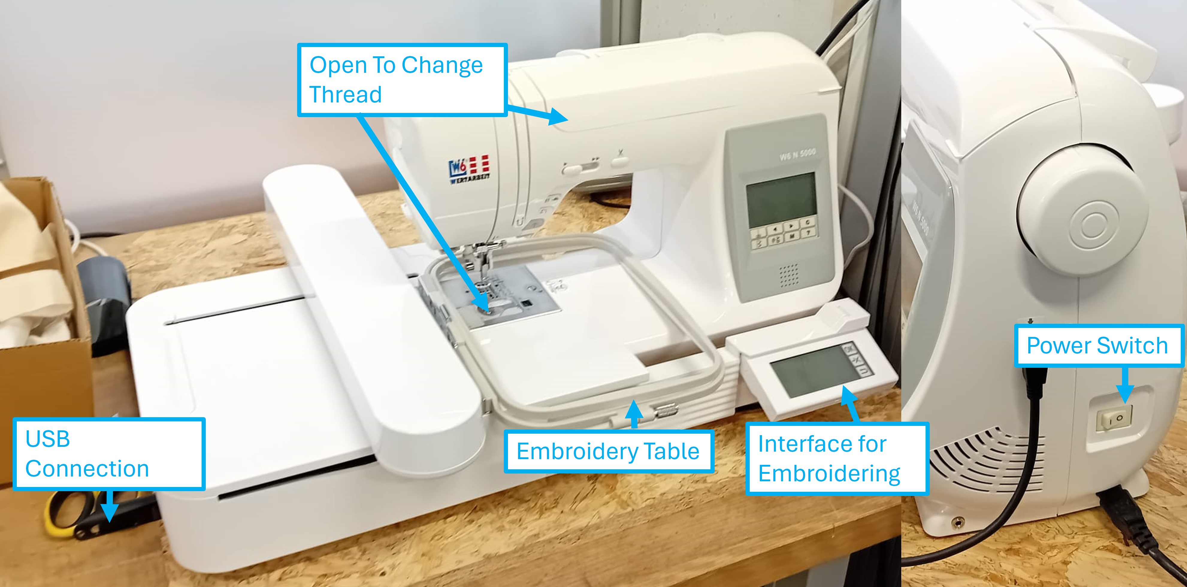
There are several steps to follow to set up the machine.
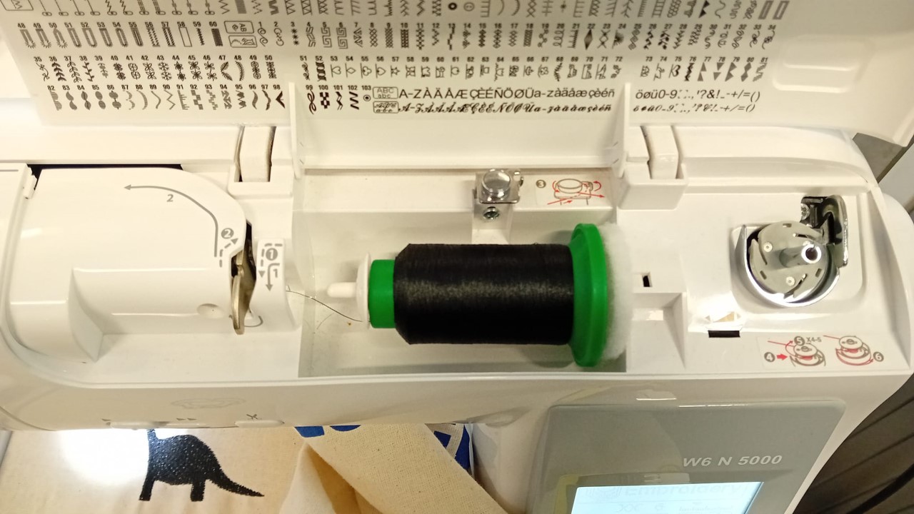
Changing the thread for another color involves opening the upper part of the machine and following the arrows and numbers on the machine to insert the thread.
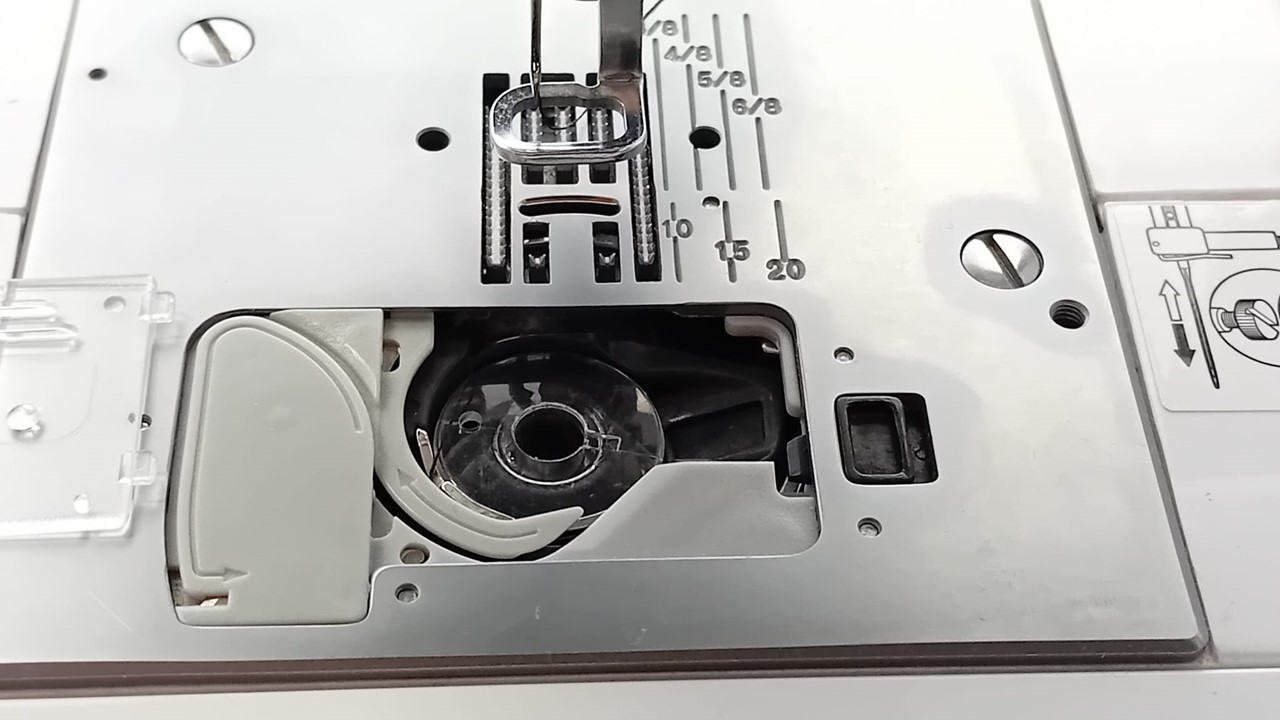
The second thread can be changed near the needle. It's important to follow the instructions on the machine during this process.
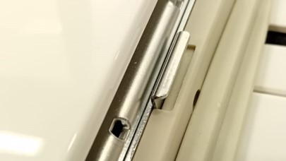
At the connection between the embroidery table and the machine, there si a small metal lash, which can be pressed down to release the embroidery table from the machine.
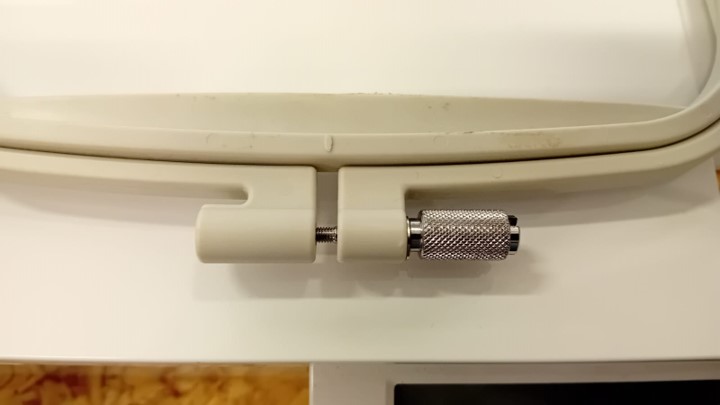
To span a piece of textile in the embroidery table this nut as to be loosen until the two pieces of the embroidery table can be separated and the piece of textil can be secured in between these two pieces.
Operation
To create an embroidered design, follow the instructions on the interface, though it may occasionally be challenging.
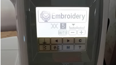
Before following the interface for automated embroidering, I used the upper interface to adjust the thread tension to 6.
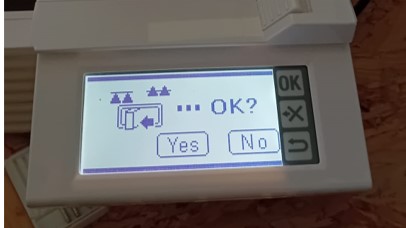
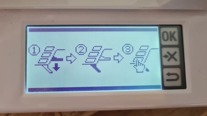
The bottom screen requests confirmation that the drop feed lever is in the correct position.
Next, the machine needs to home, which is done by confirming on the screen again.
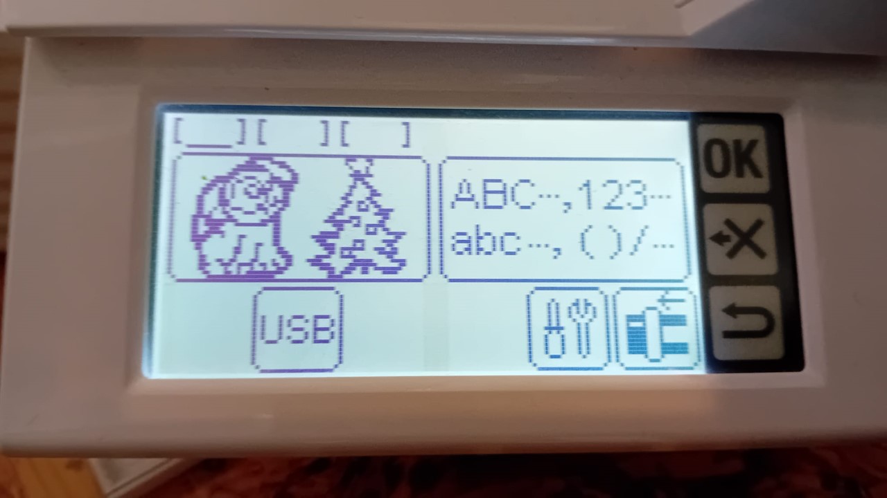
The display shows options to select USB or create a design using the options of the machine.
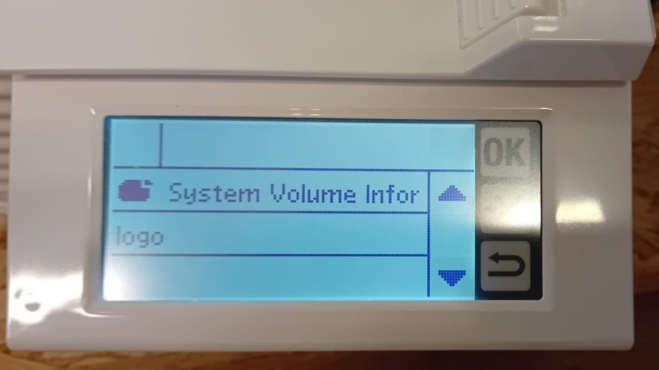
After plugging in the USB flash drive, the correct file can be selected.
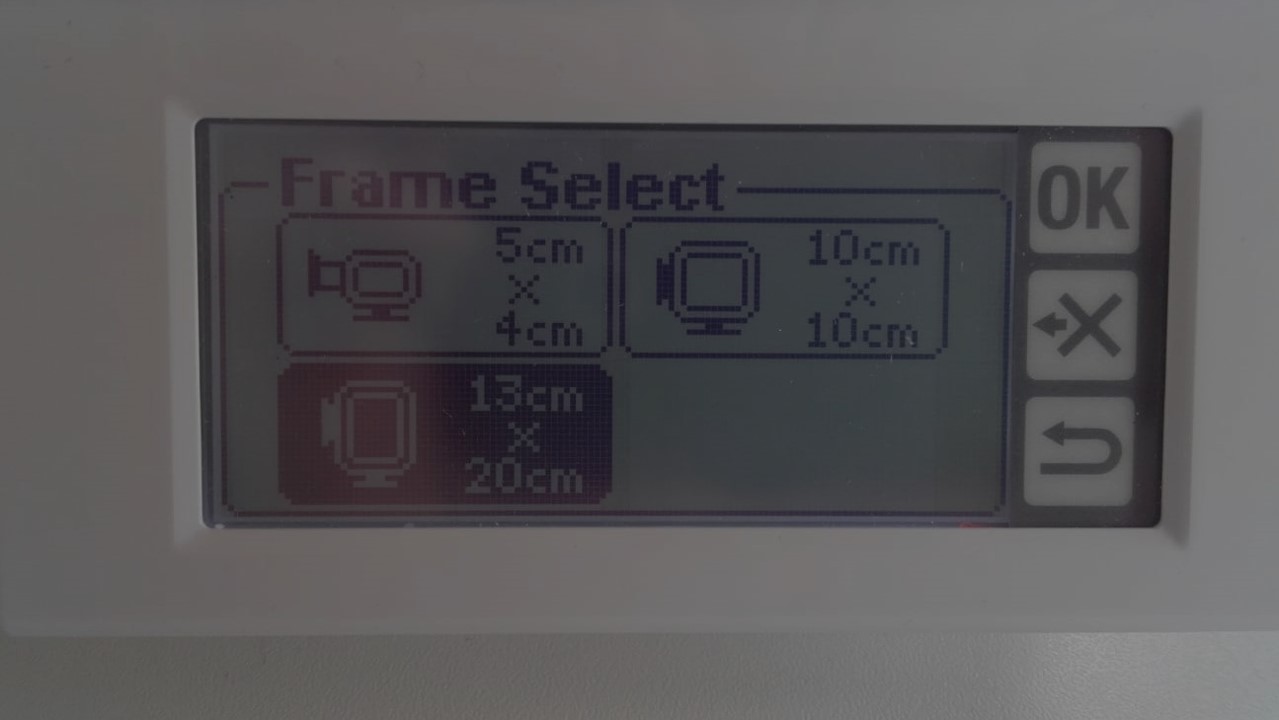
Next, the size of the embroidery table can be selected. Since we have the largest table, I chose that one.
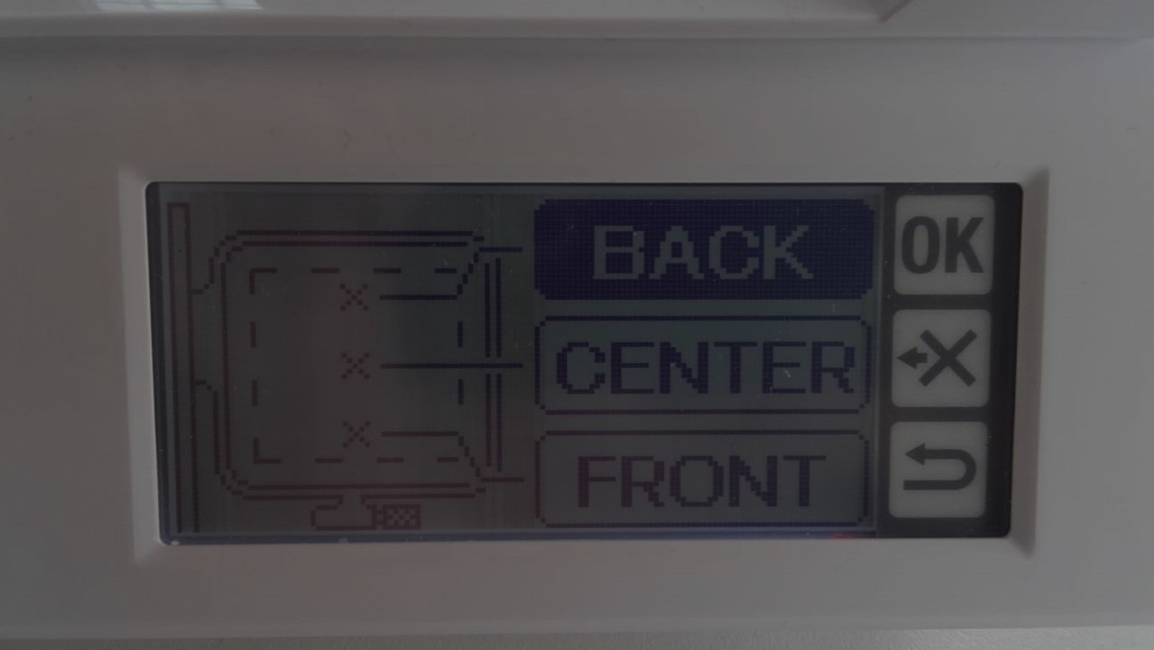
After this, the user is presented with three options: front, back, and center. These options do not correspond to the position of the design on the frame but to the position where the thread color change should take place.
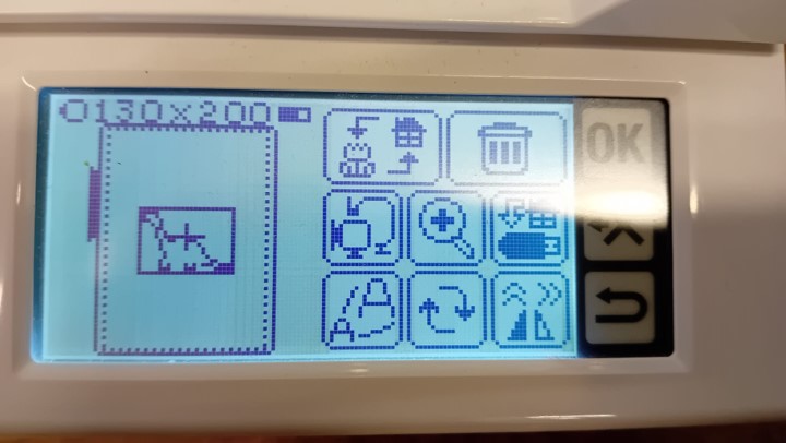
After that, a menu is displayed on the screen. I clicked on the symbol in the bottom right corner to adjust the position.
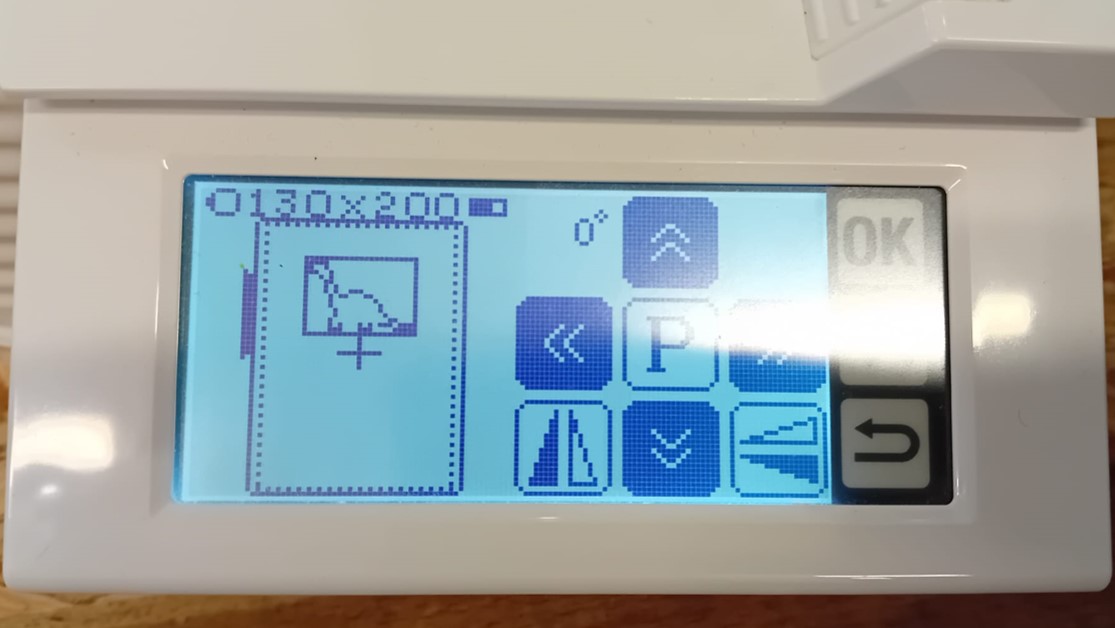
I positioned the design in the upper central part of the embroidery table. However, based on Frauke Waßmuth's embroidery, I noticed a better outcome when placing the design near the edge of the table.
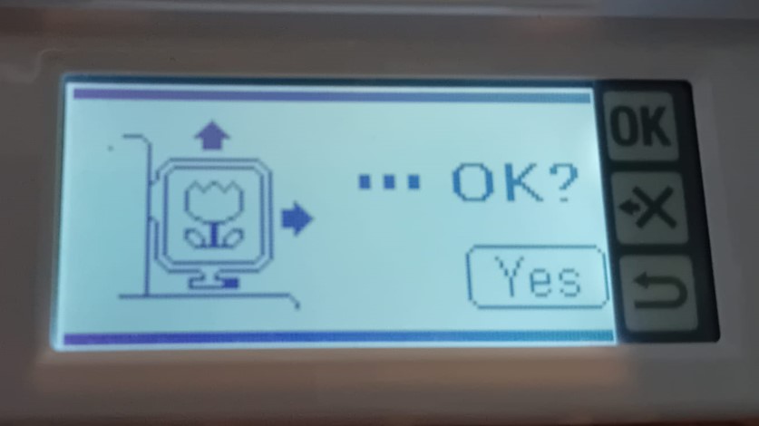
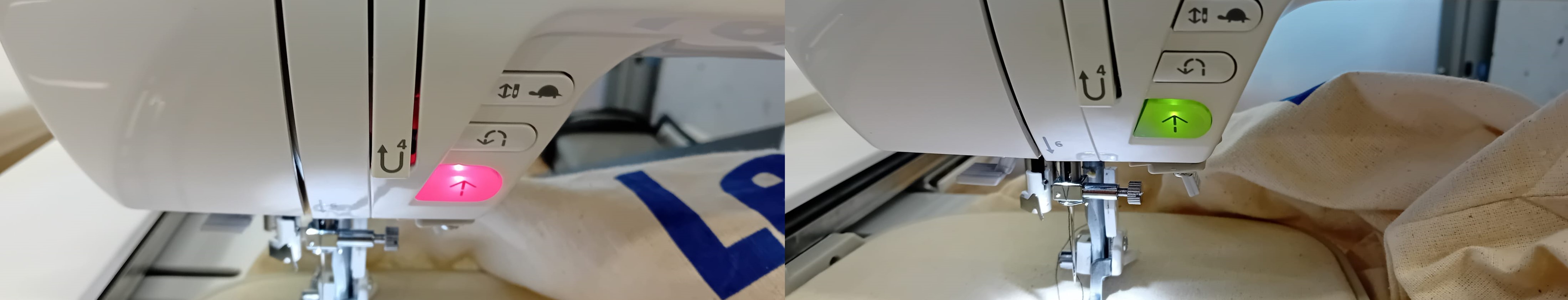
After pressing "OK" in the menu, the machine prompts whether the Presser Foot Lever is lowered.
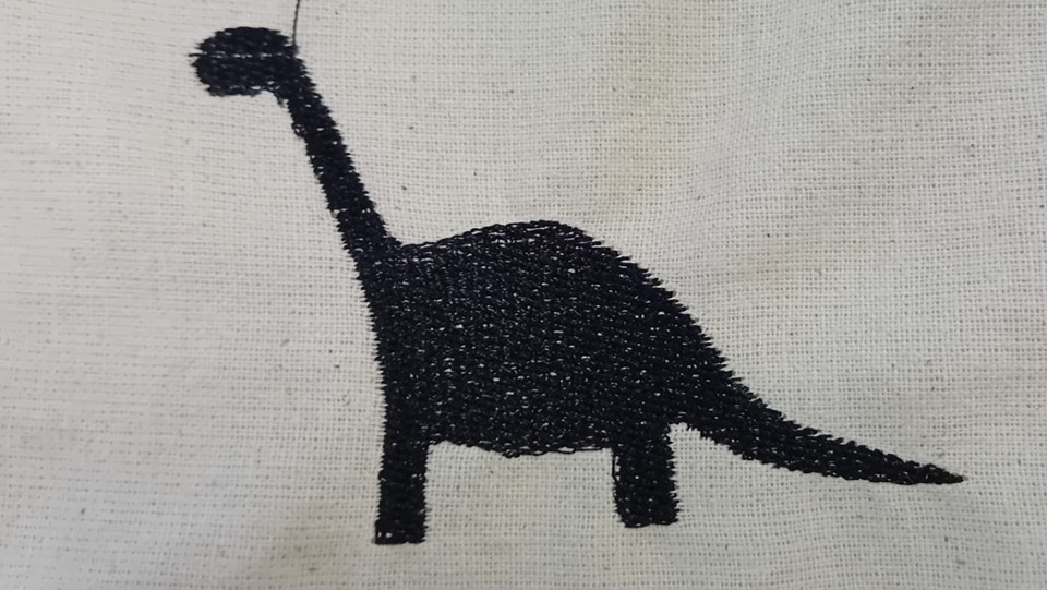
Embroidering of the Design
I am really happy with the outcome. Although, the density of the stitches could be a little higher , as parts of the textiles can be see through the threads. Therefore, a lower the spacing between the rows could have created a better outcome.