WEEK 11
Input Devices
Group Assignment:
- Probe an input device's analog levels and digital signals.
Individual Assignment:
- Measure something: add a sensor to a microcontroller board that you have designed and read it
1.What is a capacitive touch sensor?
In the input devices week; I worked on capacitive touch sensor which I already order for my final project.
Capacitive Sensing
Capacitive touch sensing is a method to detect when someone touches something without needing to press hard. It can sense touch even if there's some material like plastic, wood, or ceramic in between, but not metal. This means you can hide the sensor so it can't be seen easily.
How does it work?
The sensor plate and your body act like a capacitor. A capacitor holds electric charge. The bigger the capacitor, the more charge it can hold.
What does the Arduino do?
Basically, the Arduino measures how long it takes for the capacitor (the touch sensor) to charge up. This helps it figure out how much charge it can hold, which is called capacitance. Even if the capacitance is really small, the Arduino can still measure it accurately.
2. Circuit Design
To design the circuit, I used following components.
| My pcb design | Controlling the circuit . |
| RGB LED | Output device. |
| Capacitive touch sensor | Input device. |
| Jumper Wires | Connects the components together. |
| Breadboard | Allows communication of the input device and jumber cables. |
| 10K Resistor | Ensures that the analog signal at the output of the sensor remains within a readable voltage range. . |
| Type C Cable | Connects the PCB to the computer. |
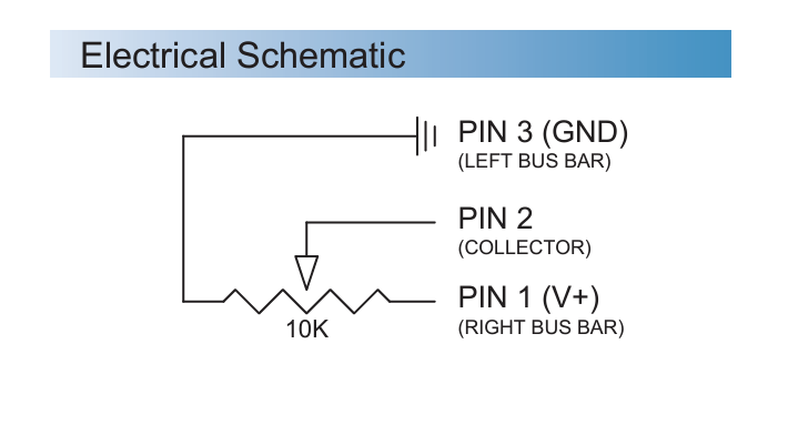
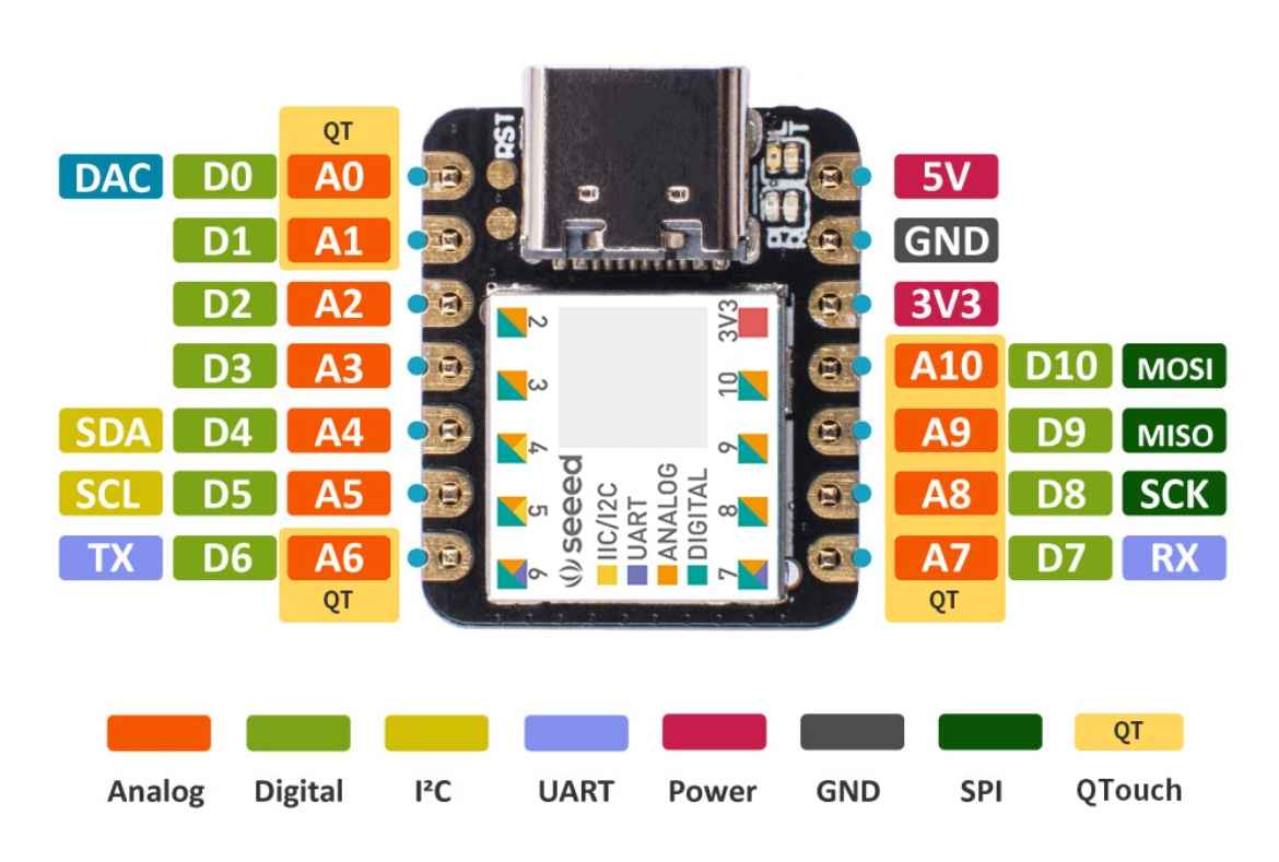
To design the circuit I found a schematic of the sensor to learn which pins I should connect to the PCB. Also to remember pin numbers of the PCB I used another schematic that I showed under the first schematic.
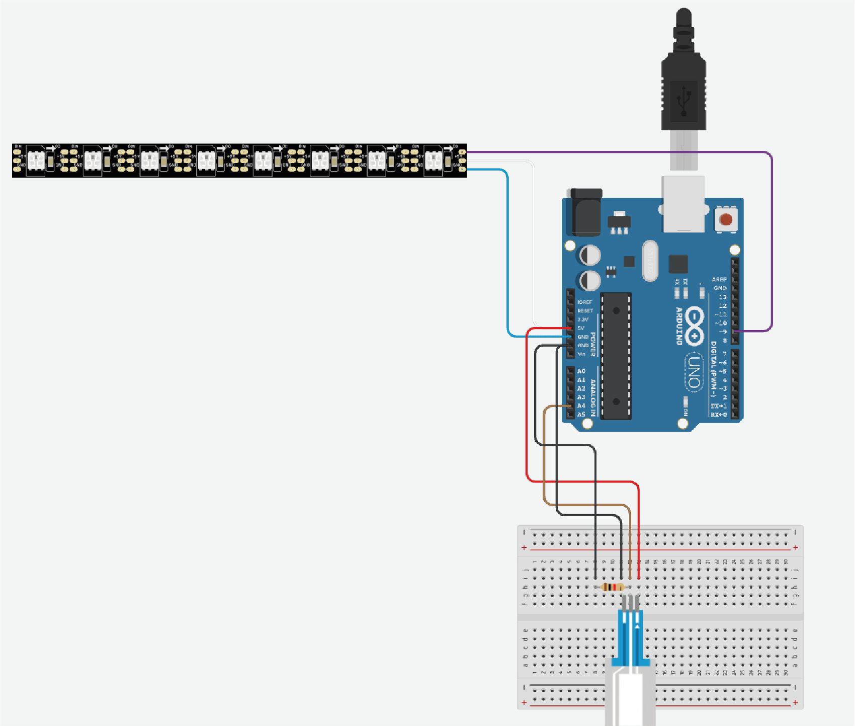
I connected all the components and created the circuit. Also, I had some challenges finding that ground pin in PCB however when I checked on my Kicad document I saw which pin is ground. In order to better explain the circuit I prepared, I prepared the following circuit image on the Tinkercad website.
3. Programing The PCB
I aimed to change LED brightness by pressing the sensor’s different places. At the beginning of the process, I found a capacitive touch sensor library on the Arduino website, However, my supervisor suggested that I use sensor code from another source.
I used that website to have my source code
Sensor code;
/******************************************************************************
SoftPot_Example.ino
Example sketch for SparkFun's soft membrane potentiometer
(https://www.sparkfun.com/products/8680)
Jim Lindblom @ SparkFun Electronics
April 28, 2016

- Connect the softpot's outside pins to 5V and GND (the outer pin with an arrow
indicator should be connected to GND).
- Connect the middle pin to A0.

As the voltage output of the softpot changes, a line graph printed to the
serial monitor should match the wiper's position.

Development environment specifics:
Arduino 1.6.7
******************************************************************************/
const int SOFT_POT_PIN = A0; // Pin connected to softpot wiper

const int GRAPH_LENGTH = 40; // Length of line graph

void setup()
{
Serial.begin(9600);
pinMode(SOFT_POT_PIN, INPUT);
}

void loop()
{
// Read in the soft pot's ADC value
int softPotADC = analogRead(SOFT_POT_PIN);
// Map the 0-1023 value to 0-40
int softPotPosition = map(softPotADC, 0, 1023, 0, GRAPH_LENGTH);

// Print a line graph:
Serial.print("<"); // Starting end
for (int i=0; i (" + String(softPotADC) + ")");

delay(500);
}
Also, I useD NeoPixel LED code from my Arduino Library.
// NeoPixel Ring simple sketch (c) 2013 Shae Erisson
// Released under the GPLv3 license to match the rest of the
// Adafruit NeoPixel library

#include
#ifdef __AVR__
#include  // Required for 16 MHz Adafruit Trinket
#endif

// Which pin on the Arduino is connected to the NeoPixels?
#define PIN        9 // On Trinket or Gemma, suggest changing this to 1

// How many NeoPixels are attached to the Arduino?
#define NUMPIXELS 16 // Popular NeoPixel ring size

// When setting up the NeoPixel library, we tell it how many pixels,
// and which pin to use to send signals. Note that for older NeoPixel
// strips you might need to change the third parameter -- see the
// strandtest example for more information on possible values.
Adafruit_NeoPixel pixels(NUMPIXELS, PIN, NEO_GRB + NEO_KHZ800);

#define DELAYVAL 500 // Time (in milliseconds) to pause between pixels

void setup()
// These lines are specifically to support the Adafruit Trinket 5V 16 MHz.
// Any other board, you can remove this part (but no harm leaving it):
#if defined(__AVR_ATtiny85__) && (F_CPU == 16000000)
clock_prescale_set(clock_div_1);
#endif
// END of Trinket-specific code.

pixels.begin(); // INITIALIZE NeoPixel strip object (REQUIRED)

pixels.clear(); // Set all pixel colors to 'off'
To control the LED brightness by using the touch sensor, I combined these two source codes and transferred them to my PCB. You can find the code below with the explanations next to it.
#include  // This library controls the NeoPixel LEDs.

const int SOFT_POT_PIN = A4; // Pin connected to softpot wiper

// The analog pin A4 is connected to the wiper of the soft potentiometer.

const int GRAPH_LENGTH = 40; // Length of line graph

// This is used to map the softpot readings to a value between 0 and 40.

// Which pin on the Arduino is connected to the NeoPixels?
#define PIN        9 // Pin on the Arduino connected to the NeoPixels

// How many NeoPixels are attached to the Arduino?
#define NUMPIXELS 8 // There are 8 NeoPixels in the strip.


Adafruit_NeoPixel pixels(NUMPIXELS, PIN, NEO_GRB + NEO_KHZ800);
// Creates an instance of the NeoPixel object with 8 LEDs on pin 9, using the GRB color order and 800 KHz signal.

#define DELAYVAL 50 // Delay between lighting each pixel

int colorG =0 ;
int colorR =0 ;
int colorB=0 ;


void setup()
{
Serial.begin(9600);
pinMode(SOFT_POT_PIN, INPUT); // Sets the soft potentiometer pin as an input.
pixels.begin(); // INITIALIZE NeoPixel strip object (REQUIRED)

}

void loop()
{
// Read in the soft pot's ADC value
int softPotADC = analogRead(SOFT_POT_PIN); // Reads the value from the soft potentiometer (0-1023).
Serial.println(softPotADC); // Prints the ADC value to the serial monitor.

int softPotPosition = map(softPotADC, 0, 4095, 0, GRAPH_LENGTH);
colorG = map(softPotADC, 0, 1023, 0, 255);
colorR = map(softPotADC, 0, 1023, 0, 255);
colorB = map(softPotADC, 0, 1023, 0, 255);

//delay(500);
ledStrip();
}

void ledStrip() {
	pixels.clear(); // Turns off all pixels.

	// The first NeoPixel in a strand is #0, second is 1, all the way up
	// to the count of pixels minus one.
	for(int i=0; i< NUMPIXELS; i++) { // For each pixel...

	  // pixels.Color() takes RGB values, from 0,0,0 up to 255,255,255
	  // Here we're using a moderately bright green color:
	  pixels.setPixelColor(i, pixels.Color(colorR, colorG, colorB));

	  pixels.show();   // Updates the hardware with the new pixel colors.

	  //delay(DELAYVAL); //  Pauses for 50 milliseconds between lighting each pixel.
	}
  }
Explanation of the code;
- The code reads the sensor value and prints it.
- The sensor value is mapped to RGB values.
- The ledStrip function updates the NeoPixel strip with the new color.
- The NeoPixel strip lights up with the color determined by the potentiometer position.
- I connected the PCB to my computer via a usb cable.
- I opened the Arduino IDE application and found my PCB by following this path. Tools--- Board --- SeeeduinoXIAO
- I followed this path to find the port that connects to the PCB. Tools--- Port --- USB modern
- I placed the required code in the software.
- After having the code, I sent the code to the pcb by clicking on the arrow in the upper left corner of the application.
- Now, when I press different parts of the sensor, some data should go to the computer. To check this, I opened the serial monitor tab in the Arduino IDE software.
- I opened the serial monitor screen by clicking on the magnifying glass icon in the upper right corner of the interface. I saw that I got different values when I pressed different parts of the sensor.
4. Test
I connected my circuit to the PCB to have power and test it. And I saw my circuit is working. If I press the left side of the slider there is less LED brightness compared to when I press right side of the slider. I followed the steps below to test the sensor;
As seen in the videos, the value on the serial monitor changes according to the area touched by the sensor. Depending on the length of the sensor, when I touch close to the starting point, a small value is observed in the serial monitor and a large value is observed as I move away from the starting point. These values are between 0-1023. We can also see this in the code line. The largest value that can be read from the sensor is set to 1023 and the smallest value is set to 0. Also, when I raise my hand, the value drops to 0 again. But for my final project I need the code to maintain reading the last value. For this reason, the second step for me is to ensure that the last read value is maintained.
5. IMPLEMENTATION TO THE FINAL PROJECT
In my final project, I placed the touch sensor in the main module. The user touches the sensor and a message is received. The received information is transmitted to the PCB to which the sensor is connected.
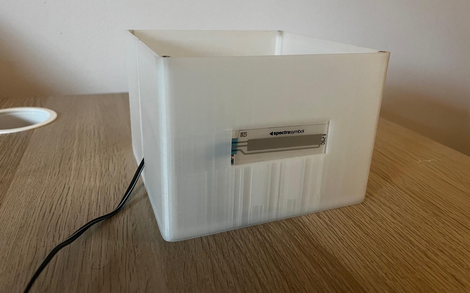
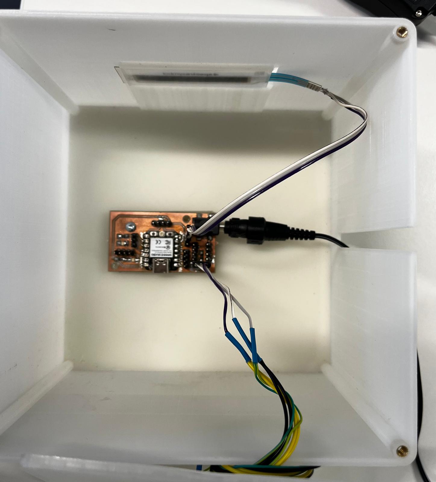
I soldered the wires to the sensor. I connected the other end of the cable to the PCB. The pin outputs to which the sensor is connected are as follows; ground, D5 and 5V.
I used following code for programming the LED and the touch sensor.
#include

const int SOFT_POT_PIN = A0; // Pin connected to softpot wiper

const int GRAPH_LENGTH = 8; // Length of line graph


// Which pin on the Arduino is connected to the NeoPixels?
#define PIN        D5 // On Trinket or Gemma, suggest changing this to 1

// How many NeoPixels are attached to the Arduino?
#define NUMPIXELS 180 // Popular NeoPixel ring size


Adafruit_NeoPixel pixels(NUMPIXELS, PIN, NEO_GRB + NEO_KHZ800);

#define DELAYVAL 50 // Time (in milliseconds) to pause between pixels

int brightness =0 ;

int oldBrigthness = 0;

int colorG =0 ;
int colorR =0 ;
int colorB=0 ;

int tempValue = 0;


void setup()
{
Serial.begin(9600);
pinMode(SOFT_POT_PIN, INPUT);
pixels.begin(); // INITIALIZE NeoPixel strip object (REQUIRED)

}

void loop()
{
// Read in the soft pot's ADC value
int softPotADC = analogRead(SOFT_POT_PIN);
//Serial.println(softPotADC);
// Map the 0-1023 value to 0-40
int softPotPosition = map(softPotADC, 0, 4095, 0, GRAPH_LENGTH);
tempValue = map(softPotPosition, 0, GRAPH_LENGTH, 0, 255);
Serial.println(tempValue);

if (tempValue != 0){
brightness=tempValue;
if (tempValue < 33) brightness=0;

if(brightness!=oldBrigthness)ledStrip();

}


/*colorG = map(softPotADC, 0, 1023, 0, 255);
colorR = map(softPotADC, 0, 1023, 0, 255);
colorB = map(softPotADC, 0, 1023, 0, 255);*/

//delay(500);
}

void ledStrip() {
pixels.clear(); // Set all pixel colors to 'off'

// The first NeoPixel in a strand is #0, second is 1, all the way up
// to the count of pixels minus one.
for(int i=0; i< NUMPIXELS; i++) { // For each pixel...

// pixels.Color() takes RGB values, from 0,0,0 up to 255,255,255
// Here we're using a moderately bright green color:
pixels.setPixelColor(i, pixels.Color(brightness, brightness, brightness));

pixels.show();   // Send the updated pixel colors to the hardware.

}
oldBrigthness=brightness;
}