
Week 9: Output Devices
Output: Image Based on Sensor Data
In continuing to use the circuitry assignments to create the components for my final project - I decided to build upon the progress from Circuit Design week, in which I was able to have the ESP32S3 output which sensor was being activated by a magnet. Now I needed to convert that sensor data into a corresponding 2D floorplan image.
To begin, I sketched out the various sensor configurations and what "2-D Floorplan Output Image" they should display on the screen. My first attempt was to simply use hotizontal and vertical lines from the standard keyboard characters to represent the orientation and type of tile.
Using a cardboard prototype with the hall sensors and magnets, I tested this code to see if it would accurately display the right tile design in Thonny.
I once again enlisted the help of ChatGPT to help me get the basic code framework to make this happen.
ChatGPT Prompt:
Im using a esp32-s3 wifi and want to have a frontend talk to it to draw the boxes based on the code on an esp32-s3. Here is my code "import board
import digitalio
import time
import wifi
import socketpool
# WiFi Configuration
SSID = "*********" # Replace with your WiFi SSID
PASSWORD = "*******" # Replace with your WiFi password
# Connect to WiFi
print("Starting WiFi connection process...")
try:
print(f"Attempting to connect to SSID: {SSID}")
wifi.radio.connect(SSID, PASSWORD)
print("Connected to WiFi")
print(f"IP Address: {wifi.radio.ipv4_address}")
except ConnectionError as e:
print(f"Failed to connect to WiFi: {e}")
while True:
pass # Halt execution if WiFi connection fails
# Set up the Hall sensor pins
hall_sensor_pins = [
digitalio.DigitalInOut(board.IO0),
digitalio.DigitalInOut(board.IO1),
digitalio.DigitalInOut(board.IO2),
digitalio.DigitalInOut(board.IO3),
]
# Configure each pin as input with a pull-up resistor
for i, pin in enumerate(hall_sensor_pins):
pin.direction = digitalio.Direction.INPUT
pin.pull = digitalio.Pull.UP # Enable internal pull-up resistor
print(f"Configured pin IO{i} as input with pull-up resistor")
def draw_box_with_lines(sensor_statuses):
box = [[" " for _ in range(10)] for _ in range(10)]
draw_top = False
draw_left = False
draw_right = False
draw_bottom = False
# Check for specific combinations first
if "D0" in sensor_statuses and "D1" in sensor_statuses and "D3" in sensor_statuses:
draw_top = True
draw_left = True
draw_right = True
elif "D0" in sensor_statuses and "D1" in sensor_statuses and "D2" in sensor_statuses:
draw_top = True
draw_right = True
draw_bottom = True
elif "D1" in sensor_statuses and "D2" in sensor_statuses and "D3" in sensor_statuses:
draw_left = True
draw_right = True
draw_bottom = True
elif "D0" in sensor_statuses and "D2" in sensor_statuses and "D3" in sensor_statuses:
draw_top = True
draw_left = True
draw_bottom = True
elif "D0" in sensor_statuses and "D1" in sensor_statuses and "D2" in sensor_statuses and "D3" in sensor_statuses:
draw_top = True
draw_left = True
draw_right = True
draw_bottom = True
elif "D0" in sensor_statuses and "D1" in sensor_statuses:
draw_top = True
draw_right = True
elif "D1" in sensor_statuses and "D2" in sensor_statuses:
draw_right = True
draw_bottom = True
elif "D2" in sensor_statuses and "D3" in sensor_statuses:
draw_left = True
draw_bottom = True
else:
for status in sensor_statuses:
if "D0" in status:
draw_top = True
if "D1" in status:
draw_right = True
if "D2" in status:
draw_bottom = True
if "D3" in status:
draw_left = True
# Draw the lines based on the flags
if draw_top:
for i in range(10):
box[0][i] = "-"
if draw_right:
for i in range(10):
box[i][9] = "|"
if draw_bottom:
for i in range(10):
box[9][i] = "-"
if draw_left:
for i in range(10):
box[i][0] = "|"
# Move cursor to the top of the console
print("\033[H", end="")
for row in box:
print("".join(row))
def check_magnets():
sensor_statuses = []
for i, pin in enumerate(hall_sensor_pins):
if not pin.value:
sensor_statuses.append(f"D{i}")
return sensor_statuses
# Clear the console and hide the cursor
print("\033[2J\033[?25l", end="")
try:
while True:
statuses = check_magnets()
print(f"Sensor statuses: {statuses}")
draw_box_with_lines(statuses)
time.sleep(1) # Check every 1 second
finally:
# Show the cursor again when exiting
print("\033[?25h", end="")
"
Text-Based Output
I loaded the code into the custom milled board from: Circuit Design Week and tested a new version of the code that would use the sensor combination to trigger an image instead of just text in the prompt. I used the wifi communication module on the ESP32S3 to display PNG images of the floorplan of each tile made on illustrator. I will dive deeper into that process in: Communications Week Page. When there were no sensors active, the page displayed a little question mark icon, so I decided to create a blank white square image when no sensors were active. The remaining images were named based on which sensors they were activating so it would be easier to rememeber when coding it. I made a thin outline image to represent a floor tile with no walls when all 4 sensors were activated.
Image Outputs:
D1

D2

D3

D4

D12

D14

D23

D34

D123

D124

D134

D234

D1234

PNG Image Output
Files
Download Code Download Display Images
Group Assignment
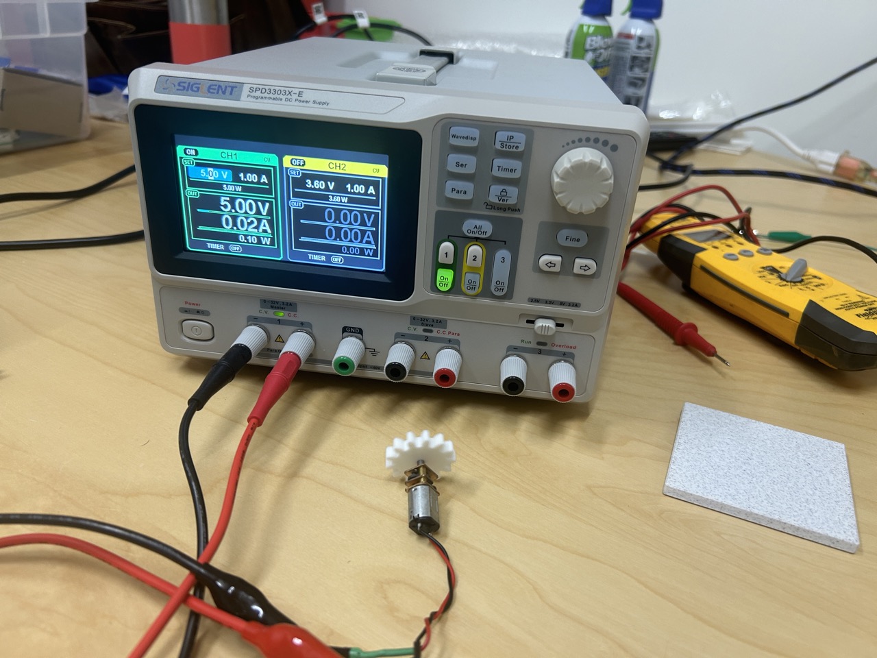
This week, we needed to check the power consumption of a component. Since we weren't using any high-power components in our lab, we decided to test the one with the highest draw: the motor in Peter's DAPR robot. Normally, you measure power consumption by connecting a multimeter in series with the component and power source to measure the current draw. The basic equation for power is:
Power
=
Current
X
Voltage
Power=Current X Voltage
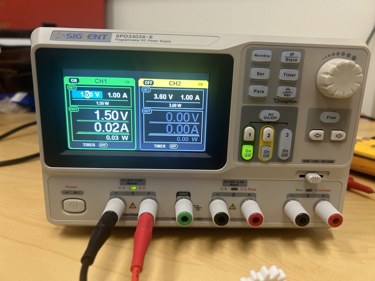 Using our power source, we set the voltage and let it read the current draw of the motor. We started at 5V, which is the max power draw from the microcontroller, and gradually reduced it to 0V to see the range of current draws. At 5V, our motor draws a current of 0.03A. Plugging that into the equation, it looks like this:
Power
=
0.03
A
X
5.0
V
Power=0.03A X 5.0V
Which calculates to:
Power
=
0.15
W
Power=0.15W
This isn't a big power draw, and since the robot runs on a 5000mAh battery, it means we can run this motor for a very long time.
Using our power source, we set the voltage and let it read the current draw of the motor. We started at 5V, which is the max power draw from the microcontroller, and gradually reduced it to 0V to see the range of current draws. At 5V, our motor draws a current of 0.03A. Plugging that into the equation, it looks like this:
Power
=
0.03
A
X
5.0
V
Power=0.03A X 5.0V
Which calculates to:
Power
=
0.15
W
Power=0.15W
This isn't a big power draw, and since the robot runs on a 5000mAh battery, it means we can run this motor for a very long time.
Power Supply Readouts
Copyright 2024 Thomas Pupo - Creative Commons Attribution Non Commercial
Source code hosted at fabcloud/fabacademy/2024/thomas-pupo