
Week 8: Electronics Design
This week, I will be using the assignment for the electronics board design to create a prototype for my final project - a board that uses hall sensors to identify a tile. I will create a single board with an ESP32S3 connecting 4 hall sensors and will test to ensure that the magnets trigger each hall sensor.
Step 1: Creating the Schematic
Start KiCAD and Create a New Project:
Open KiCAD and create a new project.
Add Components to the Schematic:
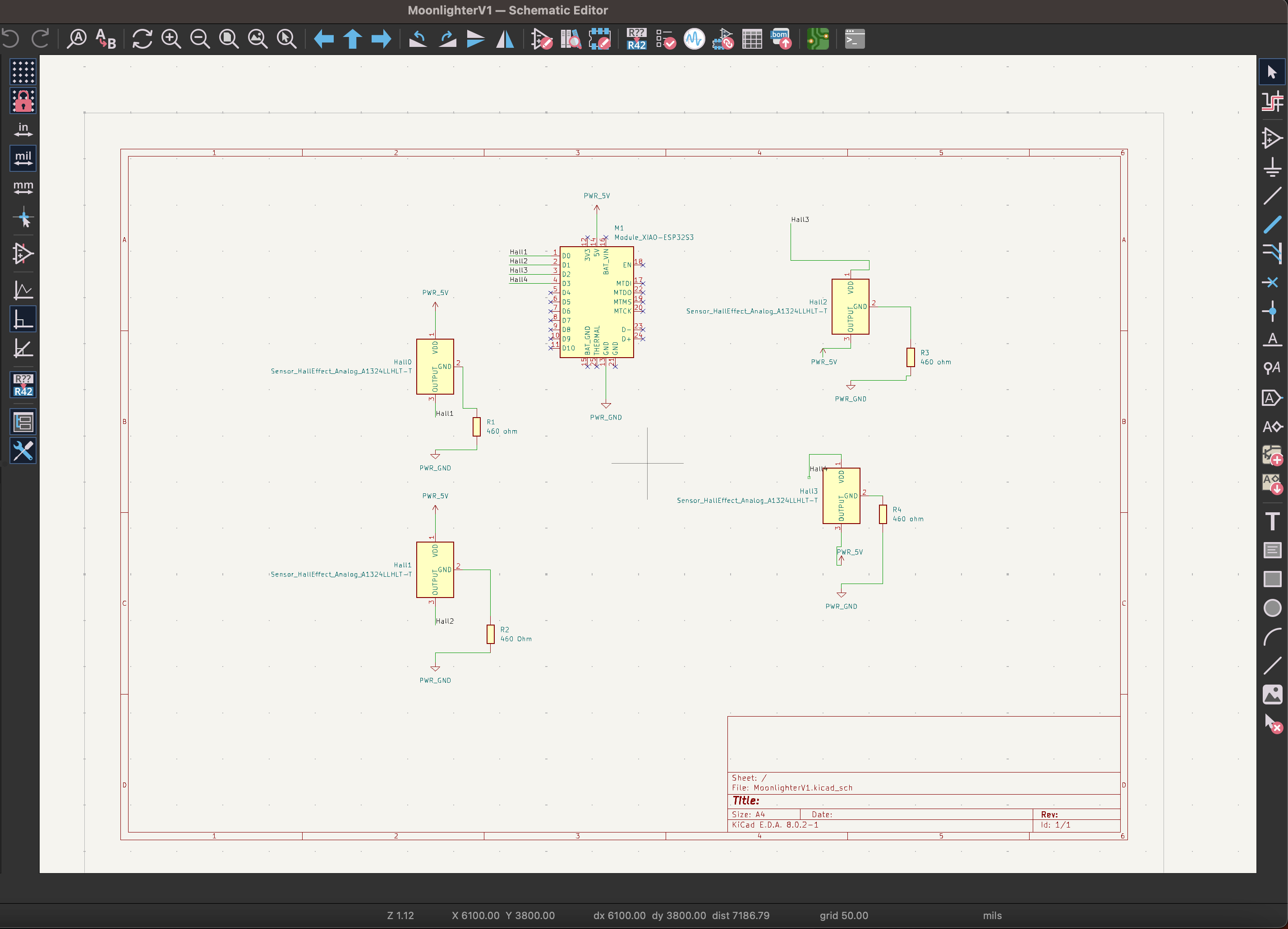
Open the schematic editor.
Add the ESP32-S3 microcontroller from the component library.
Add four hall sensors (e.g., A3144) to the schematic.
Add four 0-ohm resistors to the schematic.
Wire the Components:
Connect the VCC (power) pins of all hall sensors to a common power rail.
Connect the GND (ground) pins of all hall sensors to a common ground rail.
Connect each hall sensor's signal output to a unique GPIO pin on the ESP32-S3 (e.g., GPIO 0, 1, 2, 3).
Place the 0-ohm resistors to bridge over the power trace and connect each sensor to the ground trace.
Annotate and Assign Footprints:
Use the annotation tool to label all components.
Assign appropriate footprints to each component. For instance, the ESP32-S3, hall sensors, and 0-ohm resistors should all have corresponding footprints.
Step 2: Designing the PCB
Switch to the PCB Editor:
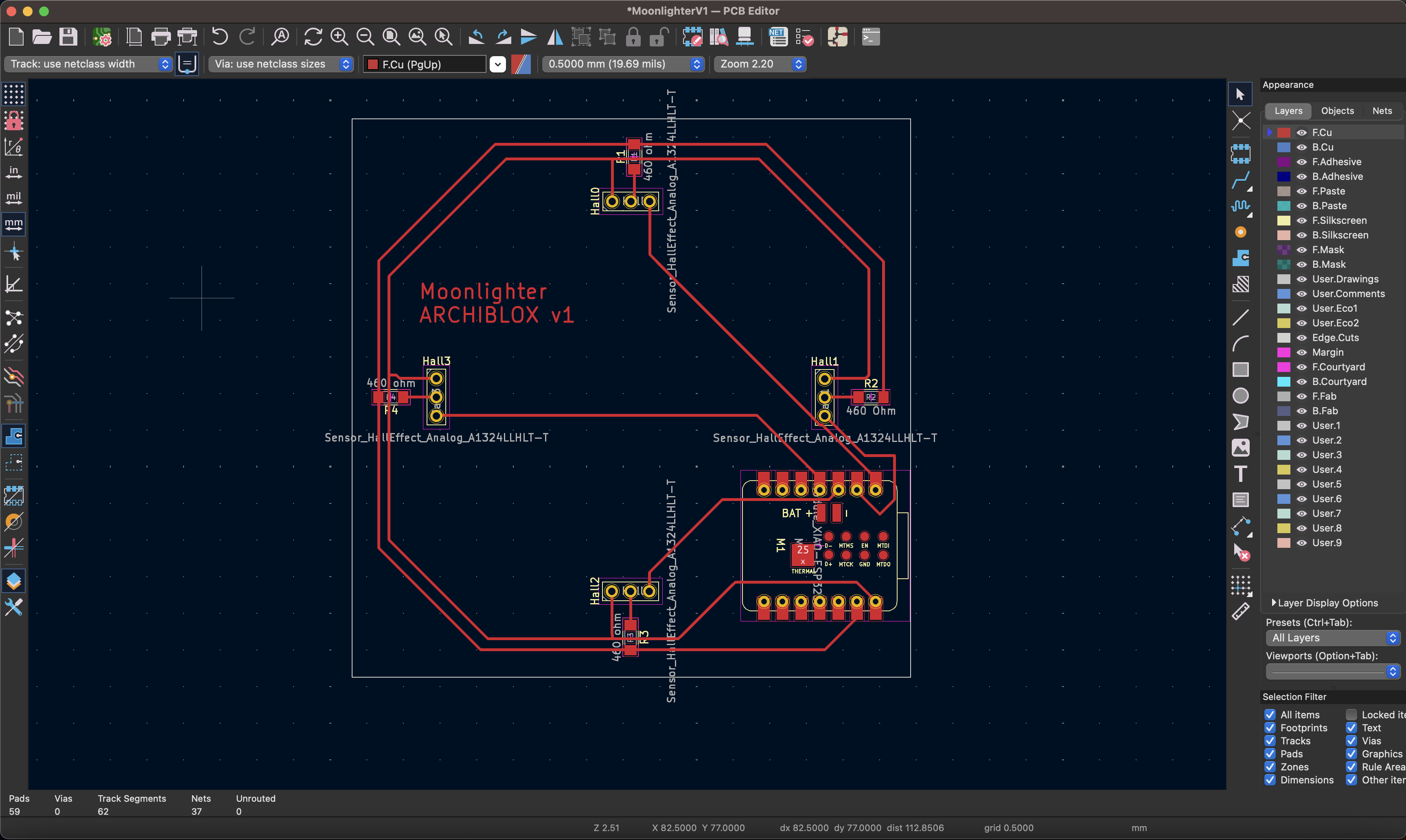
Open the PCB editor in KiCAD.
Import the schematic netlist to bring all components and connections into the PCB layout.
Place Components:
Arrange the ESP32-S3 and hall sensors on the PCB. Ensure there is enough space between components for routing.
Place the 0-ohm resistors strategically to bridge over the power trace.
Route the Traces:
Start by routing the power and ground traces. Design the traces so that all four sensors share the same power and ground trace. Ensure the power trace is wide enough to handle the current.
Route unique signal traces from each hall sensor to its corresponding GPIO pin on the ESP32-S3.
Use the 0-ohm resistors to jump over the power trace and complete the ground connections for each sensor.
Optimize Trace Layout:
Manually adjust the traces for efficiency and aesthetics. Ensure there are no sharp corners and that the traces have a smooth, logical flow.
Use vias if necessary to keep the layout clean, but since this is a single-sided PCB, try to minimize their use.
Step 3: Milling the PCB
Prepare the Design for Milling:
Export the PCB design to Gerber files.
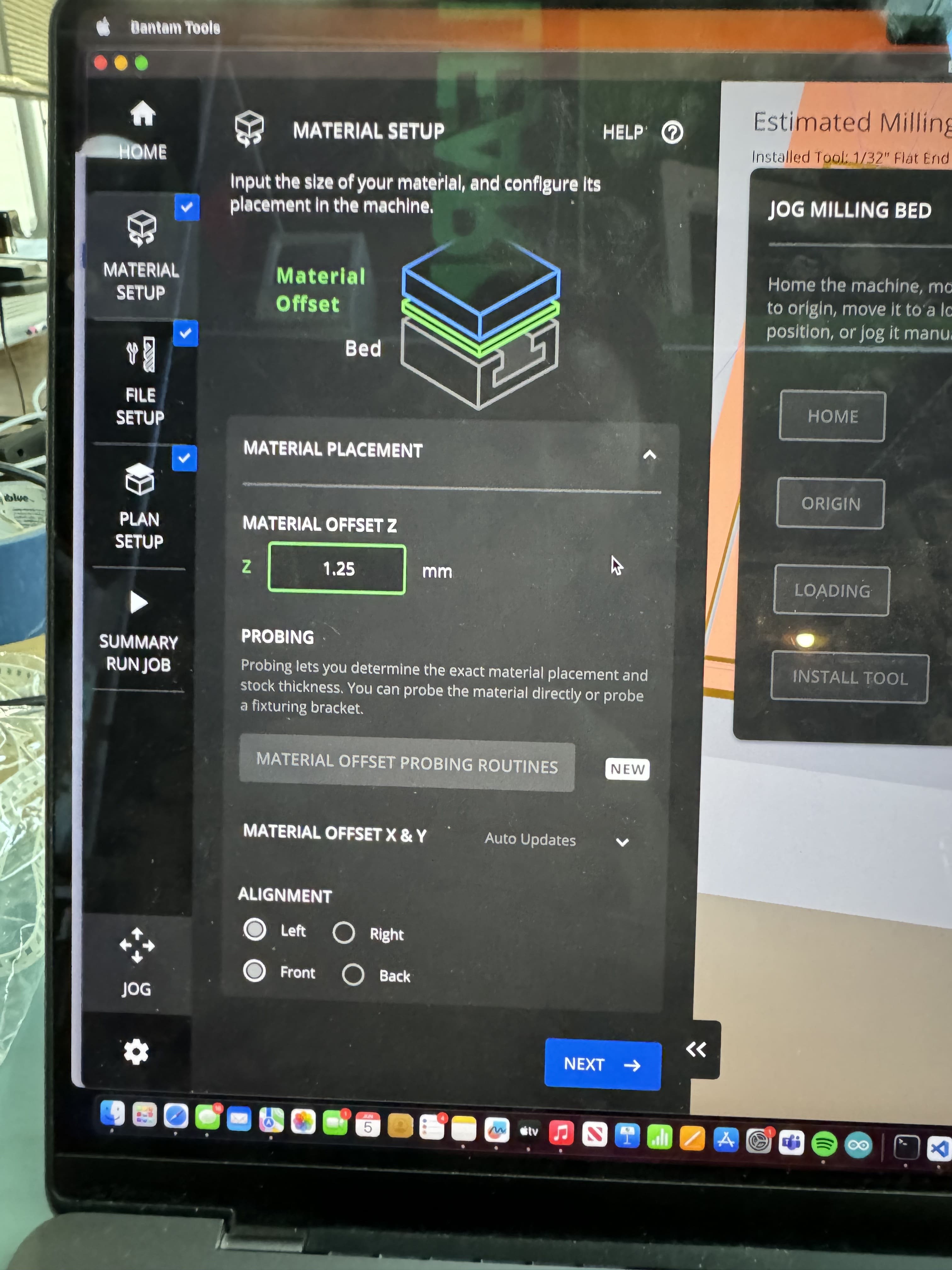
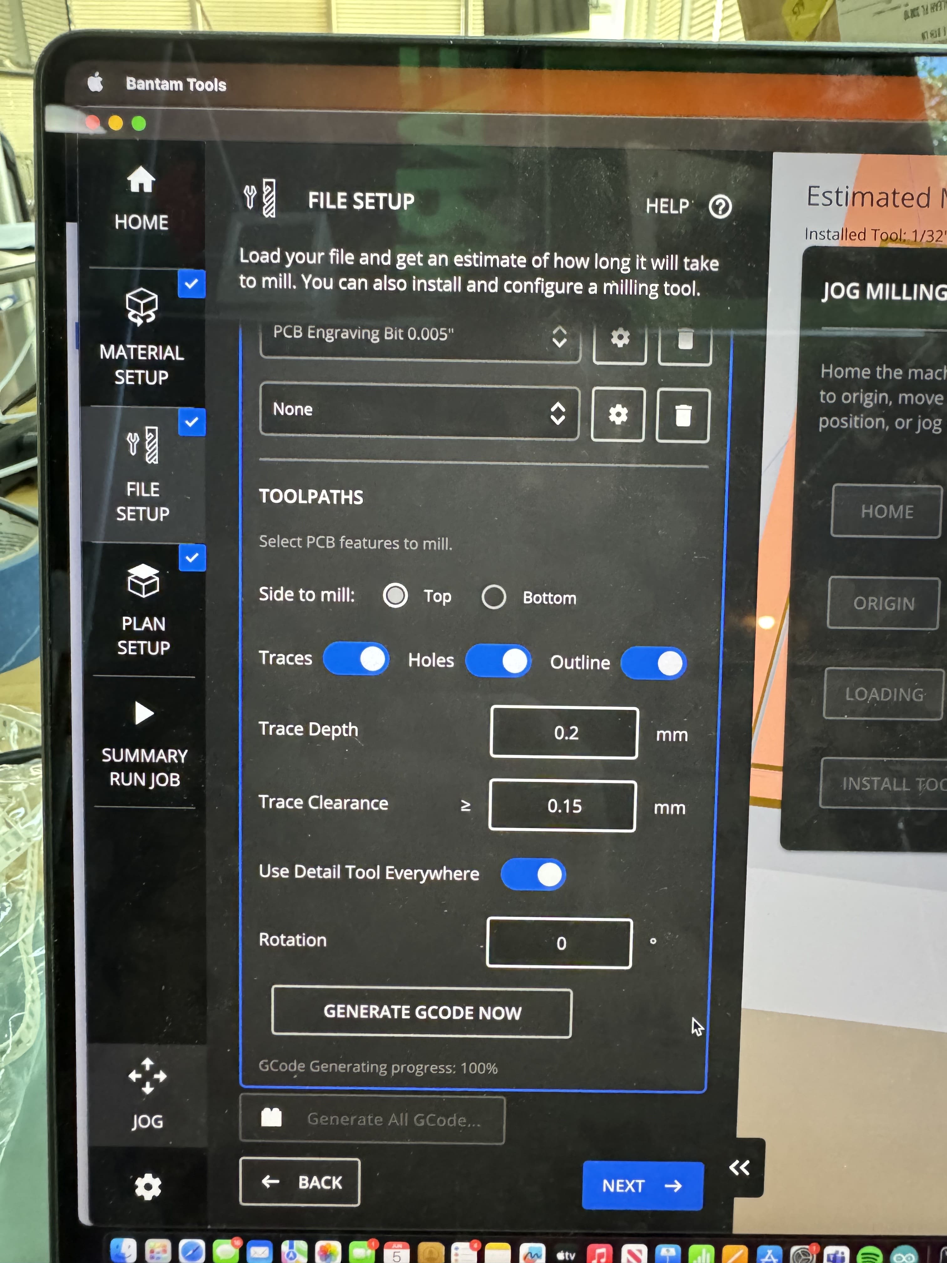
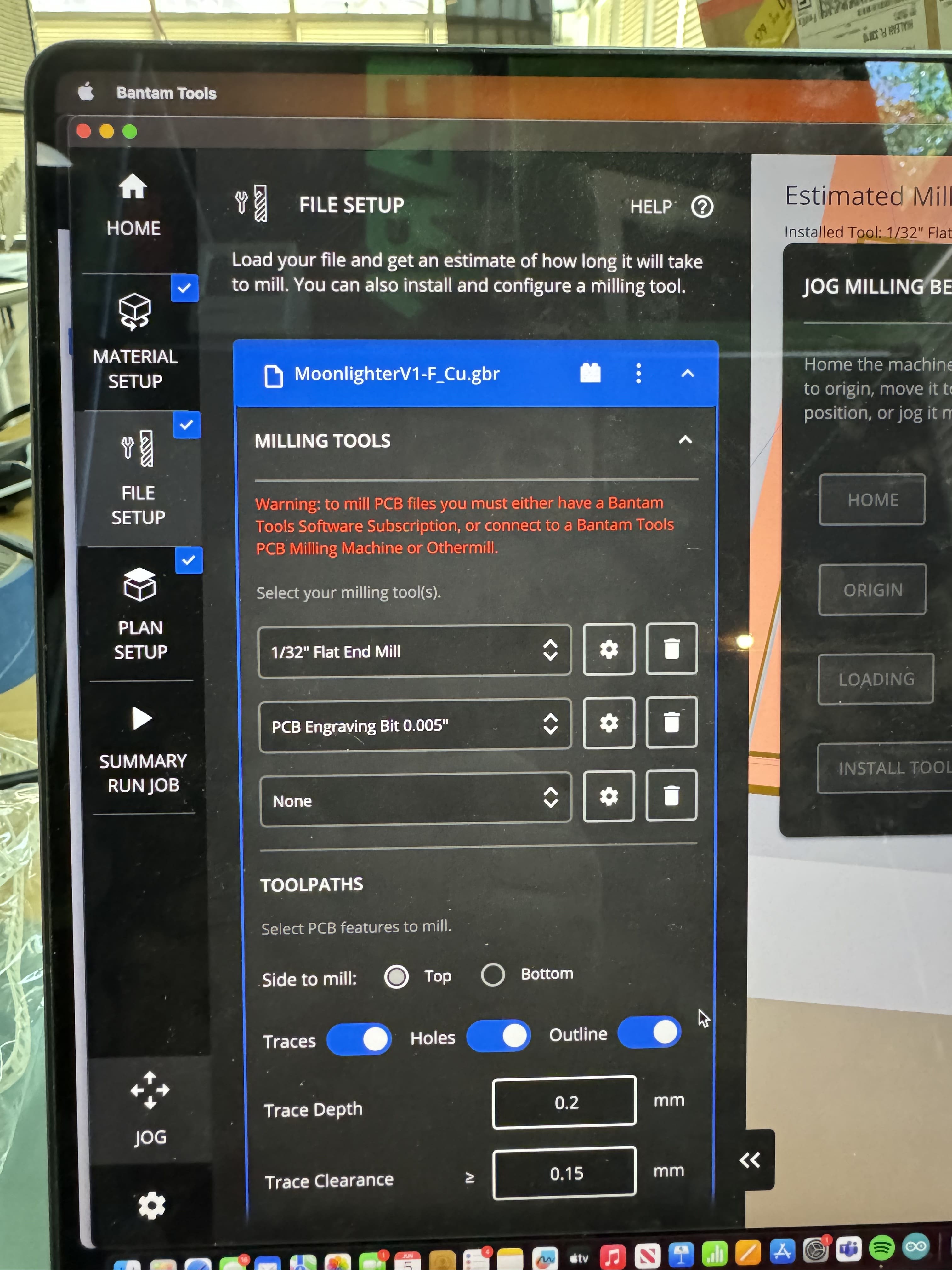
Import the Gerber files into the Bantam Tools CAM software.
Set Up Milling Parameters:
Use a .005 PCB engraving bit for detailed traces.
Use a 1/64" endmill for milling the traces, drilling through-holes, and cutting the board outline.
Optionally, add a 1/32" endmill to speed up the drilling and outline cutting process, reserving the smaller bits for intricate details.
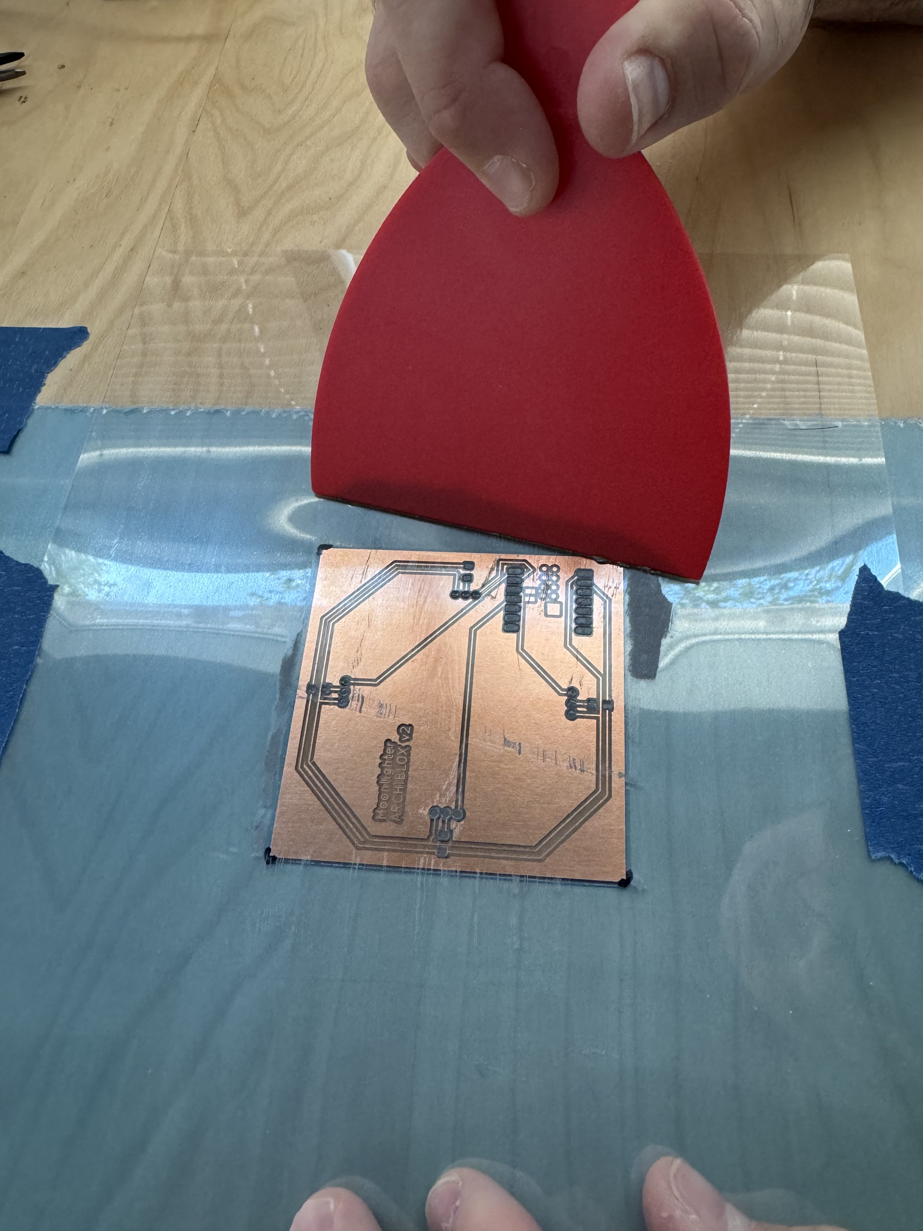
Mill the PCB:
Secure the PCB blank onto the Bantam Tools milling machine, (I used small squares of double stick tape!) Make sure you use a caliper to measure the tape thickness to add that to the material offset in the Bantam Tools CAM software.
Load the CAM software and start the milling process.
Monitor the milling to ensure accuracy and make any adjustments if needed.
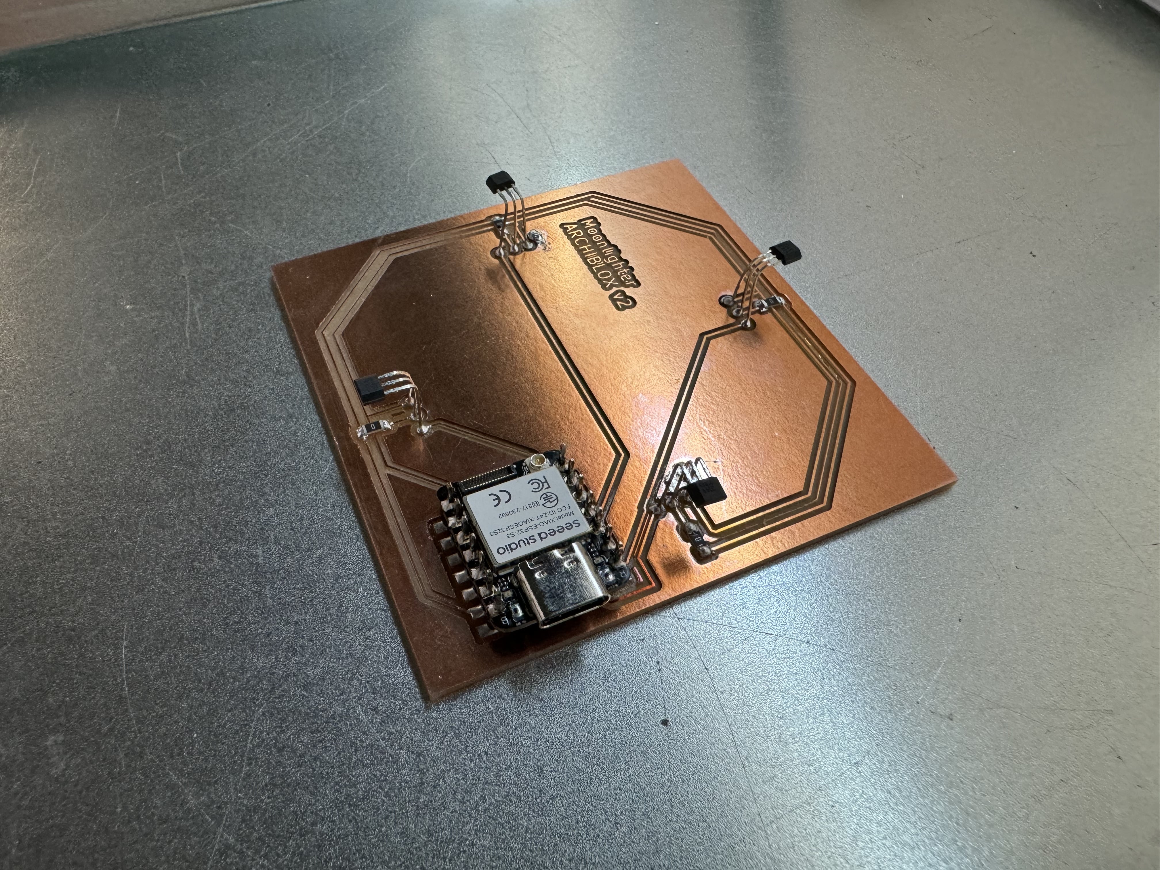
Circuit Production
Step 4: Programming the ESP32-S3
Program the ESP32-S3:
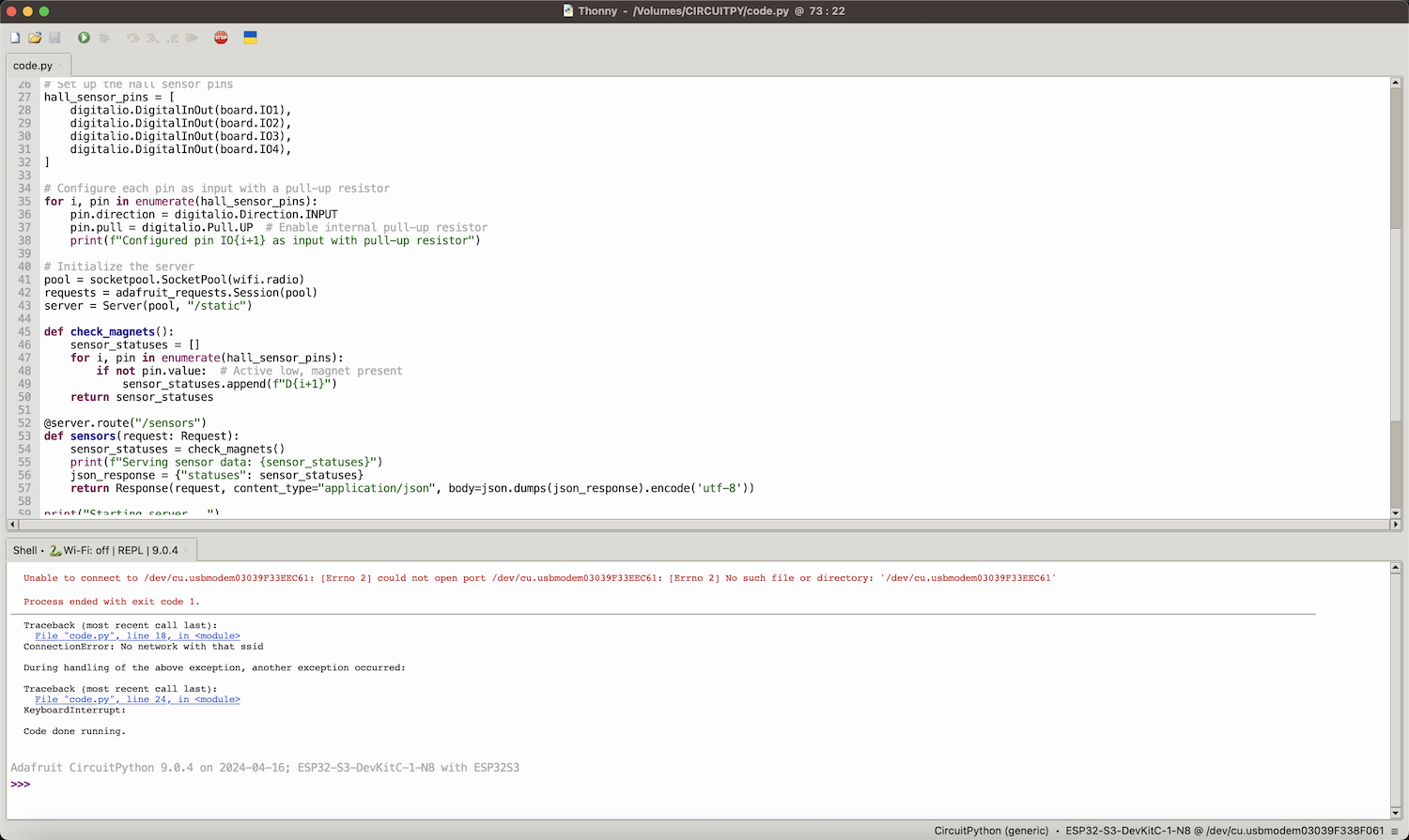
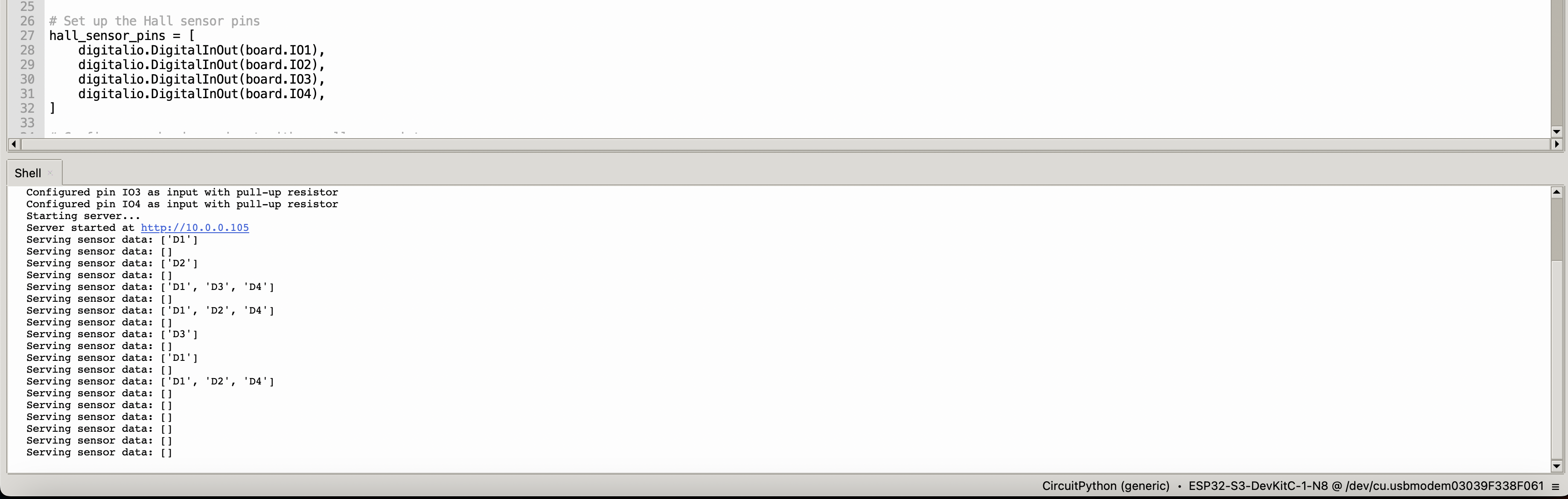
Use Thonny IDE to program the ESP32-S3 with CircuitPython.
Write a simple script to read data from the hall sensors and display the results.
To do this, I enlisted the help of ChatGPT by inputing in the prompt that I am programming an ESP32S3 using circuitpython. Write code that reads 4 hall sensors connected to 4 digital pins (D0, D1,D2,D3).
After a few attempts back and forth, this is the code that was created:
import board
import digitalio
import time
#Set up the Hall sensor pins
hall_sensor_pins = [digitalio.DigitalInOut(board.D0), digitalio.DigitalInOut(board.D1),
digitalio.DigitalInOut(board.D2), digitalio.DigitalInOut(board.D3)]
#Configure each pin as input with a pull-up resistor
for pin in hall_sensor_pins:
pin.direction = digitalio.Direction.INPUT
pin.pull = digitalio.Pull.UP # Enable internal pull-up resistor
def check_magnets():
sensor_statuses = []
for i, pin in enumerate(hall_sensor_pins):
if not pin.value:
sensor_statuses.append(f"Magnet detected on pin D{i}")
return sensor_statuses
while True:
statuses = check_magnets()
if statuses:
for status in statuses:
print(status)
else:
print("No magnet detected.")
time.sleep(1) # Check every 1 second
Test the Circuit:
Power up the ESP32-S3 and check the serial output to ensure the hall sensors are working correctly.
Move a magnet near each sensor and observe the corresponding output ("D0" for magnet 1, "D1" for magnet 2, "D2" for magnet 3, and "D3" for magnet 4).
Summary
By following these steps, I designed a PCB that efficiently connects four hall sensors to an ESP32-S3. The shared power and ground traces, unique signal traces, and use of 0-ohm resistors ensured a clean layout. Milling the PCB with the Bantam Tools machine and programming the ESP32-S3 in CircuitPython completed the process, allowing for successful sensor data acquisition.
Files
Download KiCAD Board Design Download CircuitPython Code
Group Assignment
When we wanted to test out the microcontroller on the QuenTorres boards, we decided to check a simple output: an LED, which we programmed to turn on and off. The LED is straightforward—it just follows the code to turn on and off. To test the LED with an oscilloscope, you start by placing one lead on the ground. The second lead goes where the LED connects, which on this board is the top left pin. When you observe the output, it jumps up to 3.3V and back down to zero, just like flipping a switch. This behavior is mirrored on the oscilloscope as well as the multimeter, with both showing the voltage rising and falling in sync with the LED turning on and off.
Multimeter Test
Oscilloscope Test
Copyright 2024 Thomas Pupo - Creative Commons Attribution Non Commercial
Source code hosted at fabcloud/fabacademy/2024/thomas-pupo