
Week 14: Networking & Communications
This Week's Goal
My board successfully identifies the hall sensors being triggered with the proximity of a magent and it can identify those magnets in the console. I now want the ESP32-S3 to use the wifi module to read those sensor inputs and display the vector image that corresponds to the sensor array.
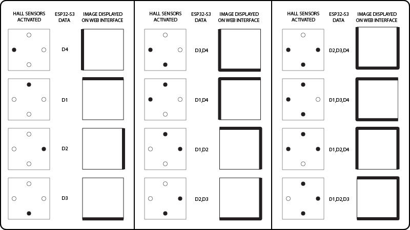
*All four magnets activated would trigger a thin outline tile with no walls to represent a floor-only tile.
Displaying Vector Images on Web Interface Based on Sensor Input Data
Building upon the work in the: Output Devices Week, I focused on getting the vector png images to display on a web interface generated by the ESP32S3 wifi module.
I once again utilized the help of ChatGPT to help create the basic code framework to make it work.
Here's what it suggested:
Set up the web server on ESP32-S3:
Modify your existing code to serve the sensor data via a web server.
Use the MicroWebSrv2 library to handle HTTP requests and serve static files (your HTML, CSS, and JavaScript files).
Create the frontend:
Use HTML to structure your page.
Use CSS to style the page.
Use JavaScript to fetch the sensor data from the ESP32-S3 and update the visualization in real-time.
Making the ESP32-S3 Wirelessly Communicate with a Web Site
Step 1: ESP32-S3 Web Server Code
First, install the required libraries for the ESP32-S3:
pip install adafruit-circuitpython-wifi adafruit-circuitpython-digitalio adafruit-circuitpython-busdevice microdot
Then, modify the code as follows:
import board
import digitalio
import time
import wifi
import socketpool
from microdot import Microdot, Response
# WiFi Configuration
SSID = "******" # Replace with your WiFi SSID
PASSWORD = "******" # Replace with your WiFi password
# Connect to WiFi
print("Starting WiFi connection process...")
try:
print(f"Attempting to connect to SSID: {SSID}")
wifi.radio.connect(SSID, PASSWORD)
print("Connected to WiFi")
print(f"IP Address: {wifi.radio.ipv4_address}")
except ConnectionError as e:
print(f"Failed to connect to WiFi: {e}")
while True:
pass # Halt execution if WiFi connection fails
# Set up the Hall sensor pins
hall_sensor_pins = [
digitalio.DigitalInOut(board.IO0),
digitalio.DigitalInOut(board.IO1),
digitalio.DigitalInOut(board.IO2),
digitalio.DigitalInOut(board.IO3),
]
# Configure each pin as input with a pull-up resistor
for i, pin in enumerate(hall_sensor_pins):
pin.direction = digitalio.Direction.INPUT
pin.pull = digitalio.Pull.UP # Enable internal pull-up resistor
print(f"Configured pin IO{i} as input with pull-up resistor")
app = Microdot()
@app.route('/')
def index(request):
return Response('
ESP32-S3 Sensor Data
')@app.route('/sensors')
def sensors(request):
sensor_statuses = check_magnets()
return {'statuses': sensor_statuses}
def check_magnets():
sensor_statuses = []
for i, pin in enumerate(hall_sensor_pins):
if not pin.value:
sensor_statuses.append(f"D{i}")
return sensor_statuses
if __name__ == '__main__':
app.run(port=80)
Step 2: Create the Frontend
Create a main.js file to handle fetching the sensor data and updating the visualization:
setInterval(async () => {
const response = await fetch('/sensors');
const data = await response.json();
const statuses = data.statuses;
drawBoxWithLines(statuses);
}, 1000);
function drawBoxWithLines(sensorStatuses) {
const box = Array.from({ length: 10 }, () => Array(10).fill(' '));
let drawTop = false;
let drawLeft = false;
let drawRight = false;
let drawBottom = false;
// Check for specific combinations first
if (sensorStatuses.includes("D0") && sensorStatuses.includes("D1") && sensorStatuses.includes("D3")) {
drawTop = true;
drawLeft = true;
drawRight = true;
} else if (sensorStatuses.includes("D0") && sensorStatuses.includes("D1") && sensorStatuses.includes("D2")) {
drawTop = true;
drawRight = true;
drawBottom = true;
} else if (sensorStatuses.includes("D1") && sensorStatuses.includes("D2") && sensorStatuses.includes("D3")) {
drawLeft = true;
drawRight = true;
drawBottom = true;
} else if (sensorStatuses.includes("D0") && sensorStatuses.includes("D2") && sensorStatuses.includes("D3")) {
drawTop = true;
drawLeft = true;
drawBottom = true;
} else if (sensorStatuses.includes("D0") && sensorStatuses.includes("D1") && sensorStatuses.includes("D2") && sensorStatuses.includes("D3")) {
drawTop = true;
drawLeft = true;
drawRight = true;
drawBottom = true;
} else if (sensorStatuses.includes("D0") && sensorStatuses.includes("D1")) {
drawTop = true;
drawRight = true;
} else if (sensorStatuses.includes("D1") && sensorStatuses.includes("D2")) {
drawRight = true;
drawBottom = true;
} else if (sensorStatuses.includes("D2") && sensorStatuses.includes("D3")) {
drawLeft = true;
drawBottom = true;
} else {
sensorStatuses.forEach(status => {
if (status === "D0") drawTop = true;
if (status === "D1") drawRight = true;
if (status === "D2") drawBottom = true;
if (status === "D3") drawLeft = true;
});
}
if (drawTop) {
for (let i = 0; i < 10; i++) box[0][i] = "-";
}
if (drawRight) {
for (let i = 0; i < 10; i++) box[i][9] = "|";
}
if (drawBottom) {
for (let i = 0; i < 10; i++) box[9][i] = "-";
}
if (drawLeft) {
for (let i = 0; i < 10; i++) box[i][0] = "|";
}
const boxElement = document.getElementById('box');
boxElement.innerHTML = '';
box.forEach(row => {
const rowDiv = document.createElement('div');
rowDiv.textContent = row.join('');
boxElement.appendChild(rowDiv);
});
}
Place the main.js file in the same directory as the Python script. When you run the Python script on the ESP32-S3, it will start a web server. You can then access the web page by navigating to the IP address of the ESP32-S3 in your browser. The page will fetch the sensor data every second and update the visualization accordingly.
Troubleshooting Various Issues
I was then having an error:
>>> %Run -c $EDITOR_CONTENT
Traceback (most recent call last):
File "
ImportError: no module named 'microdot'
>>>
When I inquired about this to ChatGPT it provided the following update:
It looks like the microdot library is not installed or not available. Since microdot is a lightweight web server designed for microcontrollers, you can use it if it's available for your platform. If not, another approach is to use the uasyncio and uwebsocket libraries provided by MicroPython, which are more commonly supported on microcontrollers.
Here's how to implement a web server using uasyncio and microdot_asyncio:
Install necessary libraries:
If using MicroPython, you will need to ensure uasyncio and microdot_asyncio are available.
Modify the ESP32-S3 code to use uasyncio and microdot_asyncio.
index.html File
Place index.html file in a directory named static on your CircuitPython device
Explanation
WiFi Connection: The script attempts to connect to the WiFi network with the specified SSID and password. If it fails, it prints an error message and halts execution.
Hall Sensor Pins Setup: Configures the hall sensor pins as inputs with internal pull-up resistors.
Web Server Setup: Uses adafruit_httpserver to serve the index.html file and provide a JSON endpoint /sensors that returns the status of the hall sensors.
Error Handling: Includes error handling for both WiFi connection and server start failures. If an error occurs, it prints the error message and halts execution.
When you run the modified Python script on the ESP32-S3, it will start a web server and serve the index.html file. You can access the web page by navigating to the IP address of the ESP32-S3 in your browser. The page will fetch the sensor data every second and update the visualization accordingly.
To browse to your ESP32-S3 web server from your computer, follow these steps:
Run the Python Script on Your ESP32-S3:
Ensure that the Python script provided above is running on your ESP32-S3. This script will connect the ESP32-S3 to your WiFi network and start a web server.
Find the IP Address of the ESP32-S3:
When the ESP32-S3 successfully connects to your WiFi network, it will print its IP address to the serial console. Look for a line like this in the serial console output:
Open a Web Browser on Your Computer:
Open your preferred web browser (e.g., Chrome, Firefox, Safari).
Navigate to the IP Address of the ESP32-S3:
In the address bar of the web browser, type the IP address of your ESP32-S3 that you found in step 2, and press Enter. The address should look something like this:
View the Web Page:
You should see the web page served by your ESP32-S3. This page will fetch the sensor data every second and update the visualization accordingly.
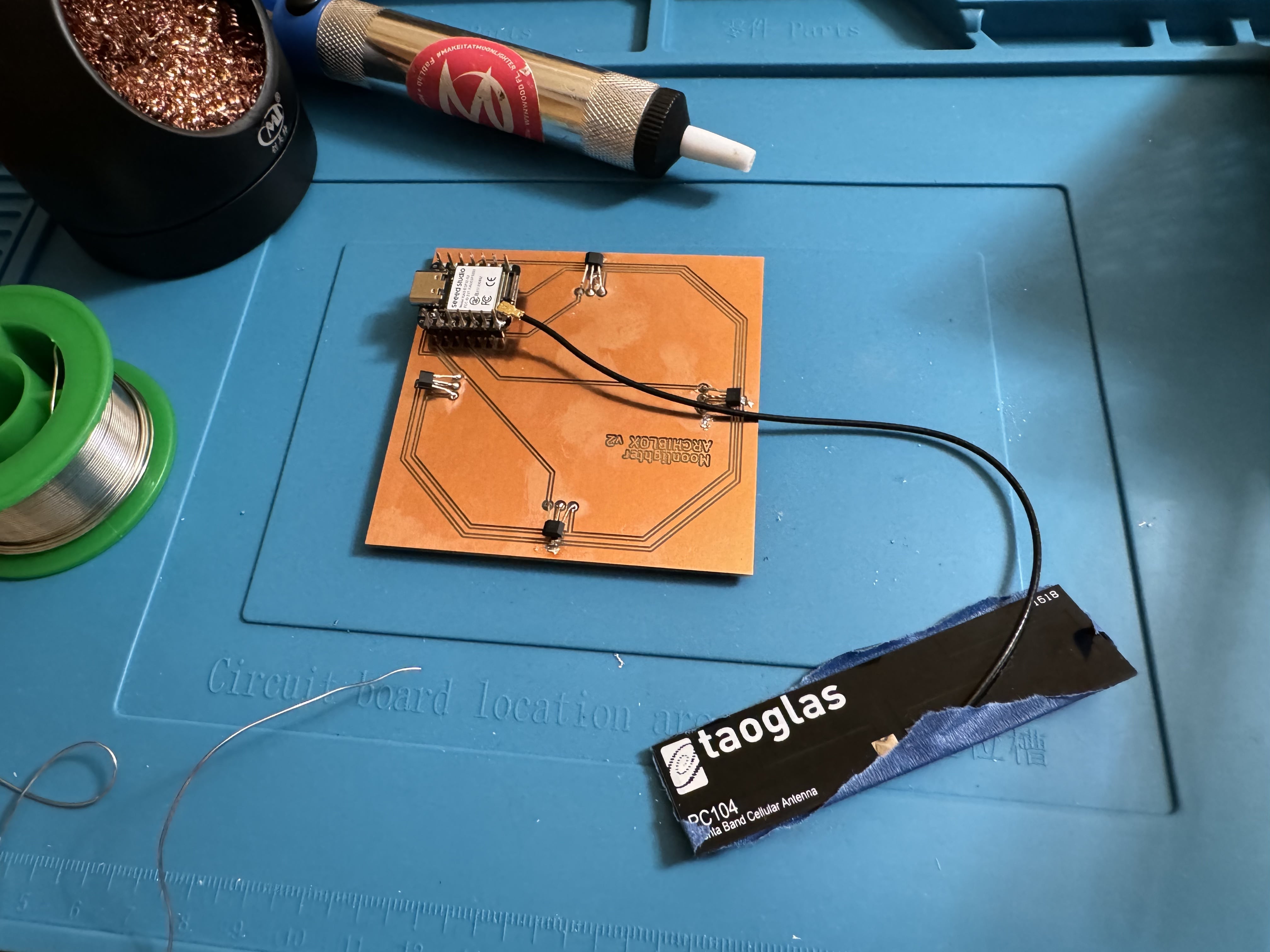
Upgrading the Antannae
I was having issues connecting and it was spotty, what I realised was that the tiny antennae that came with the ESP32-S3 was not creating a stable connection, so I swapped it out for a bigger anntenae and the the connection was much better.
Caching the Images for Faster Load Time
The next issue was that there was a delay in loading up the vector images on the web interface.
The workaround was to have the code immediately cache all the images on the browser so once you placed a tile on the Hall Sensors the image would populate instantly.
For the test, I added a 1/8" basswood between the hall sensors and the magnets in the tile to make sure that all of the connections would work when fully encased in the final product. It was a success:
Final Communications Test
Files
Download Code
Copyright 2024 Thomas Pupo - Creative Commons Attribution Non Commercial
Source code hosted at fabcloud/fabacademy/2024/thomas-pupo