Embedded Programming
This week, I learned embedded programming.wow ! it felt like deciphering an ancient script, with everything being new acquaintances. After going through a lot of materials, I finally gained some understanding of the programming architecture. In the end, I achieved a little interaction and communication, and it feels really rewarding!
1.1 Assignments of the Week
- Group assignment:
Browse through the datasheet for your microcontroller
Compare the performance and development workflows for other architectures
- Individual assignment:
Write a program for a microcontroller development board to interact (with local input &/or output devices) and communicate (with remote wired or wireless devices)

1.2 Group Work
We tried to use Arduino Uno, Mirco-Bit...... Here is the documentation.
1.3 Individual Work
The individual assignment requires using microcontroller development boards to write programs for interact and communicate.It's really fascinating!
1.3.1 interact (with local input &/or output devices)
- (1) Microbit
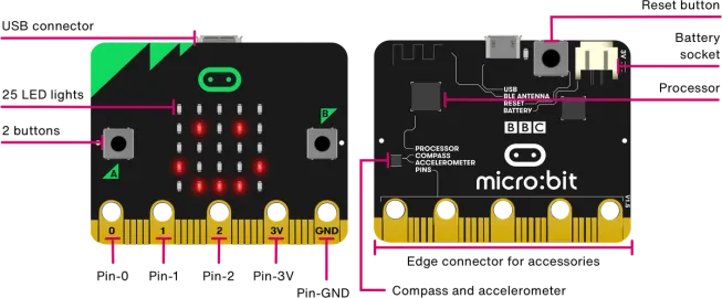
I want to create a 123 numbers melody using the three digital pins and the 5x5 LED matrix on microbit. The desired outcome is that when I touch a pin, the corresponding number LED should light up. Let's work on this together!
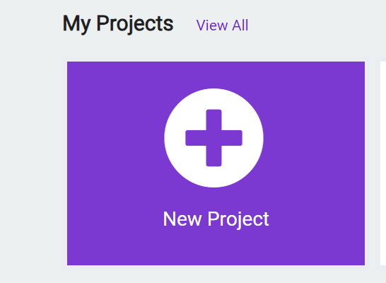
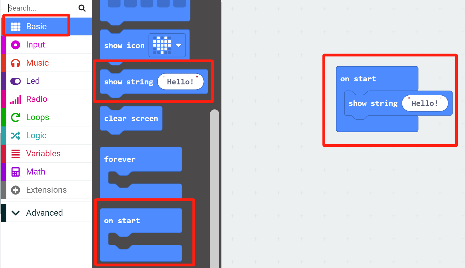
1.Open the web version of MakeCode, and a delightful and charming interface will appear. Begin a new project.

2.Basic—On start—Show string"Hello!"
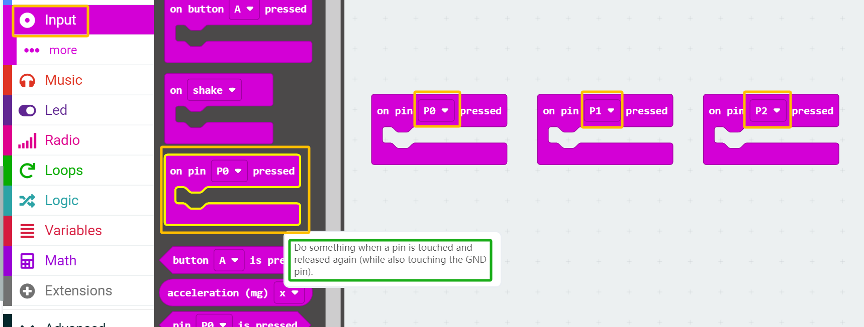
3.Input—On pin(Pin)pressed,when a pin is touched and released again(while also touching the GND pin).
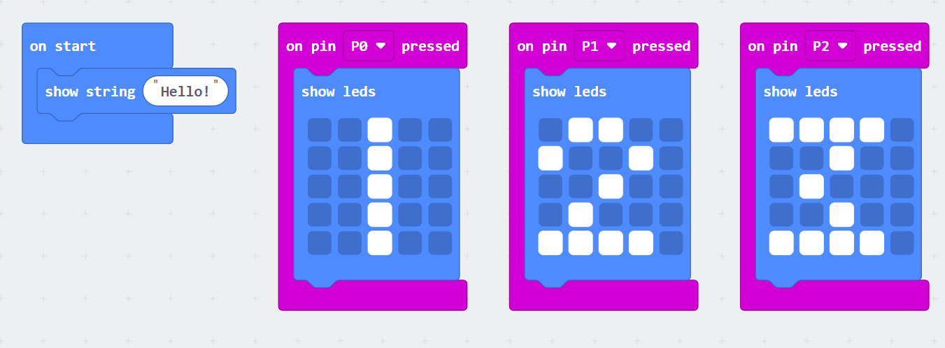
4.Basic—show leds,click on the block to set the LED positions.

5.This is the complete code block. You can test it online in the web browser. It works perfectly and achieves the desired effect!
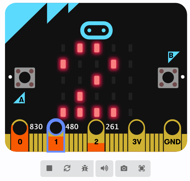
6.Click on download and select your connected device.

Look!
- (2) Seeed XIAO RP2040
Utilizing the pre-mill PCB board, create an input-output interactive device with the buttons(GPIO Pin 27) and three small LEDs(GPIO Pin 27/0/1). The basic idea is to press the button (high-level signal), and three small LEDs sequentially light up at a speed of 0.5 seconds, then return to the low-level signal.

Configure button and LED pins based on the pin diagram above. Set the button as input and the LED as output. Use IF statements to control the states of high and low levels.
Coding-Wire Sample code:

Look!
1.3.2 Serial Communication
-
(1) Seeed XIAO RP2040 and computer communication
I did inter-board communication for the first time, so I first learned about serial communication between boards and computers. In the Arduino IDE, I connected the Seeed XIAO RP2040 development board and implemented two simple communications.
1.Through the serial port, it sends the string "Hi! Juliet" once per second. When you connect Arduino to the computer and open the Serial Monitor in the Arduino IDE, you can see the "Hi! Juliet" string scrolling automatically every second.

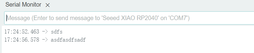
2.In the advanced version below, send data to Arduino through the Serial Monitor, and you should see the same data being sent back in the monitor. This type of program is very useful for debugging serial communication (testing if serial communication is working properly).