Electronics Production
This week, we will practice the PCB production process, manufacture and test microcontrollers, which also involves soldering. It's going to be a fun week!
1.1 Assignments of the Week
Group assignment:
-
Characterize the design rules for your in-house PCB production process: document feeds, speeds, plunge rate, depth of cut (traces and outline) and tooling.
-
Document the workflow for sending a PCB to a board house
-
Document your work to the group work page and reflect on your individual page what you learned
Individual Assignment:
- Make and test a microcontroller development board

1.2 Group Assignment
1.2 Individual Assignment
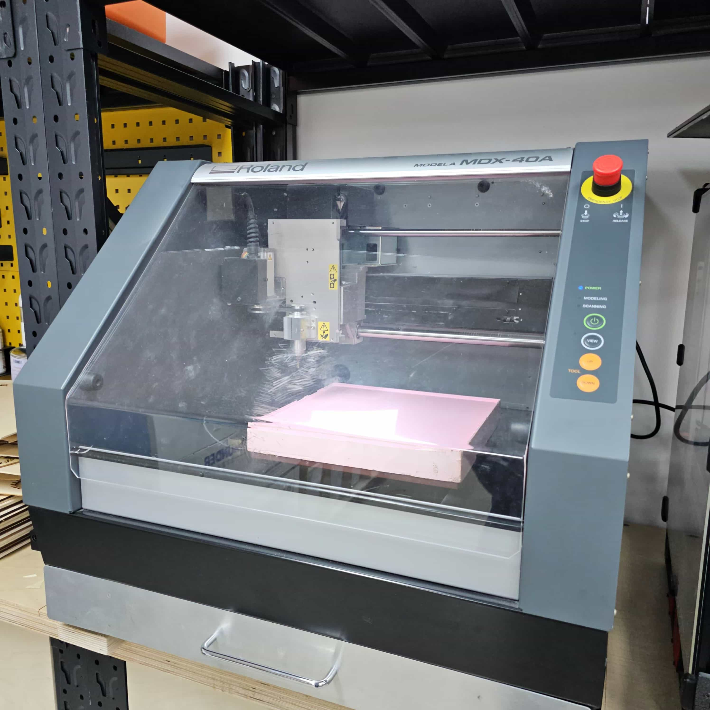
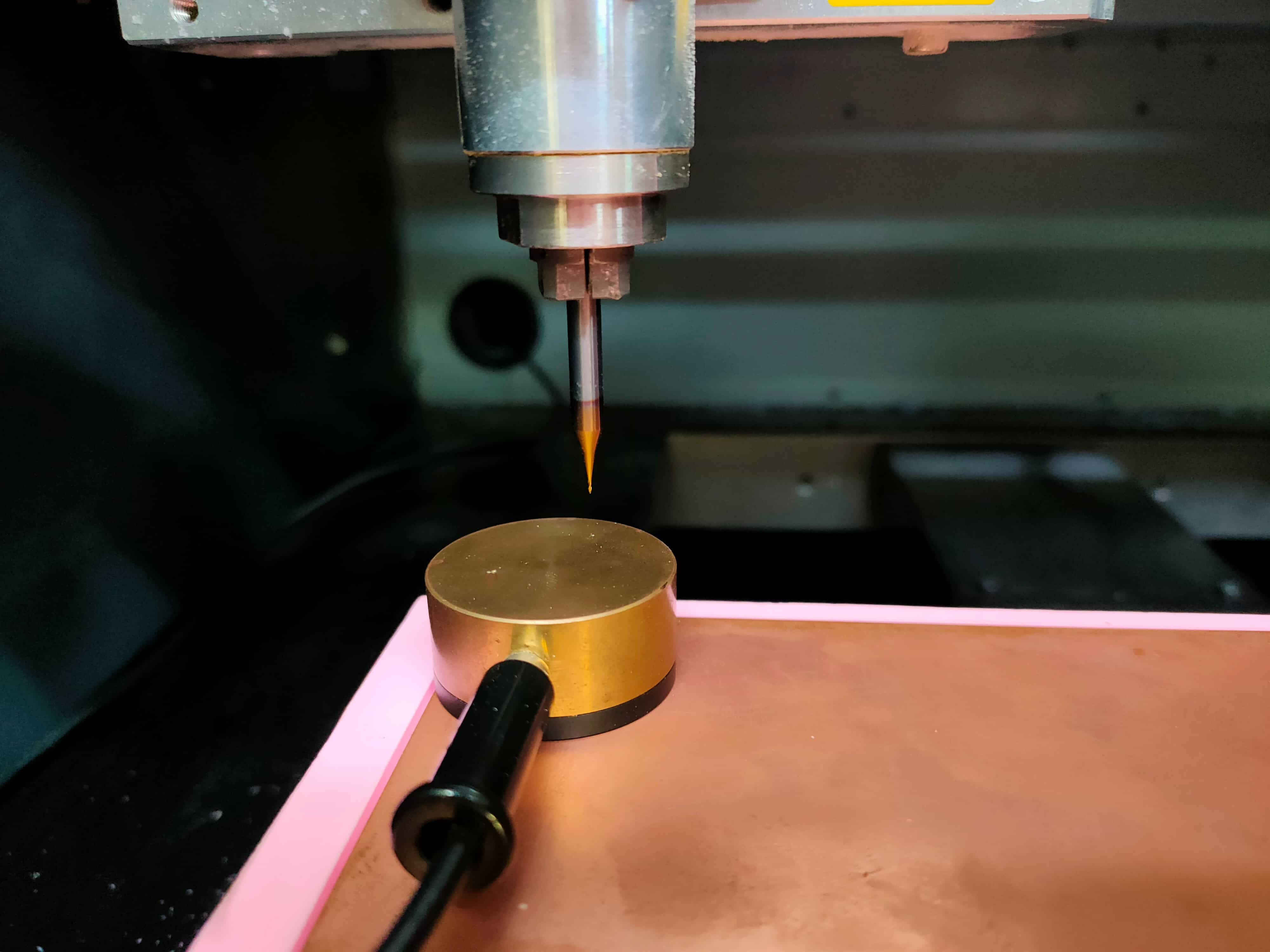
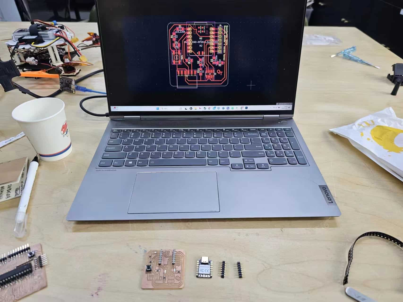
The CNC model I used is as follows:
1.2.1 Making the PNG files
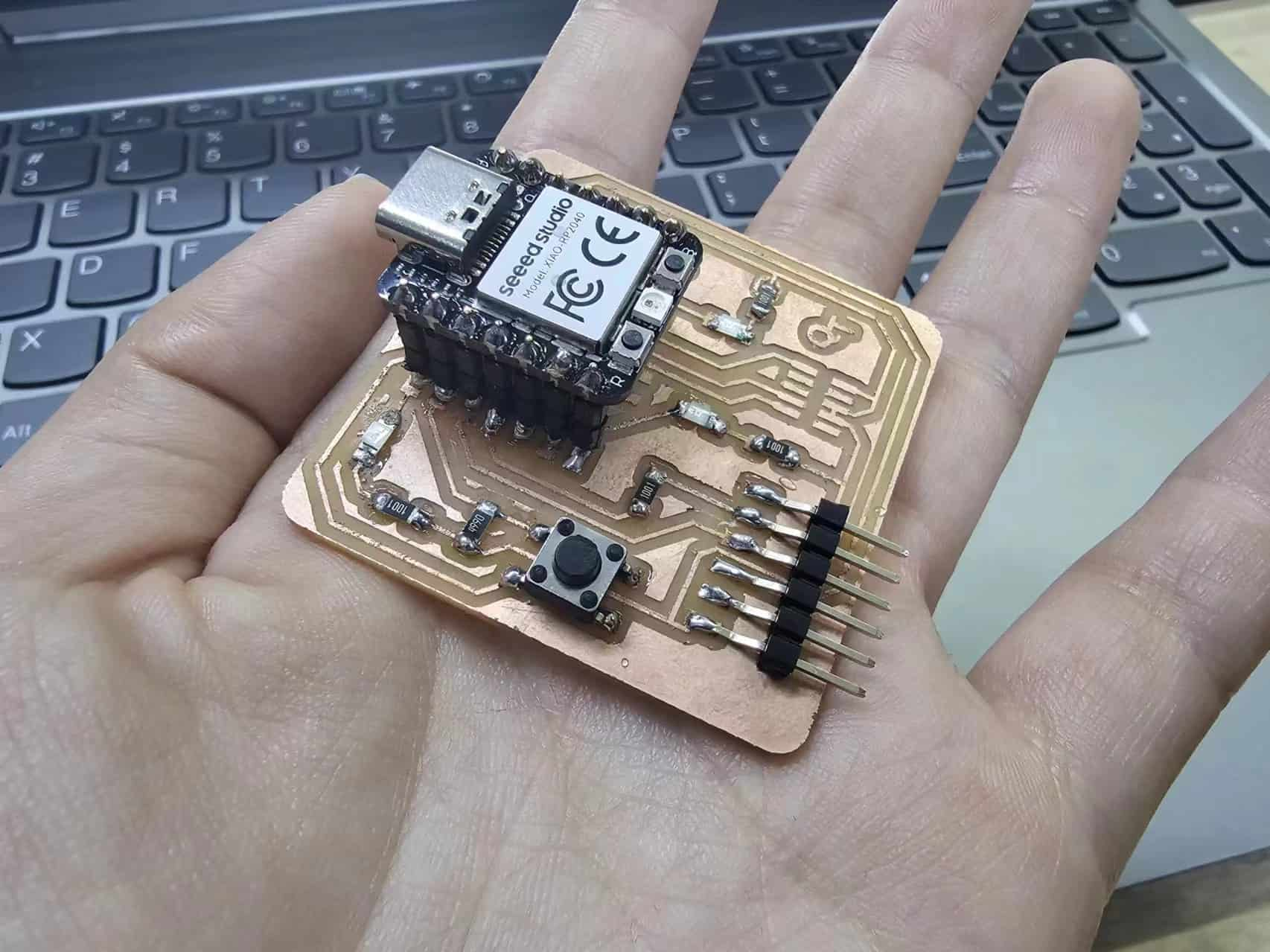
Since I have never made a PCB, I downloaded the milling source file from the example shared by Adrián Torres.Combining the test results of the group assignment,I made this circuit board.
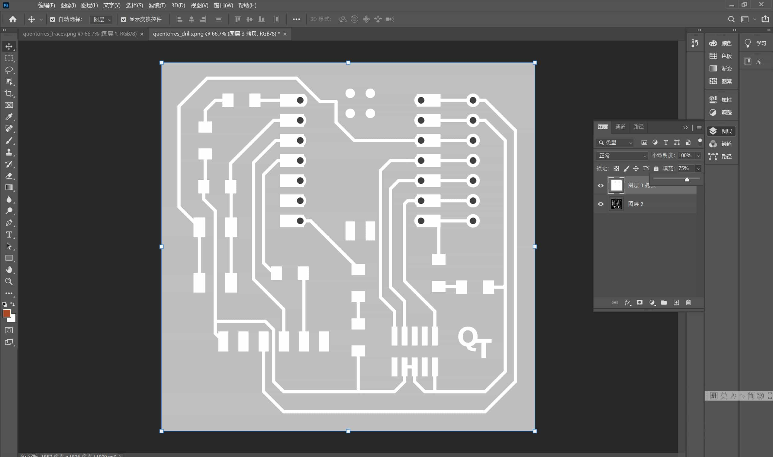
These are the original three files. Here, the milled holes only leave the hole positions for seven single-row round-hole female headers. The middle connection XIAO RP2040 leaves the position for surface mount welding. Considering that direct welding is not easy to reuse, I used Photoshop to add two rows of single-row round-hole female headers in the surface mount position. I went to the official website to query the pin distance of XIAO RP2040, which is the commonly used pitch of 2.54mm. The pin pitch and number are the same as those drawn by the author. So I copied two rows and moved them to the surface mount position.
Photoshop modification
This is the drills after adding two rows of single-hole female headers. It looks quite good. Then export the file to PNG format.
1.2.2 Tool path greneration-Modsproject
In class, I saw Neil mention this path generation website. My smart colleague will learn it soon, and then he taught me how to use it.
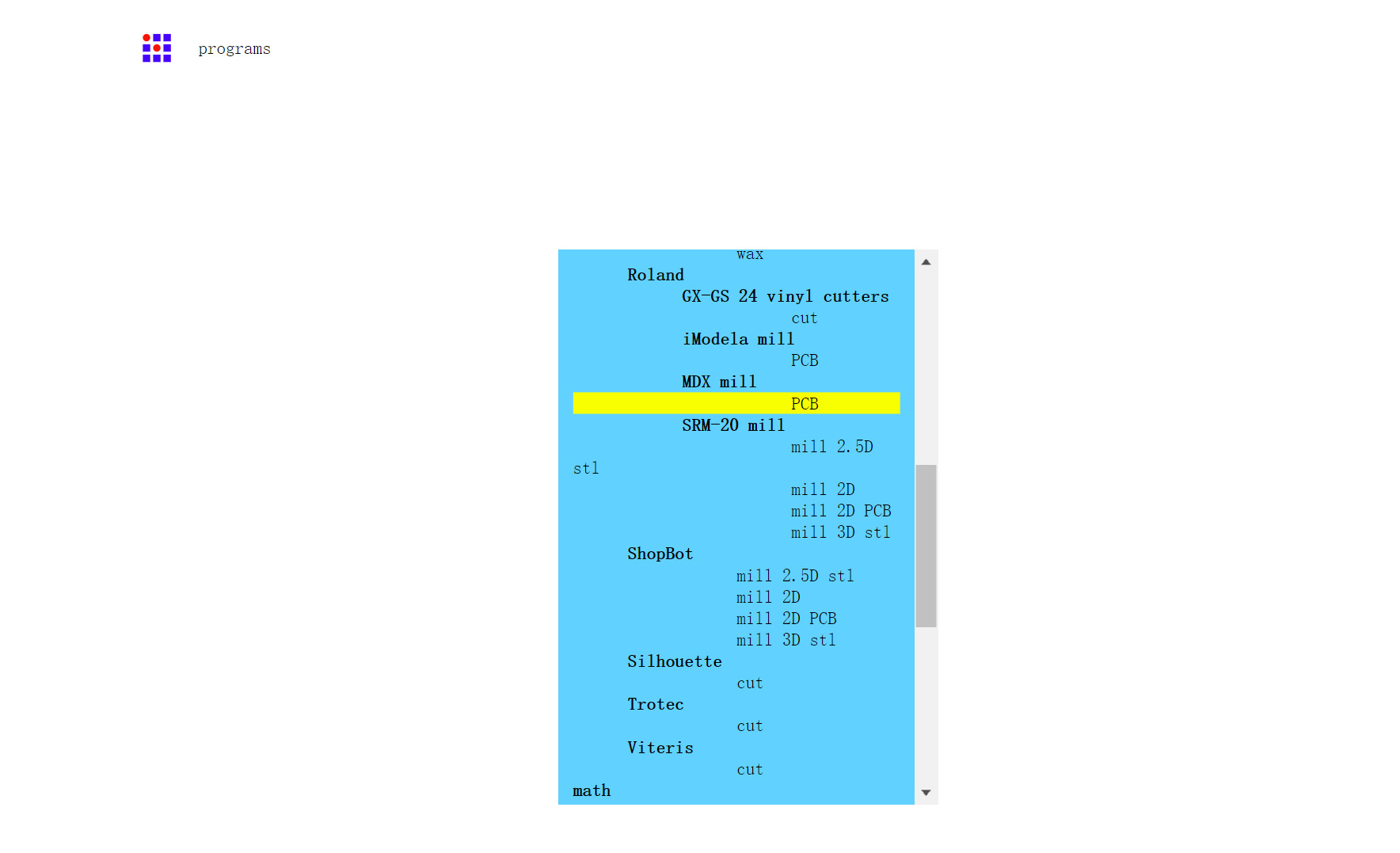
First, I searched for mods projects on Google. After entering, right-clicking will pop up some options. Follow this order (programs-open program-Roland-MDX mill-PCB) to enter the path setting

From here on, there are some very delicate and important settings. Any wrong one may cause problems with the milling file.
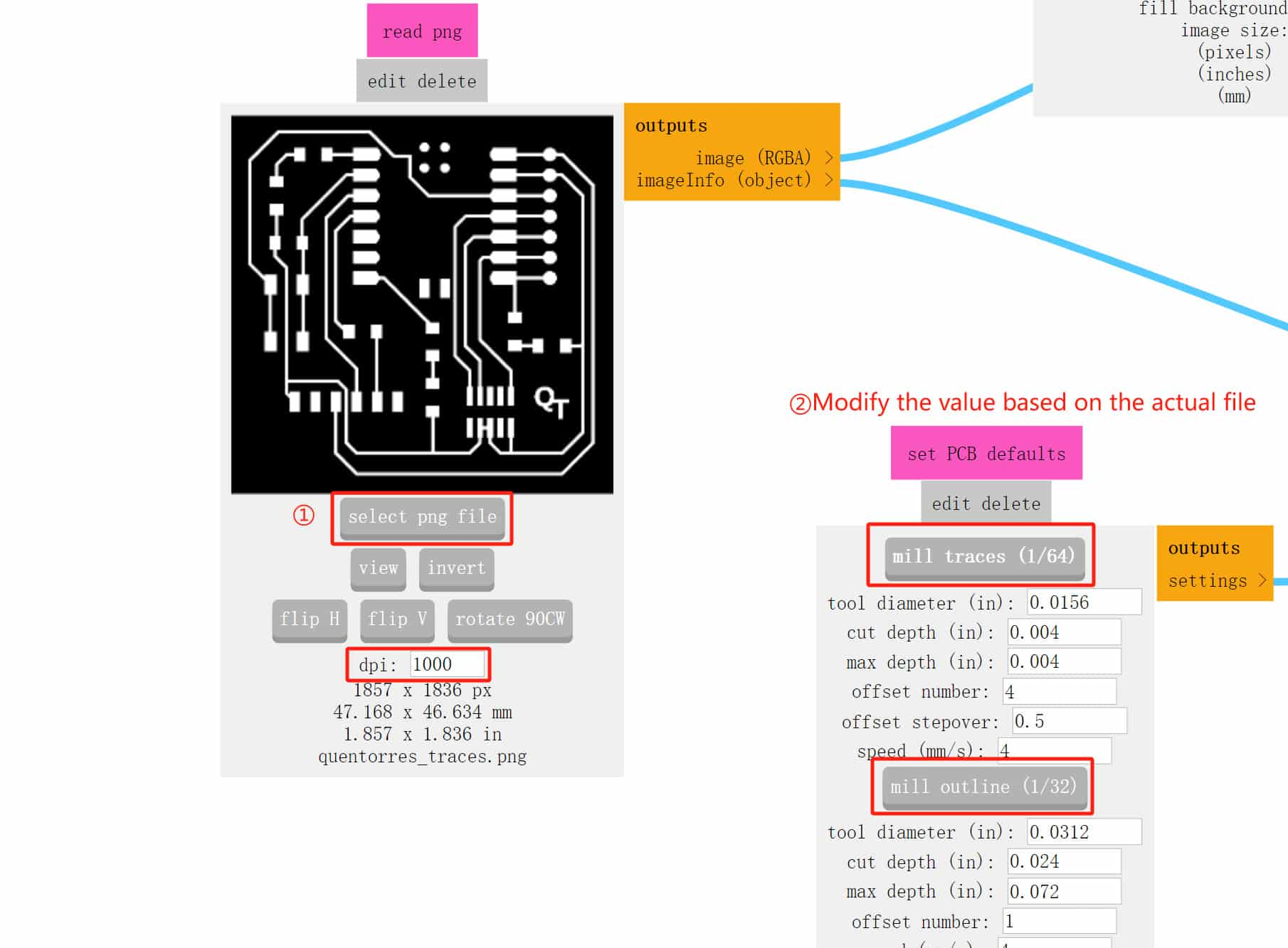
Step 1: import the png files downloaded before, change the dpi of each picture to 1000, keep it consistent with photoshop, otherwise there will be problems with the milling size. After the modification, there will be a size below for review
There are two types here, end mill and v-bit.
I checked the difference between the two types of milling cutters.Endmill is usually cylindrical in shape, and its end can be flat or have a certain curvature. For some engraving effects with special angle requirements, the end mill may not be able to achieve it directly. The V-shaped milling cutter will leave obvious V-shaped marks on the surface after processing. In engraving applications, this mark can enhance the three-dimensional and layered sense of the engraved pattern. However, if it is used for non-engraving purposes such as plane milling, the surface flatness after processing may not be as good as that of the end mill.

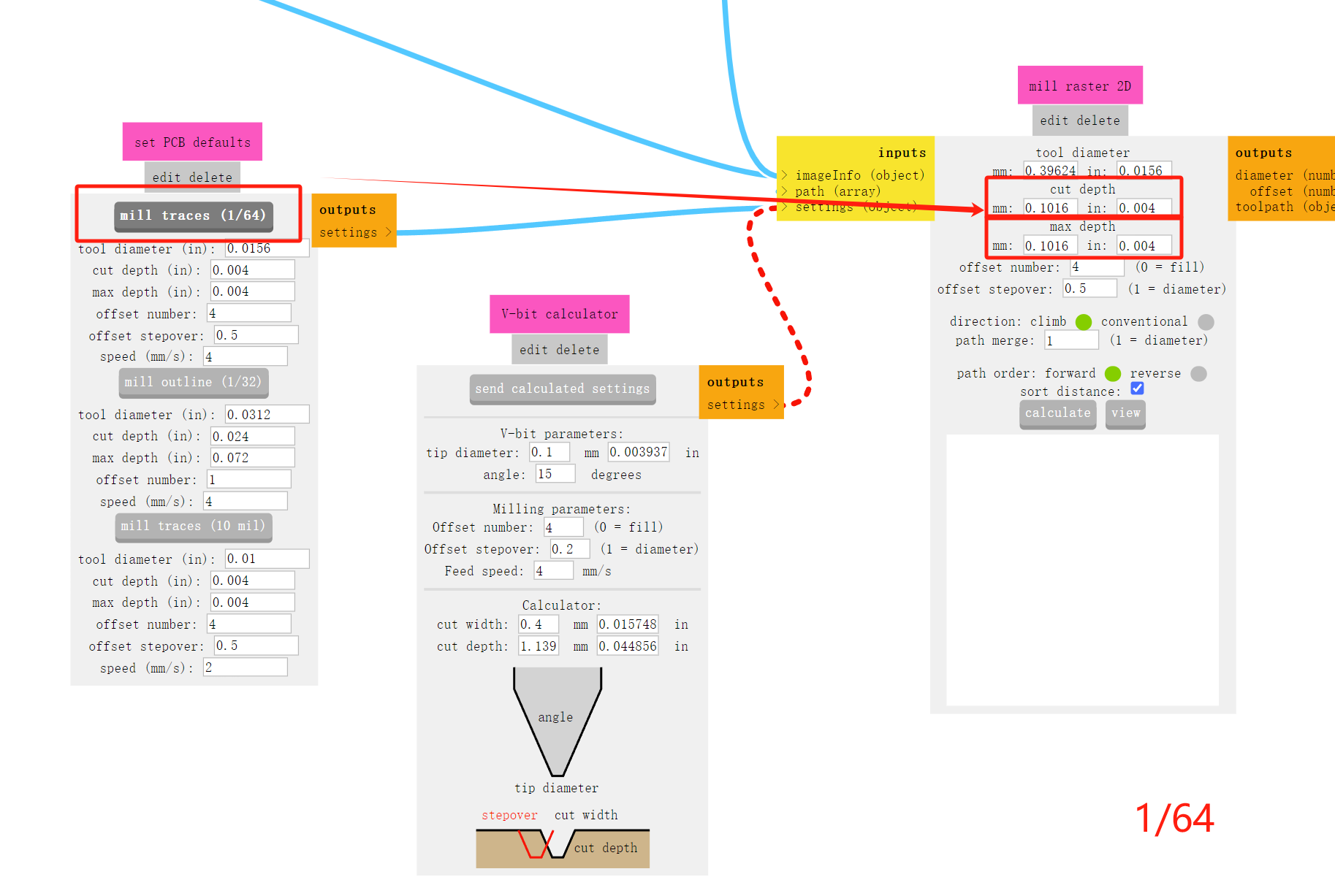
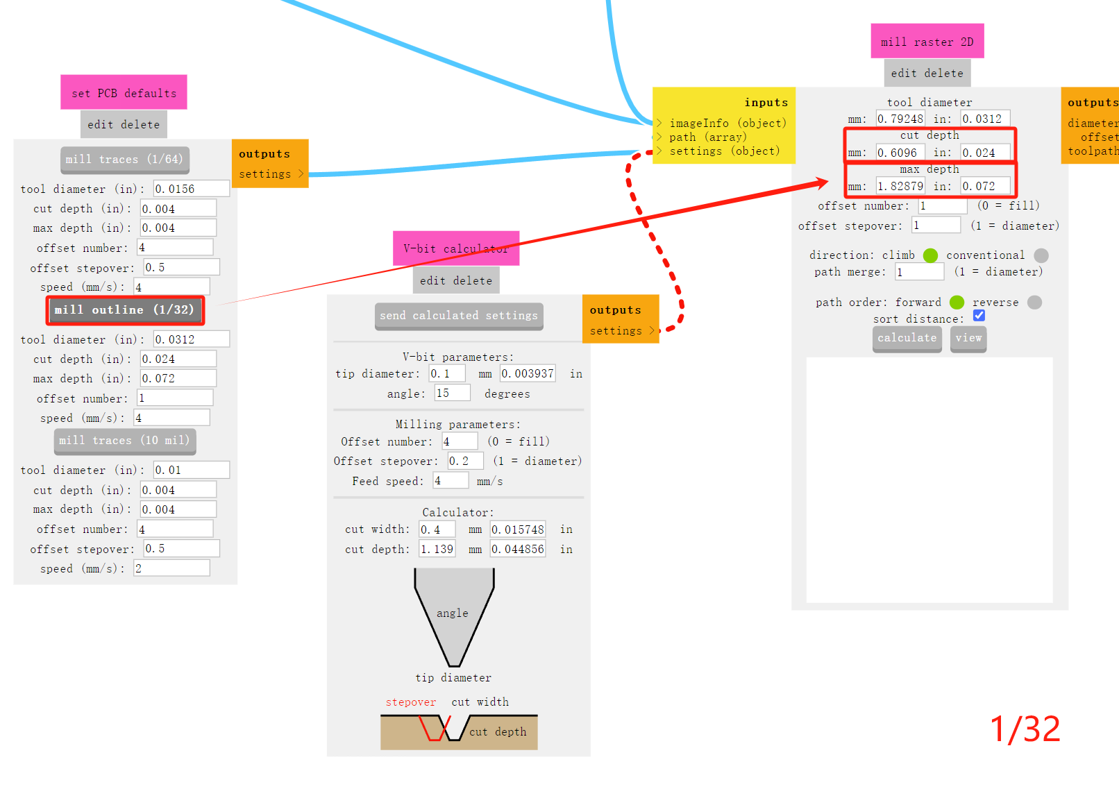
Since there is only an endmill in the lab, I use a common flat-end milling cutter. When milling the internal circuits, the spacing between the circuit circuits and components is relatively small, so I use a 1/64 endmill. When milling the external contours and holes, considering the assembly, the strength and stability of the tool, and the efficiency of drilling, I use a 1/32 endmill.
Select the gray area corresponding to the milling cutter. After clicking, its milling depth will change accordingly. It's a habit. Every time I check whether the cutting parameters and maximum parameters have changed accordingly, in case I don't click and make some low-level mistakes.
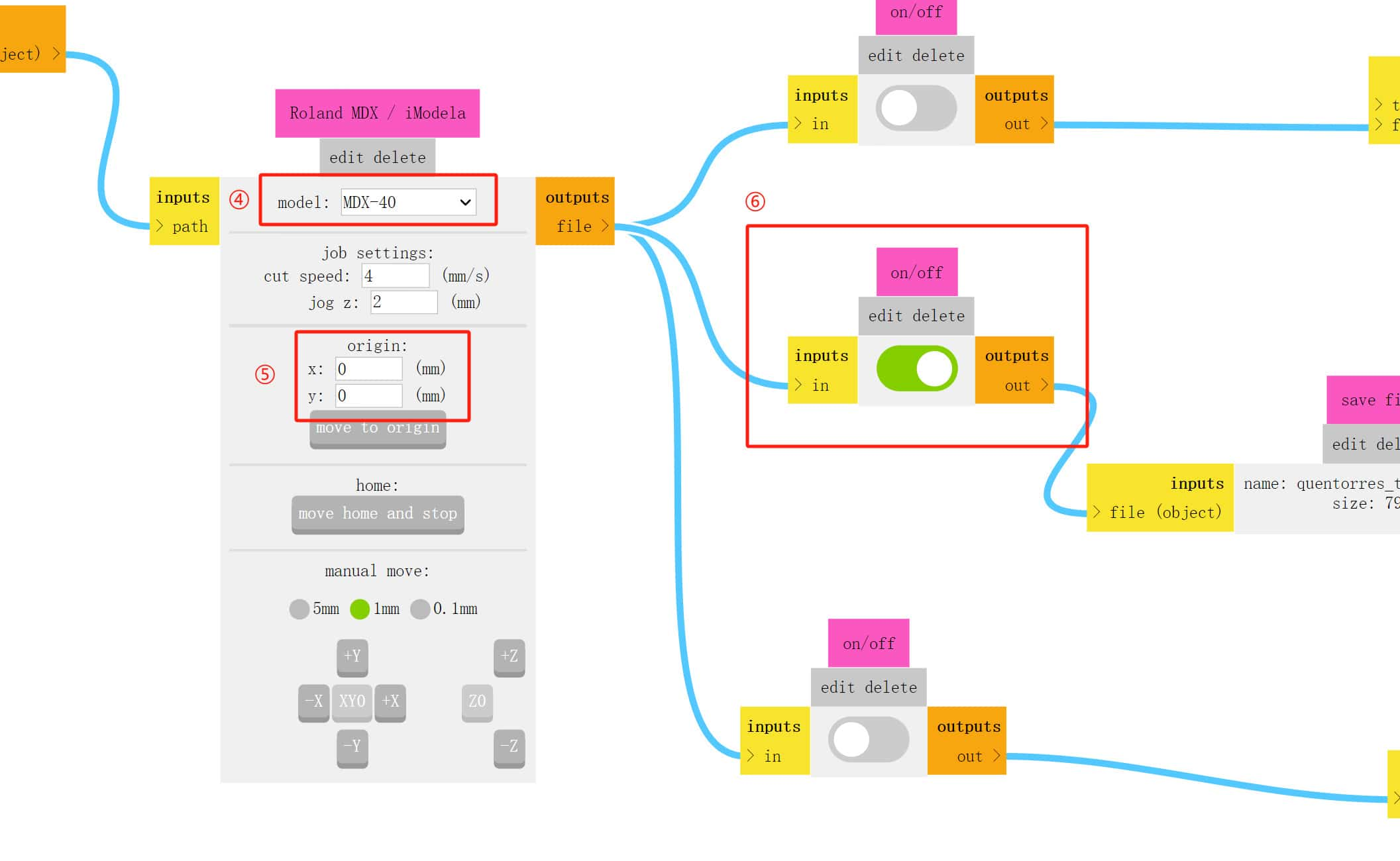
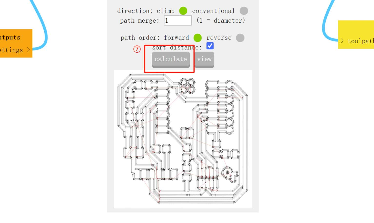
Step3:Select the machine model MDX-40, set xy to 0, so that we can set the origin later, then check the content on the front side and select Save
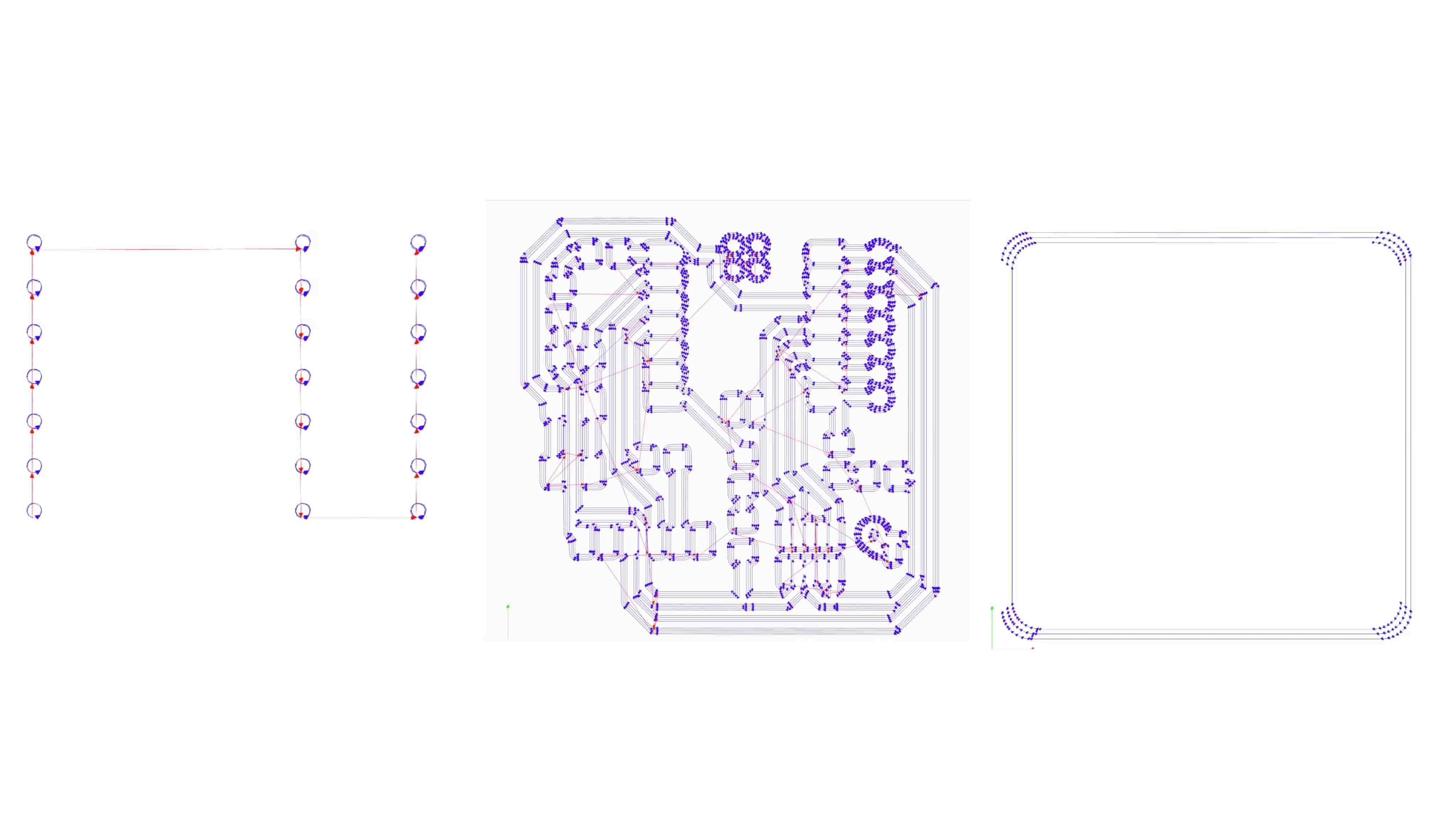
Step4:Click calculate and it will automatically jump to another web page where you can zoom in and out to check whether the path is generated correctly to avoid mistakes when cutting. I will keep this habit.
Our lab has a computer dedicated to Roland, so I downloaded it via a USB drive and imported it into another computer to do the following milling work.
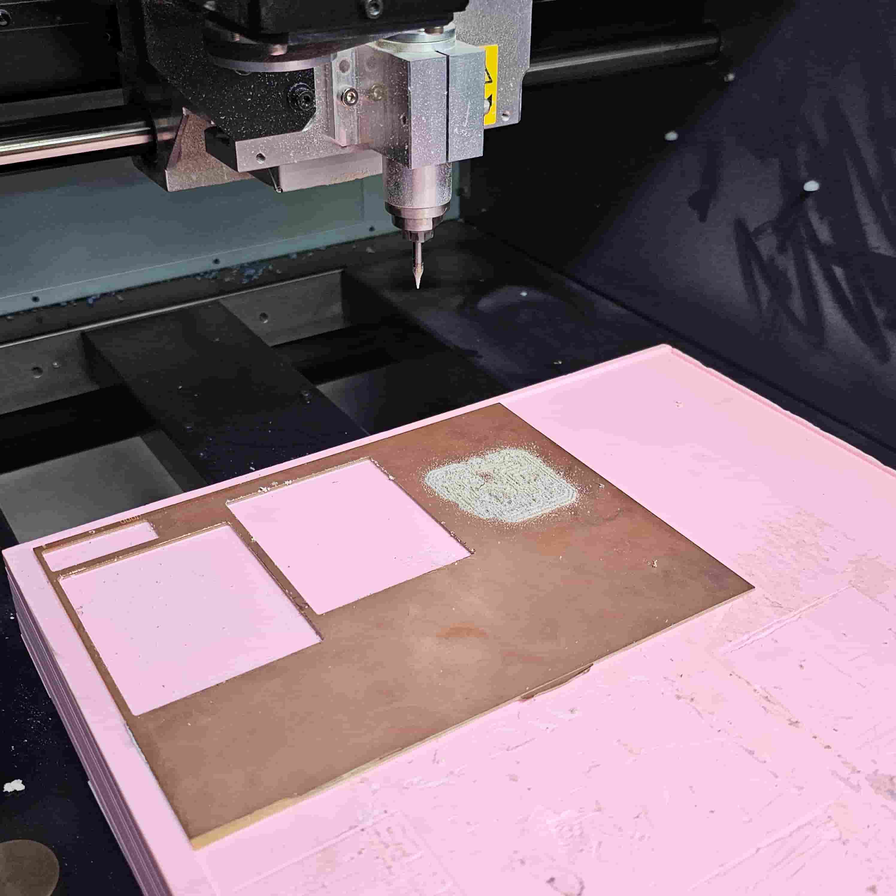
1.2.3 Milling
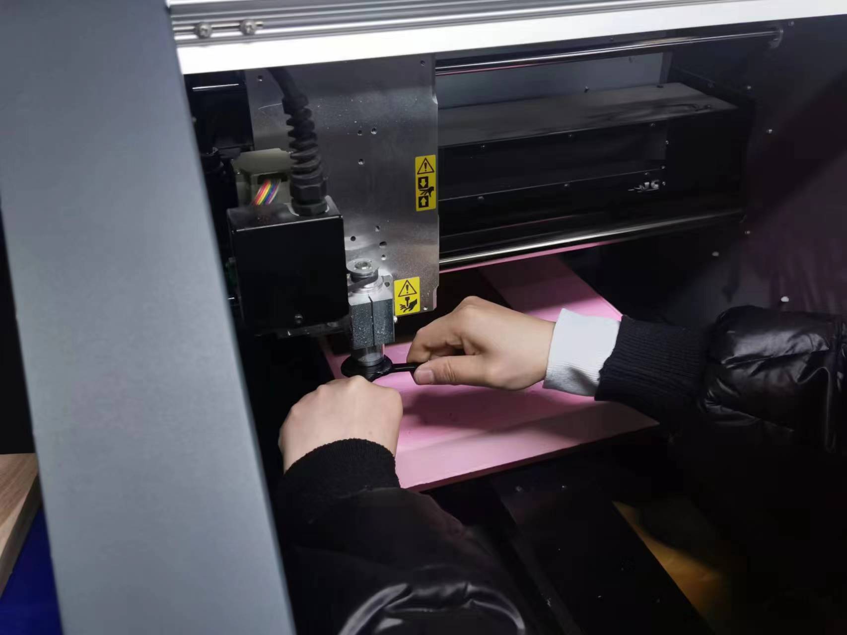
Usually the circuit part is milled first, because it prevents the bottom from moving after the outline is cut off. This means that after the last person uses the circuit board, the knife for milling the outer contour and holes will be left until the end, so my first step is to change the knife.
Use two wrenches here, tighten clockwise and loosen counterclockwise.
Open the Poland Vpanel homepage. The left side of the copper clad board has been milled two-thirds, so I moved to the right side. Since the origin of this machine is in the lower left corner, I used the software to move the cutter head to the lower left corner on the right side flush with the previous design, and clicked "Set XY" to set the origin.
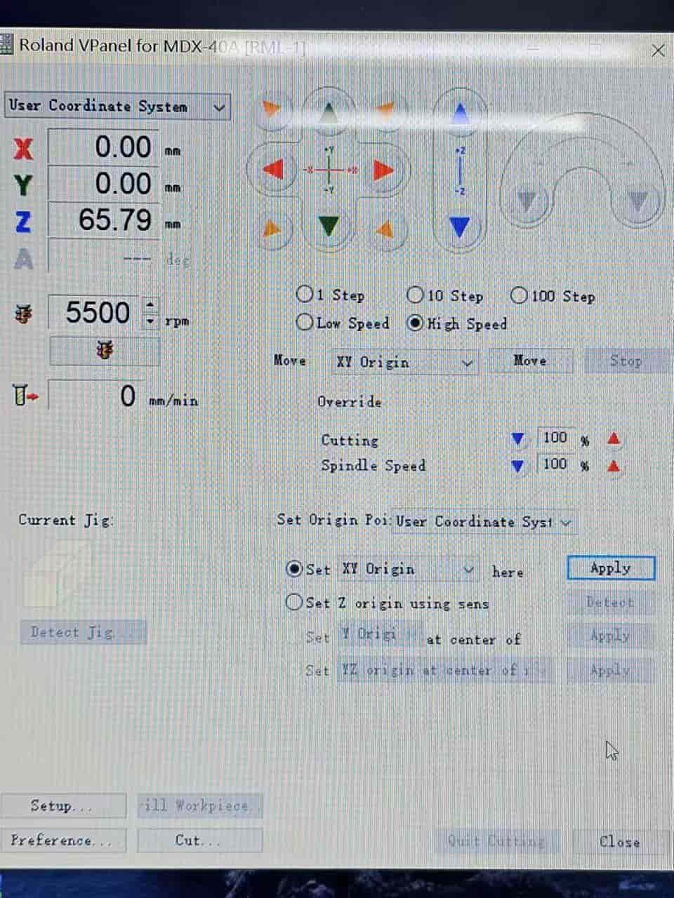
Then use the automatic tool setting instrument, place it under the drill bit, and click "Set Z origin using sens-detect"
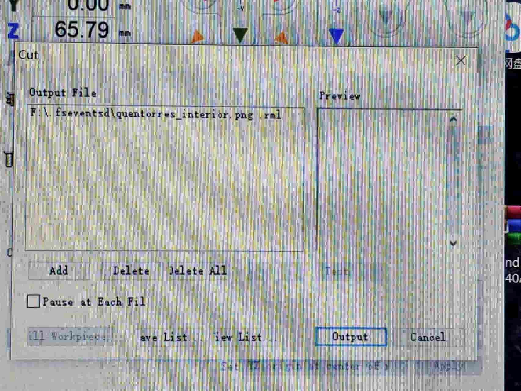
Delete the previous person's file, add the path I generated in mods, and then click export. (Note: If two files are cut together, the one on top will be cut first)
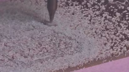
Then start milling, there will be a lot of copper chips, wait for a while...wait...
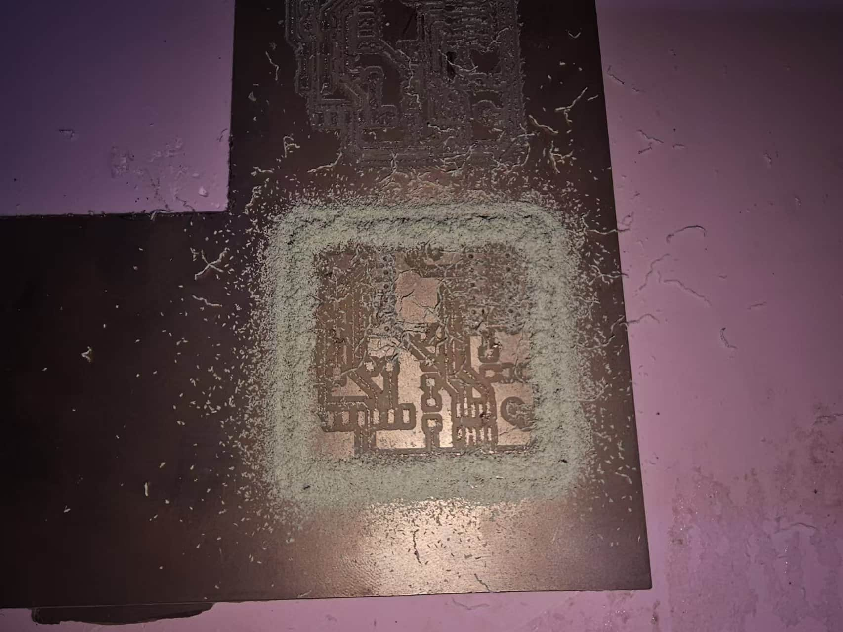
Some problems occurred during the process.
When I first aligned the Z axis, there was a foreign object on the automatic tool setting device, and the Z axis was raised a little. Then I recalibrated the Z axis, based on the first milling, without changing the starting point, and re-milled. The tool seemed to break in the middle. I stopped the machine and removed the tool for inspection. I found that the tool head was a little worn, perhaps because of repeated use? But the front end was long enough, so I re-milled at this position, but perhaps because of repeated milling and some wear on the tool, the small circuit in the middle had been milled off.
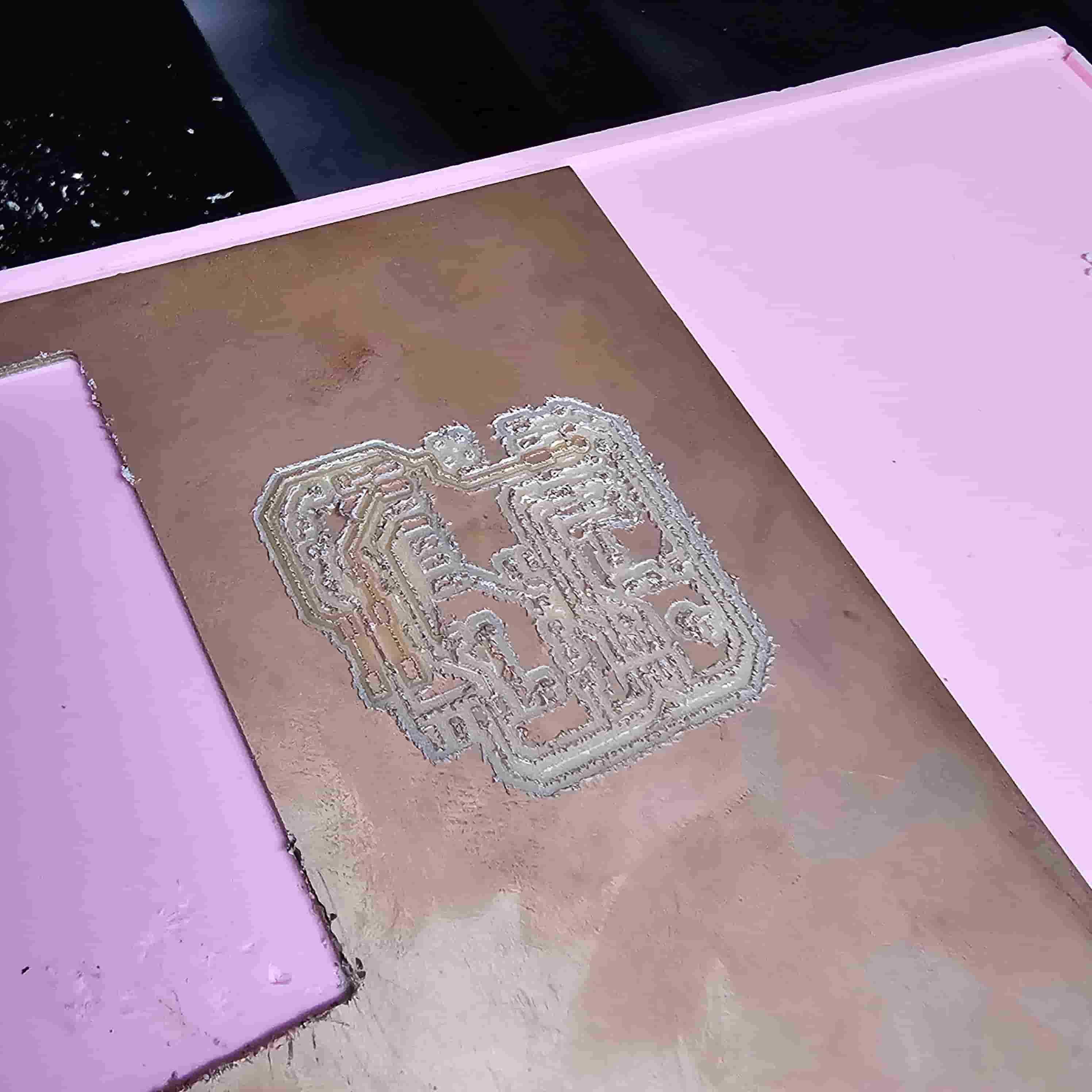
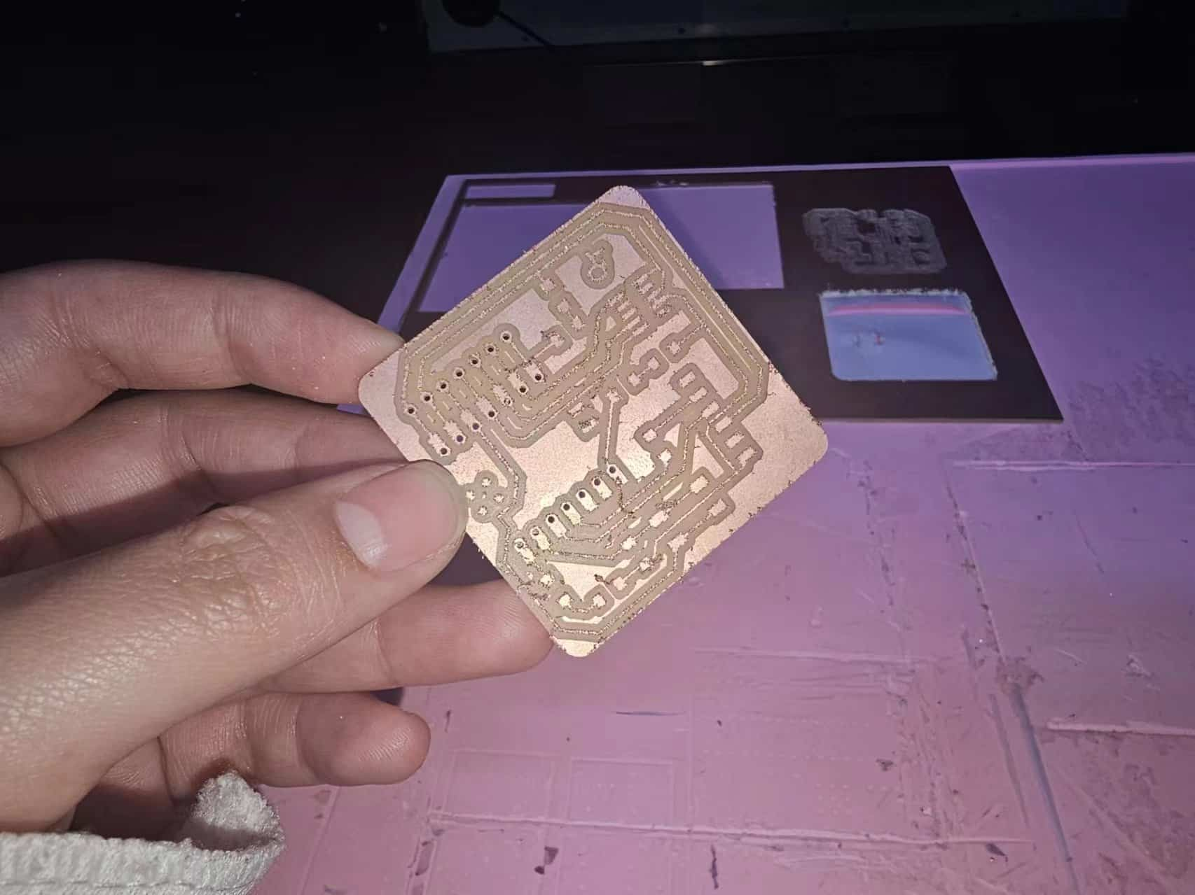
I changed to a new 0.4mm milling cutter, re-set the three axes, started milling, and still waited...waited...
After milling, vacuum it and remove it.
But there are still some rough edges, so I used tweezers to gently clean the edges (I forgot to take a photo here)
1.2.4 Solder
Following the circuit diagram provided by MIT, I embarked on the thrilling journey of soldering.
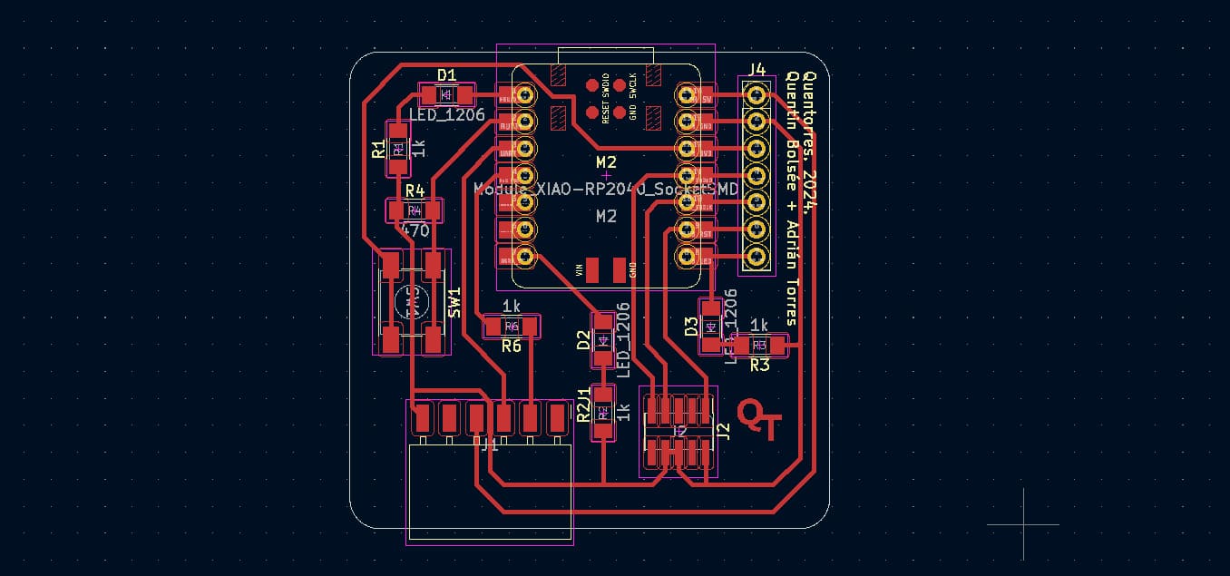
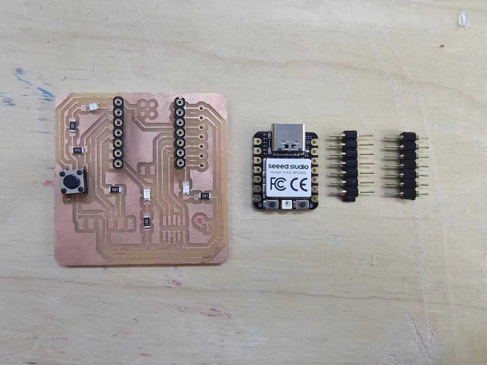
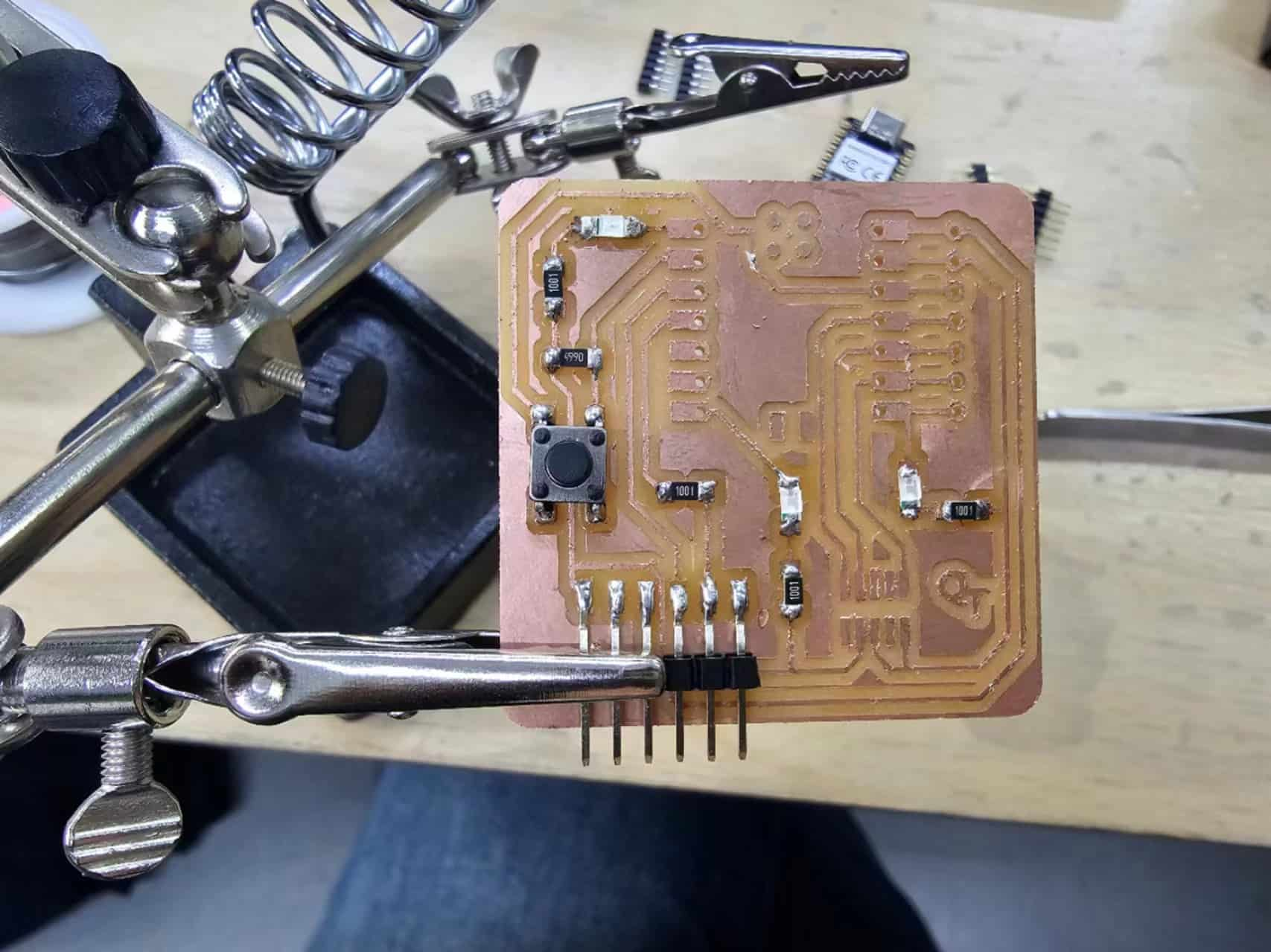
With the help of my colleagues, I found the corresponding components. Since I was not so skilled at it for the first time and was afraid of losing these components, I arranged all the original parts on the circuit board according to the circuit diagram.
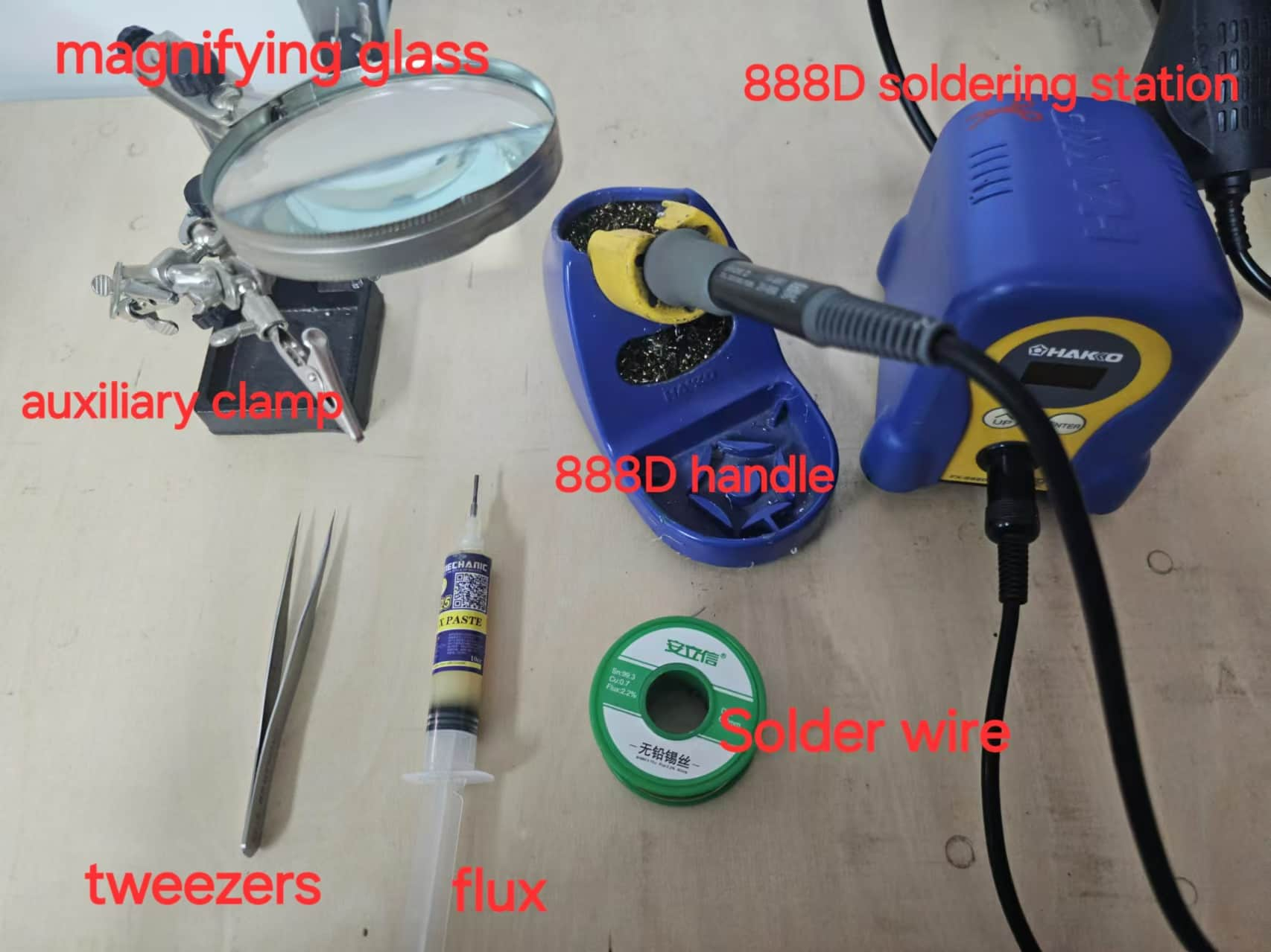
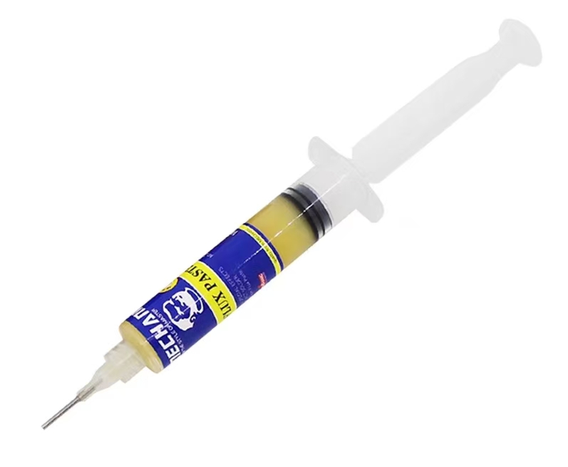
Then take out the soldering station, soldering iron handle, auxiliary clamp, flux paste, tweezers, solder wire
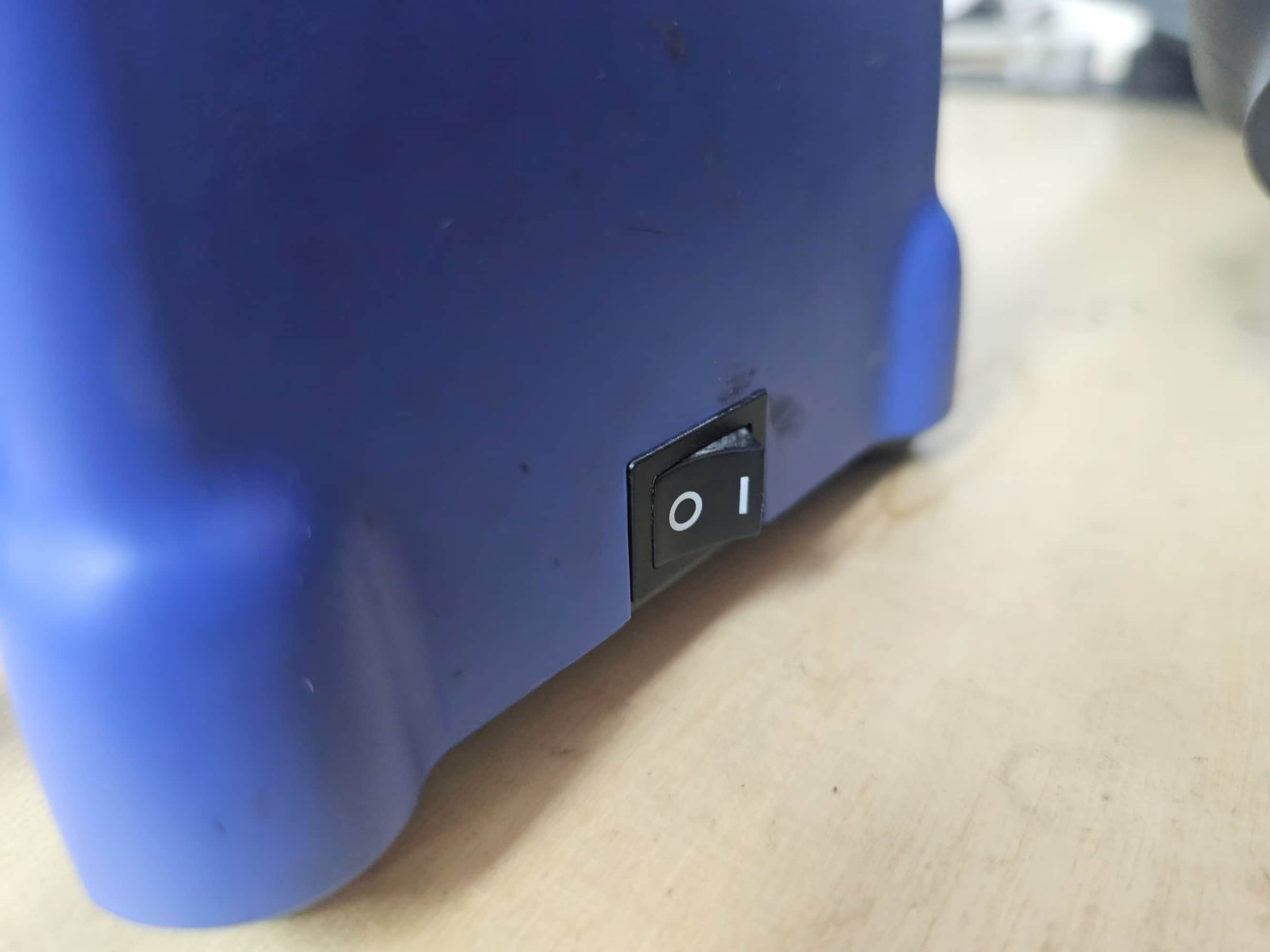
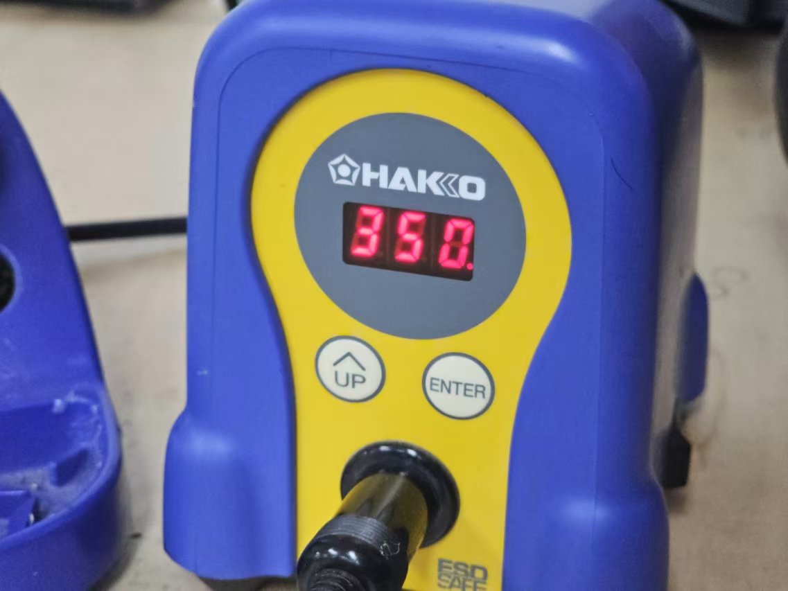
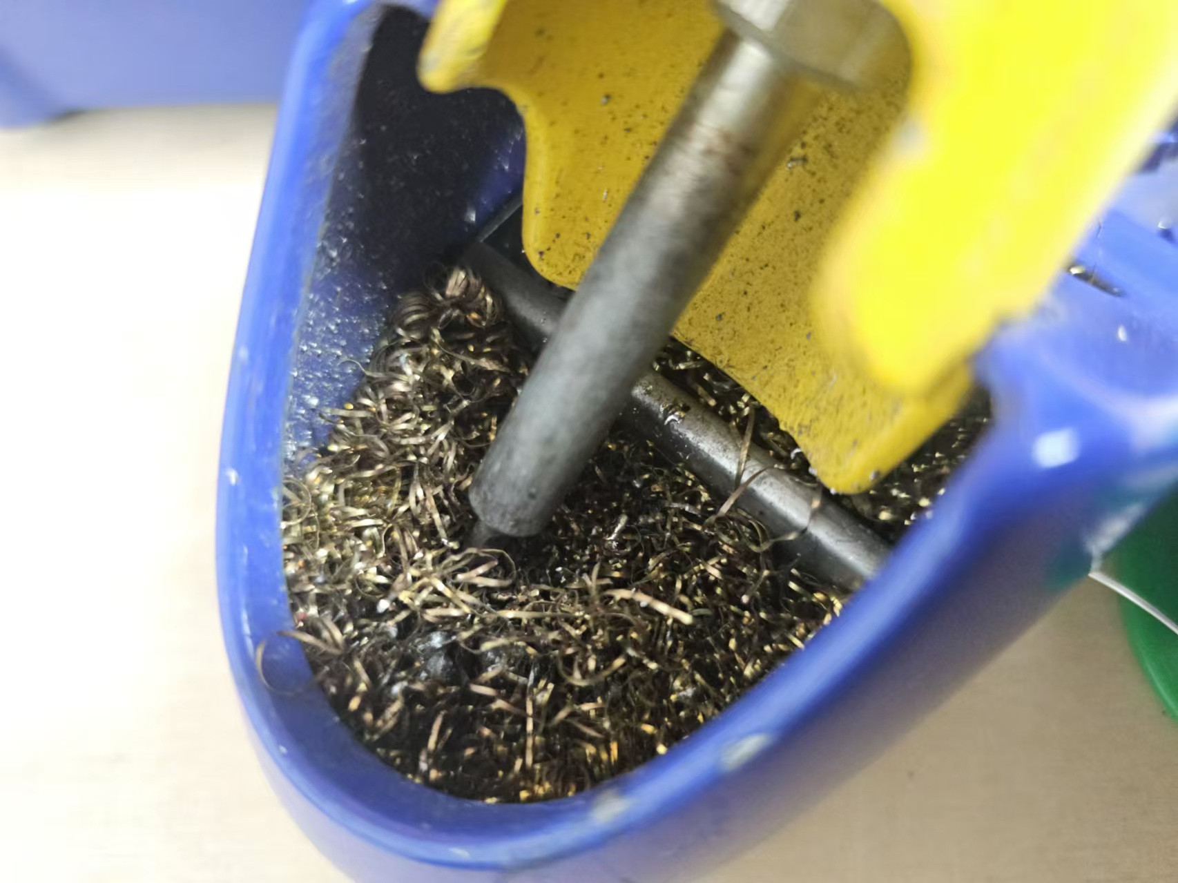
Set the temperature of the soldering iron to 350°, and let the tip of the soldering iron heat up. The steel wool in the soldering iron rack is for cleaning. I usually clean it here before use to facilitate soldering. (Be sure to pay attention to safety, don't get burned, and remember to turn off the power after use).
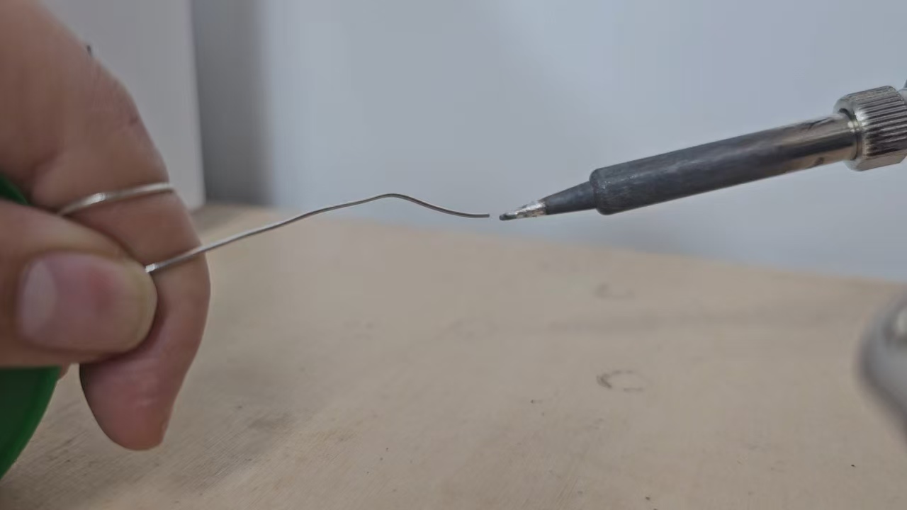
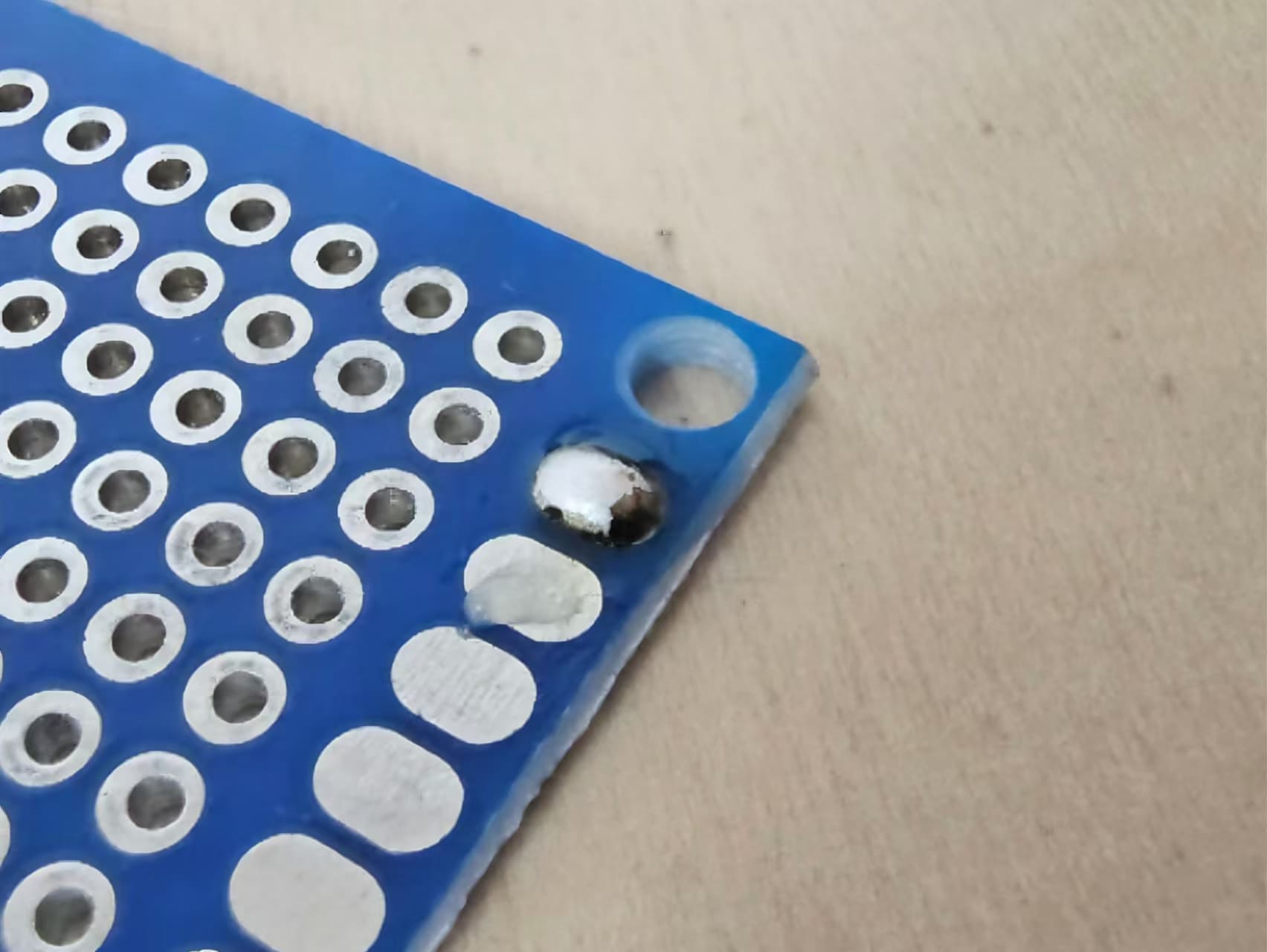
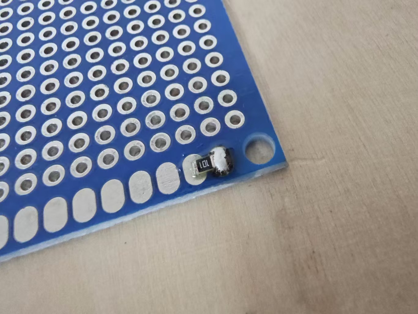
Solder the small components first. Sorry, I forgot to take a photo here, so I will use the practice board to show the process instead. First, I squeezed a little solder paste on the solder joint with a needle. This solder paste is very easy to use. It can effectively remove the oxide on the metal surface and make the tin easier to spread. And this needle is also very easy to use. I can control the amount very accurately and squeeze the solder paste to the right place.
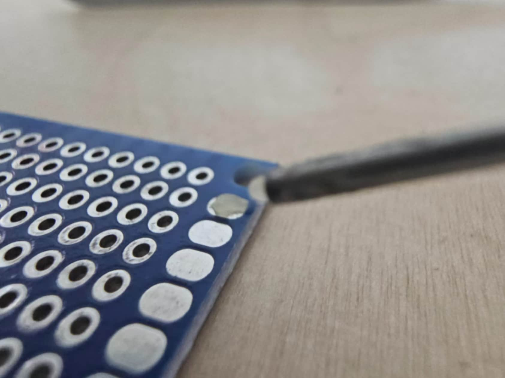
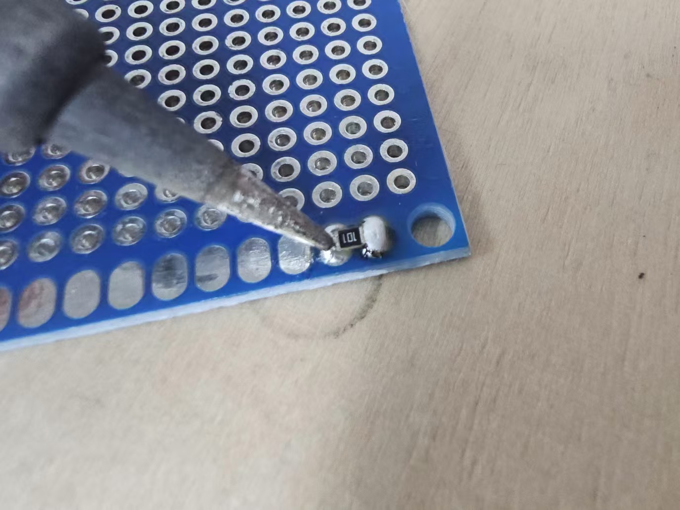
Put a small amount of tin on the tip of the soldering iron, and then dot it on the solder joint that has been coated with solder paste. At this time, the solder can be spread on it very smoothly.
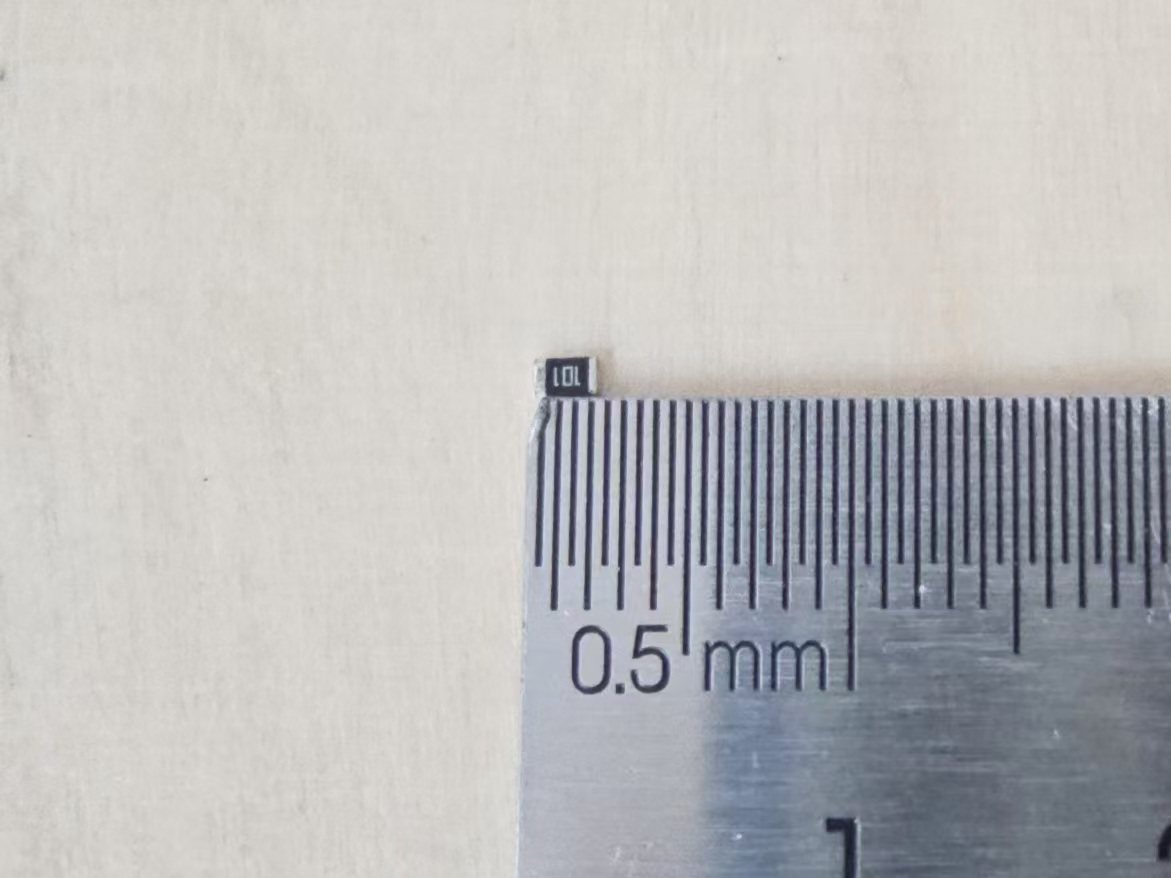
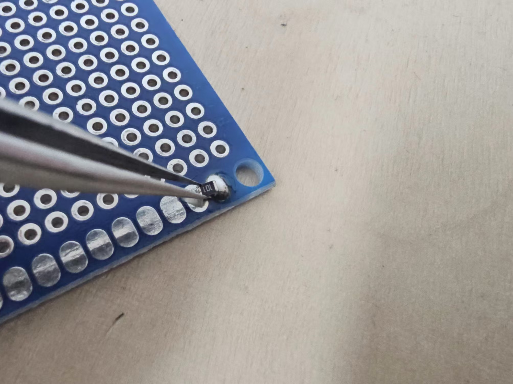
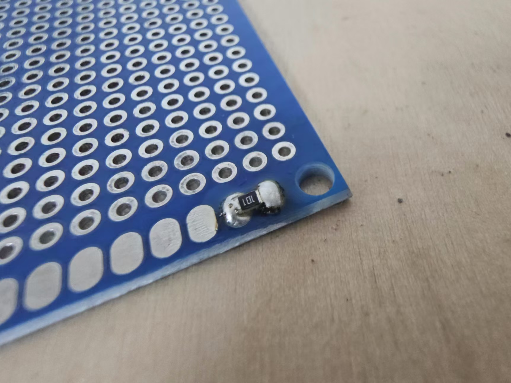
Because the component is very small, you can see its size by comparing it with the ruler. So I need to use tweezers to fix the component, otherwise my hands will be burned. After fixing the component, use the soldering iron tip to heat the part that has just been tinned. You can see that the component is well fixed. Then tin the other side, and the soldering is completed.
Next, solder the pin header and fix it with an auxiliary clip like this, and then fix the single row of female pins.
1.2.5 Test
I will perform two blink tests using the Seeed Xiao RP2040 development board in the Arduino IDE. I followed the official tutorial
A blink:
Two blink: