WEEK 6
Embedded programming
Assignment:
Group Assignment:
- Browse through the data sheet for your microcontroller compare the performance and development workflows for other architectures
Individual Assignment:
- Write a program for a microcontroller development board that you made, to interact (with local input &/or output devices) and communicate (with remote wired or wireless devices)
- Extra credit: use different languages &/or development environments
- extra credit: connect external components to the board
This week, I started to learn more about the microcontroller that I will use for my project. For this, I reviewed the datasheet and also created some programs to get more familiar with the microcontroller's inputs and outputs. To write the programs, I used the Arduino IDE and the Arduino language, as well as the Thonny IDE to program it in Micropython.
Group Assignment
We are going to use the Xiao RP2040 board for my project. It's a board that carries the powerful dual-core RP2040 processor from Raspberry Pi
Specifications:
| Parameter | Description |
|---|---|
| CPU | Dual-core ARM Cortex M0+ processor, flexible clock running up to 133 MHz |
| Storage | 264KB of SRAM, and 2MB of onboard Flash memory |
| I/O PINs | 11 digital pins, 4 analog pins, 11 PWM Pins |
| Interface | 1 I2C interface, 1 UART interface, 1 SPI interface, 1 SWD Bonding pad interface |
| Power supply & Downloading interface | USB Type-C interface |
| LEDs: | 1 user LED, 1 power LED, two LEDs for serial port downloading, 1 RGB LED |
| Button | 1 RESET button, 1 BOOT button |
| Power Pads | For the battery power supply |
| Software compatibility | Support Micropython / Arduino / CircuitPython |
| Cover | Projection cover for protecting the circuit |
| Dimensions | 21x17.5 mm |
These are the pins available on the board, along with the functions or characteristics of each one:
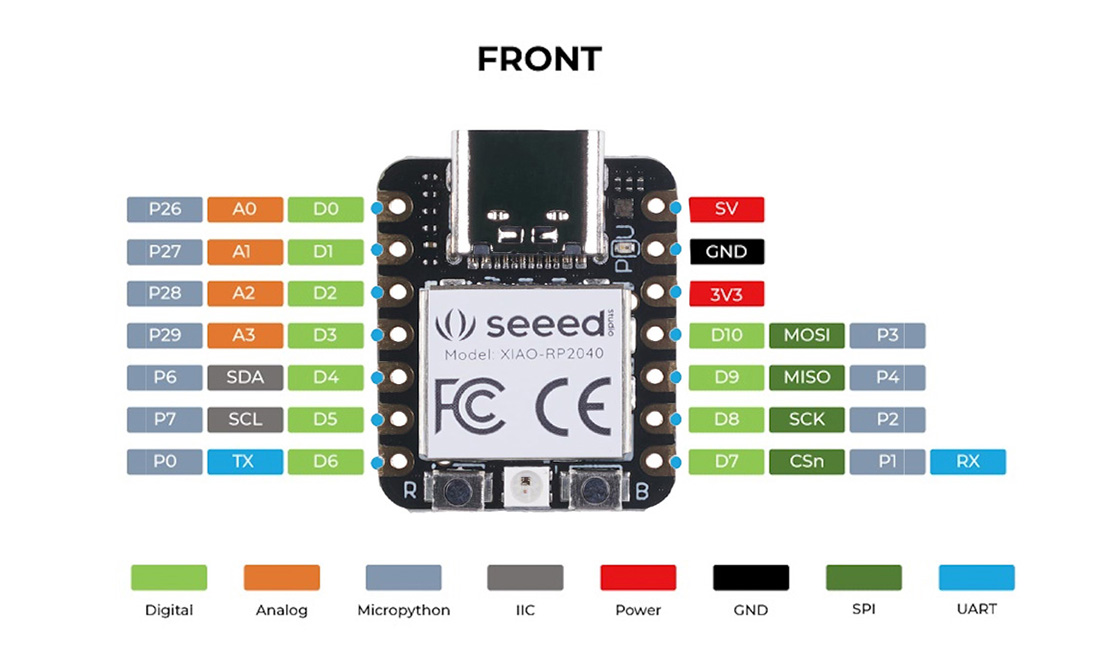
An important point to mention here is that the working voltage is 3.3V, although it has a 5V output that can be used to power an external device that uses that voltage. It's important to remember not to connect more than 3.3V to the pins, as it could damage the microcontroller.
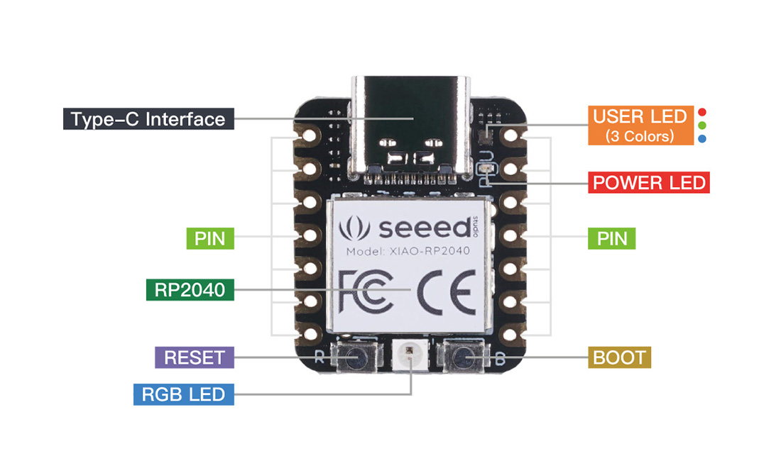
These are some of the hardware features of this board.:
We also tedted the Arduino Uno by controling servo.
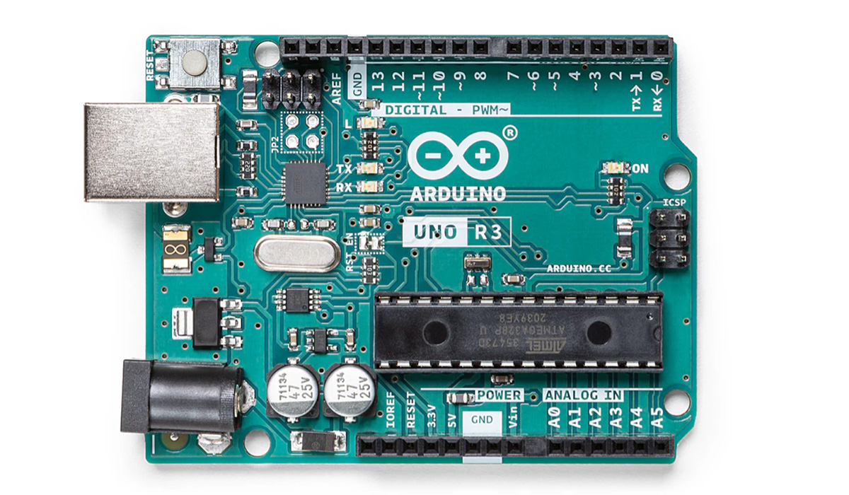
Specifications:
| Parameter | Description |
|---|---|
| CPU | AVR 8 bit processor, clock running up to 16 MHz |
| Storage | 2KB of SRAM, and 32KB of Flash memory |
| I/O PINs | 14 digital pins, 6 analog pins, 6 PWM Pins |
| Interface | 1 I2C interface, 1 UART interface, 1 SPI interface |
| Power supply & Downloading interface | USB Type-B interface |
| LEDs: | 1 user LED, 1 power LED, two LEDs for serial port downloading |
| Button | 1 RESET button |
| Software compatibility | Arduino |
This is the code:
//ARDUINO CODE TO CONTROL A SERVO
#include <Servo.h>
Servo myServo;
void setup() {
// Servo pin 9
myServo.attach(9);
}
void loop() {
// Move servo to 0 degrees
myServo.write(0);
delay(1000); // 1 second delay
// Move servo to 90 degrees
myServo.write(90);
delay(1000); // 1 second delay
// Move servo to 180 degrees
myServo.write(180);
delay(1000); // 1 second delay
// Move servo to 90 degrees
myServo.write(90);
delay(1000); // 1 second delay
}
We also tested Arduino MKR WIFI 1010 board by running the same program to control the servo
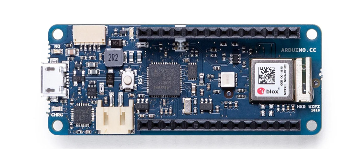
Specifications:
| Parameter | Description |
|---|---|
| CPU | SAMD21 Cortex M0+ 32 bit ARM processor, clock running up to 48 MHz |
| Storage | 32KB of SRAM, and 256KB Flash memory |
| I/O PINs | 8 digital pins, 7 analog pins, 13 PWM Pins |
| Interface | 1 I2C interface, 1 UART interface, 1 SPI interface, WIFI |
| Power supply & Downloading interface | USB Micro interface |
| LEDs: | 6 BIULTIN |
| Button | 1 RESET button |
| Software compatibility | Arduino |
| Dimensions | 61.6x25 mm |
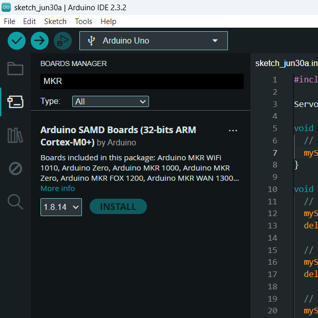
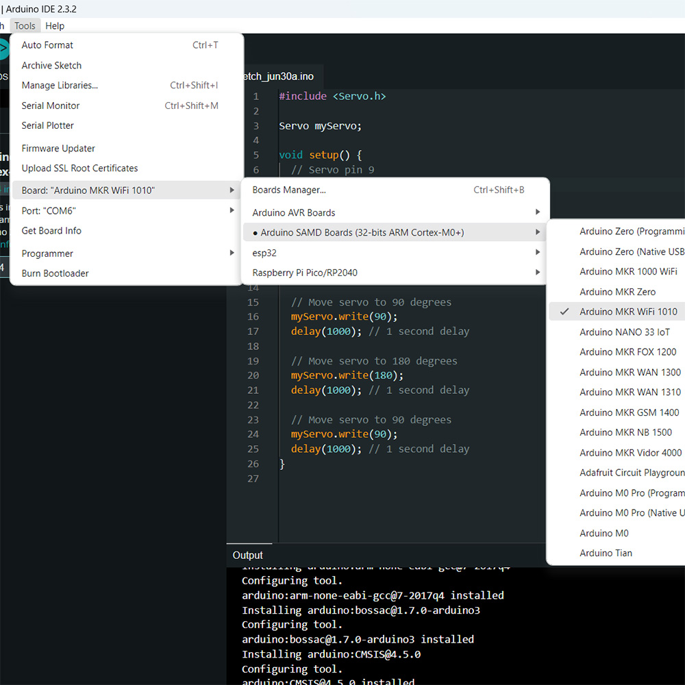
This board is not installed by default in the Arduino IDE, so you need to go to the Board Manager and install it. Then, select it from Tools > Board > Arduino SAMD Boards.
This is the code:
//ARDUINO MKR WIFI 1010 CODE TO CONTROL A SERVO
#include <Servo.h>
Servo myServo;
void setup() {
// Servo pin 3
myServo.attach(3);
}
void loop() {
// Move servo to 0 degrees
myServo.write(0);
delay(1000); // 1 second delay
// Move servo to 90 degrees
myServo.write(90);
delay(1000); // 1 second delay
// Move servo to 180 degrees
myServo.write(180);
delay(1000); // 1 second delay
// Move servo to 90 degrees
myServo.write(90);
delay(1000); // 1 second delay
}
Individual Assignment
Arduino: For the following programs, I used the Arduino IDE, which I found to be quite easy and practical to use. To configure it for use with the Xiao RP-2040 which is integrated into the Quentorres board we made in the Electronic Production week, I used the following link from Earlephilhower as a reference.
The first thing I did was create a program to blink a LED. I also did this during the electronics production week. In this case, it helped me to test that the board's LEDs were working correctly. It's a very simple program that turns the LED connected to the pin 26 of the Xiao-RP2040 on and off every 200 ms.
void setup() {
pinMode (26, OUTPUT);
}
void loop() {
digitalWrite(26, HIGH);
delay(200);
digitalWrite(26, LOW);
delay(200);
}
The next program turns on the LEDs connected to pins 26, 0, and 1 each time the button connected to pin 27 is pressed.
void setup() {
pinMode (26, OUTPUT);
pinMode (0, OUTPUT);
pinMode (1, OUTPUT);
pinMode (27, INPUT);
}
void loop() {
int state=digitalRead(27);
if (state==HIGH){
digitalWrite(26,HIGH);
digitalWrite(0,HIGH);
digitalWrite(1,HIGH);
}
else {
digitalWrite(26,LOW);
digitalWrite(0,LOW);
digitalWrite(1,LOW);
}
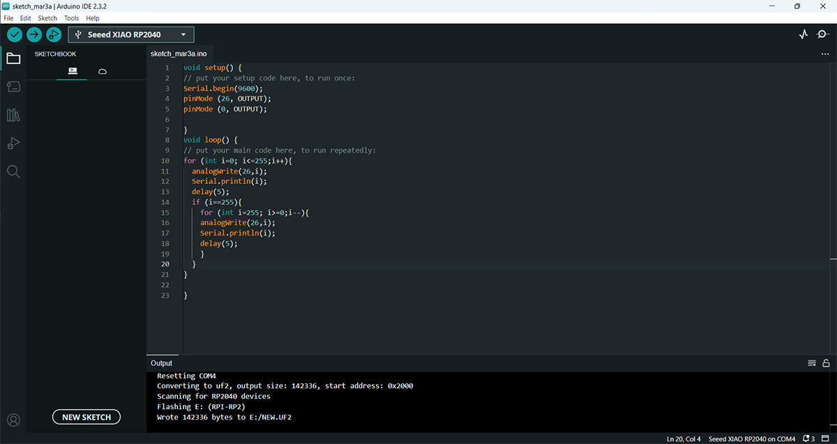
}The next program seems a bit more interesting to me; it's a program that varies the brightness of the LED. For this, I used pin 26, which also supports analog output. To test the variation, I also enabled serial communication on pin 0.
void setup() {
Serial.begin(9600);
pinMode (26, OUTPUT);
pinMode (0, OUTPUT);
}
void loop() {
for (int i=0; i<=255;i++){
analogWrite(26,i);
Serial.println(i);
delay(3);
if (i==255){
for (int i=255; i>=0;i--){
analogWrite(26,i);
Serial.println(i);
delay(3);
}
}
}
}
The following program uses a Rotary angle sensor (it has 10k ohms resistance potentiometer and 300 degrees angular range) to adjust the brightness of an LED. For this purpose, the potentiometer and the LED are connected to analog inputs. To check the status of the input, I also display the value on the Arduino Serial Monitor through serial communication.
void setup() {
    Serial.begin(9600);
    pinMode(28, INPUT);
    pinMode(26,OUTPUT);
}
void loop()
{
    int sensor_value = analogRead(28);
    Serial.println(sensor_value);
    int led_value;
    led_value=map(sensor_value, 0, 1023, 0, 255);
    analogWrite(26,led_value);
    delay(50);
}
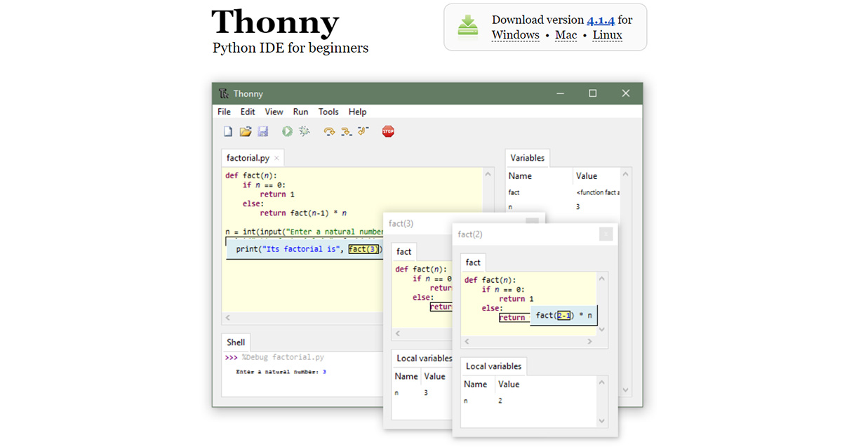
MicroPython: The board I'm using also supports MicroPython, so to test it, I downloaded Thonny, which is an IDE designed for beginners who want to use Python. The interface is quite simple to use.
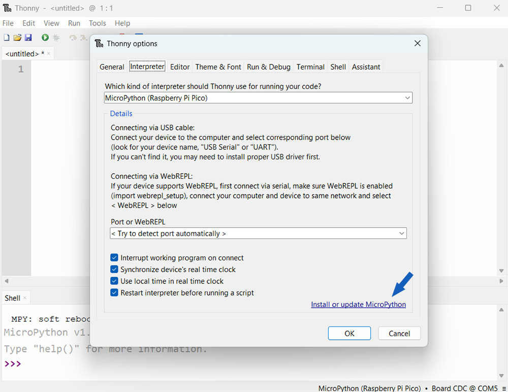
It's also necessary to configure it to use it with the Xiao RP-2040. For this, you need to go to: Tools > Options > Interpreter and there select MicroPython (Raspberry Pi Pico) and choose "Try to detect port automatically" each time the microcontroller is connected.
To connect the Xiao RP2040 board to Thonny, it's necessary to connect it to the PC while holding down the BOOT button. When the PC recognizes the board, the message 'RPI-RP2' will be displayed as a notification on the desktop.
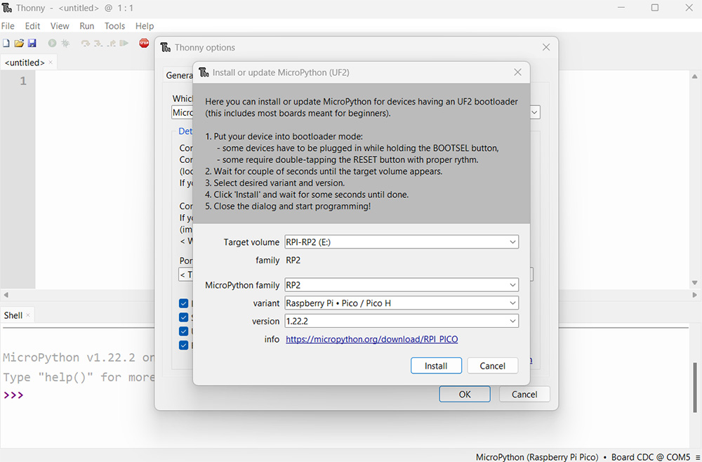
After that, it's necessary to install or update MicroPython
After clicking on 'Install or update MicroPython', a window will open where you can select the variant and version of MicroPython
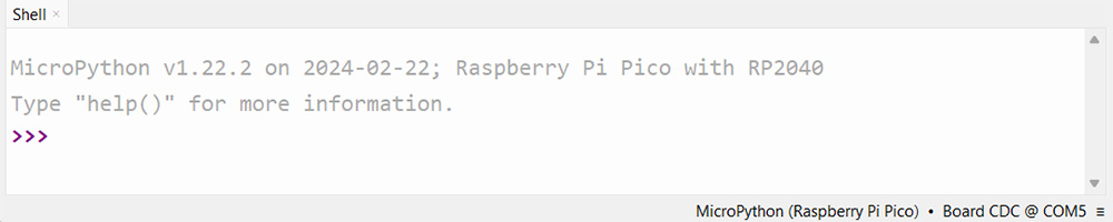
Once the installation is complete, the following message will be displayed.
To test that it has been configured correctly, use the following program in MicroPython to turn the LED on pin 26 on and off every second.
from machine import Pin, Timer
led = Pin(26, Pin.OUT)
Counter = 0
Fun_Num = 0

def fun(tim):
    global Counter
    Counter = Counter + 1
    print(Counter)
    led.value(Counter%2)

tim = Timer(-1)
tim.init(period=50, mode=Timer.PERIODIC, callback=fun)