WEEK 5
3D scanning and printing
Assignment:
Group Assignment:
- Test the design rules for your 3D printer(s)
Individual Assignment:
- Design and 3D print an object (small, few cm3, limited by printer time) that could not be made subtractively
- 3D scan an object (and optionally print it)
This week, I had the chance to try out the 3D printers at the lab. The lab has several printers that use different technologies, such as Fused Deposition Modeling (FDM) and Stereolithography (SLA). I focused on the FDM printers this week. I also tried a 3D scanner.
Group Assignment: Test the design rules for your 3D printer(s)
The first thing I did was to test the printer's performance with the tests we covered in class. Of course, the result of the prints also depends on the parameters chosen, such as the extruder temperature, speed, etc. What I noticed is that some printers already have these parameters defined/recommended depending on the type of material, so I used the recommended values.
I conducted some tests that we saw in clases. I used a Creator Pro printer:
These are the main features of the printer:
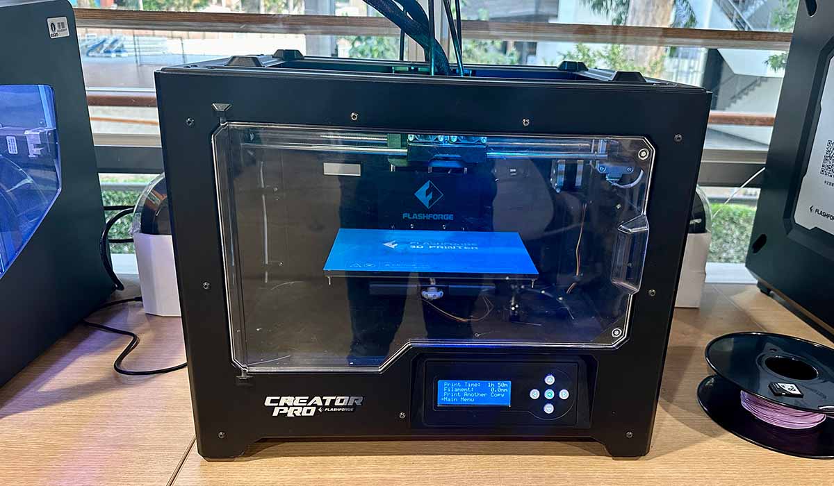
- Build Volume: 227 x 148 x 150 mm
- Layer Resolution High: 0.10 mm
- Print Speed Max: 100 mm/s
- Nozzle Diameter: 0.4 mm
- Filament Diameter: 1.75 mm
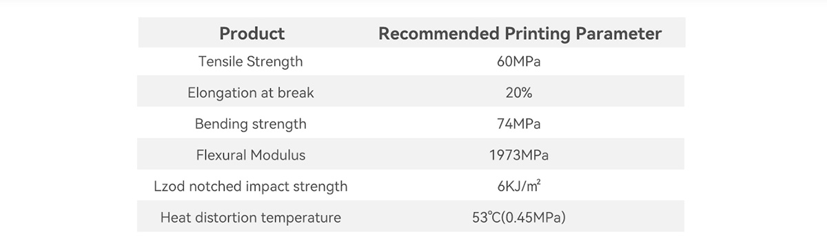
For the tests, I used PLA+ from the Esun brand. PLA is one of the most popular materials for printing. It is biodegradable under certain conditions since it is made from corn. It has a low printing temperature (190-220 degrees Celsius). In the following table, we can see some mechanical characteristics of PLA+ according to the manufacturer:
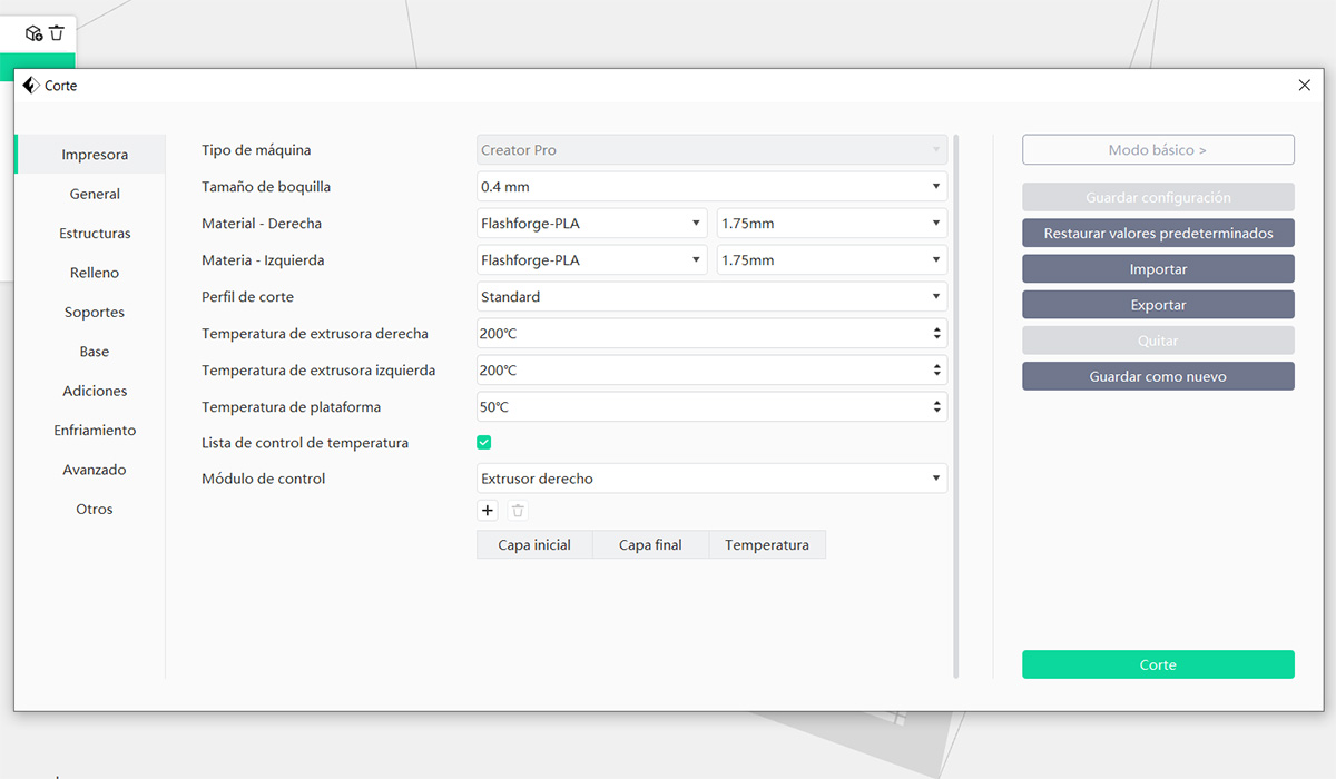
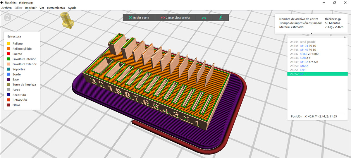
To slice, I used the FlashPrint with the standard configuration, 3 wall lines, 3 top and bottom layers, and 15% infill.
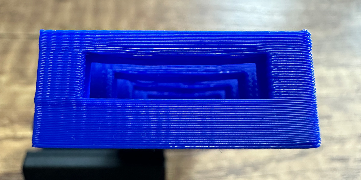
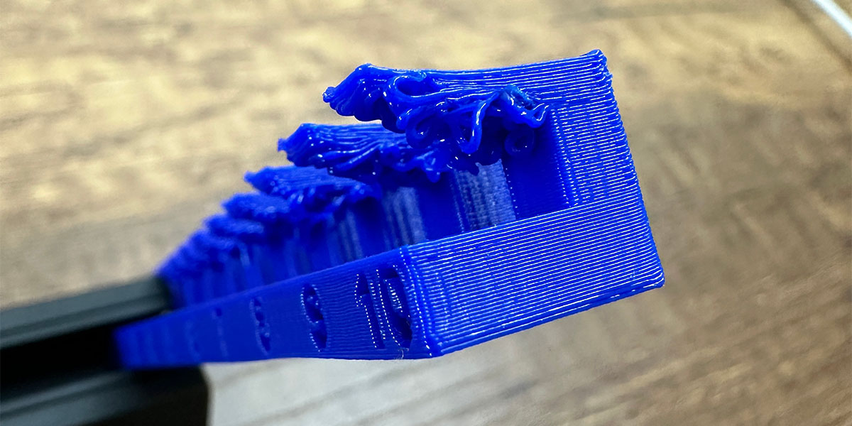
The bridge test surprised me because it yielded good results even for bridges measuring 20 mm in distance. However, a slight deformation can be seen from the sixth bridge, which measures 12 mm.
In the following image, you can see how it deforms with a bridge that is 20 mm wide.
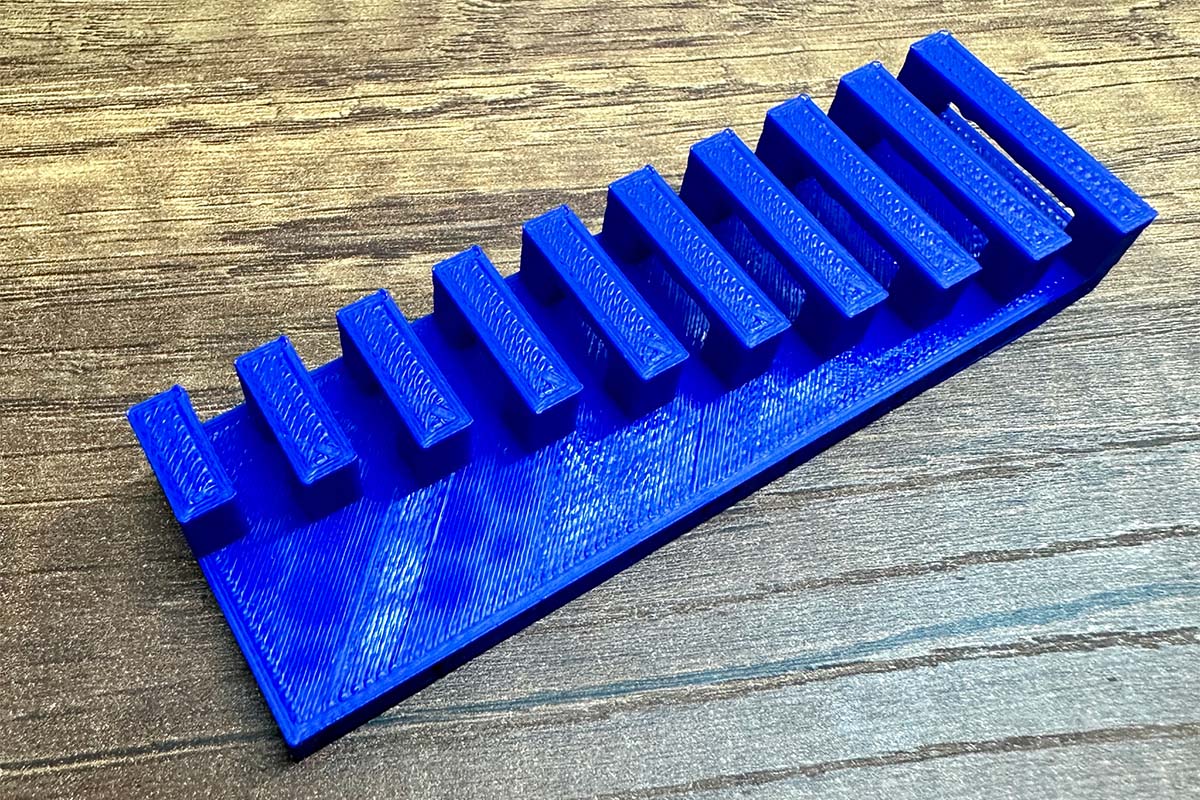
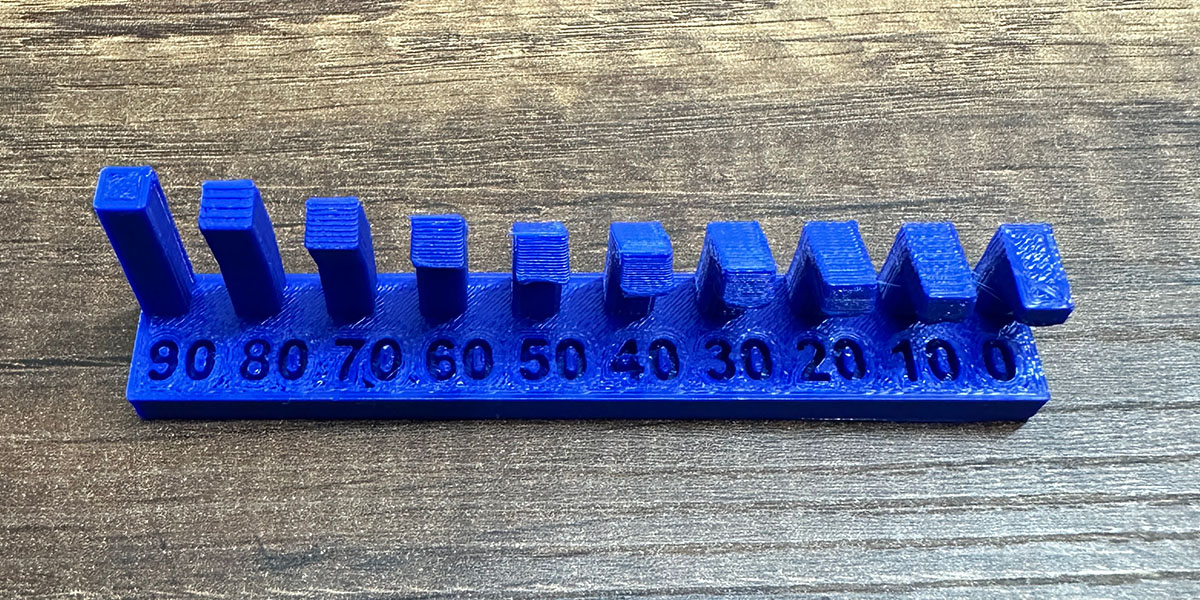
The angle test is used to see how much inclination the walls of the model can have before they start to deform, and also to know at which points it will be necessary to use supports. In the following image, you can see that the printer delivers good quality up to the fifth or sixth tower, which are at 50-40 degrees from the horizontal. Beyond that, the structure deforms significantly, and it would be necessary to use supports.
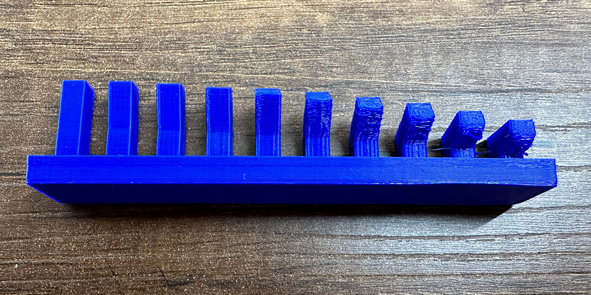
As expected in the overhang test, the piece starts to deform significantly from the third tower, and poor quality is visible right from the first tower.
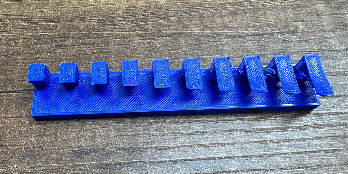
This is the deformation that occurs with a 10 mm wide overhang. As you can see, there is quite a noticeable deformation. In these cases, it is advisable to use supports or add a 45-degree angle when there is a change in section.
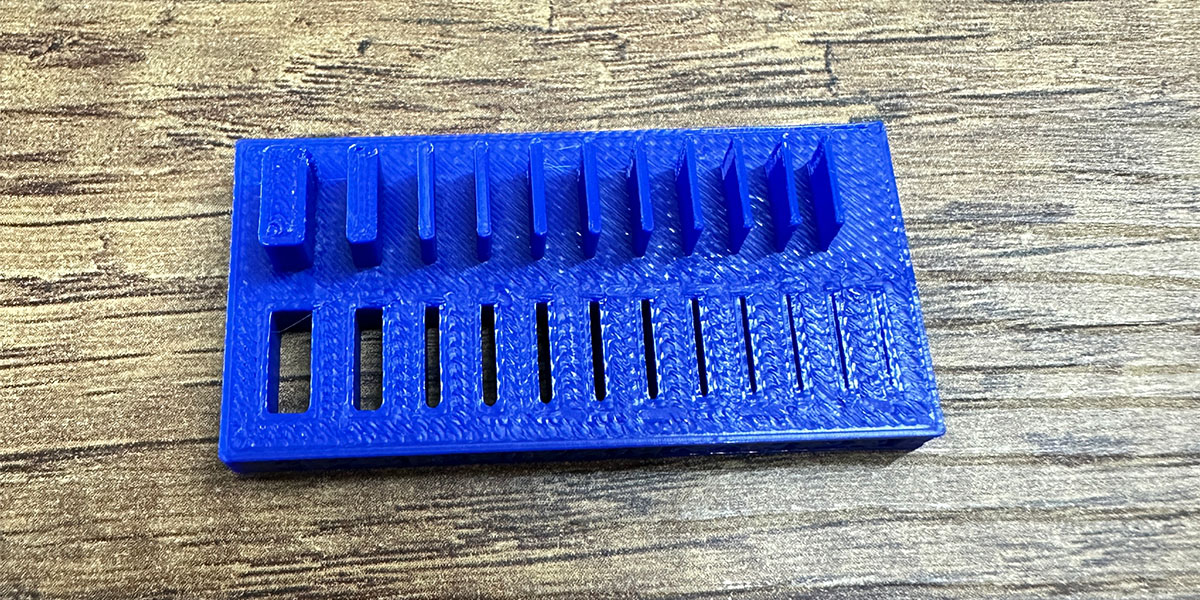
The clearance test is used to determine the tolerance that should be used in joints if designing models with multiple movable parts. As seen in the following image, free movement can be achieved with up to 0.4 mm of clearance. With 0.3 mm, movement is also possible, but the fit is tighter. With clearances less than 0.2 mm, the parts are stuck together.
The thickness test is used to determine how thin the walls of our designed models can be. It's important to pay attention to small thicknesses, as the walls may not have a good finish, or the slicer we use might not recognize them.
Individual Assignment: Design and 3D print an object that could not be made subtractively
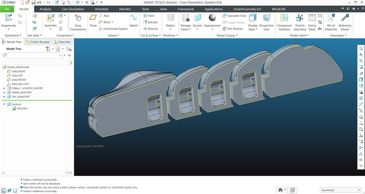
To apply all the learning I gained from conducting tests on the printer, I created an articulated model of a small snake, though the head ended up looking more like that of a crocodile, haha. I used Creo for the design. Below, I highlight some of the most important parts.
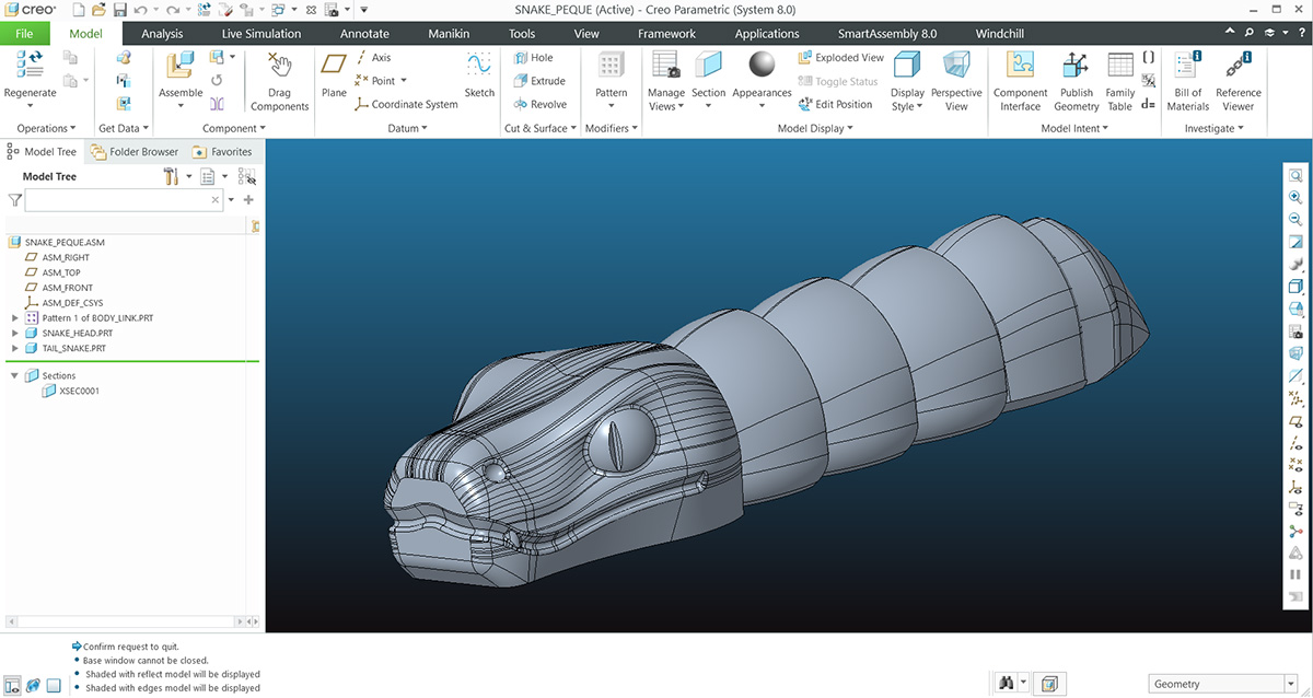
The following image shows a section of the model. Here, you can see the shape of the joints, which were designed with a 45-degree angle to avoid the use of supports. Also, to ensure free movement, there is a 0.5 mm difference between the diameters of the axle and the hole of the joints. Additionally, there is a large surface that is attached to the bed to prevent the piece from detaching.
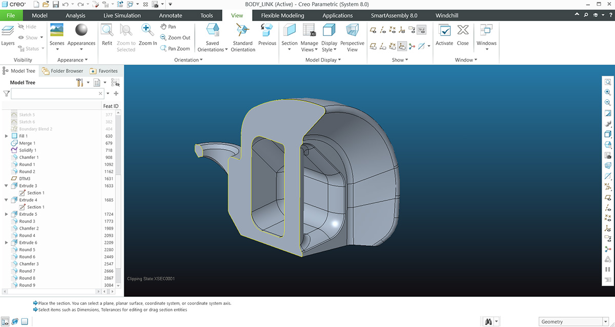
Here, you can see in more detail how the links of the snake's body were designed. I tried to ensure that the angles were greater than 40 degrees to avoid the use of supports.
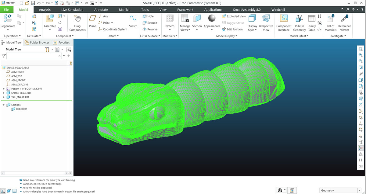
After finishing the design, I exported it in STL format to take it to the printer's slicer.
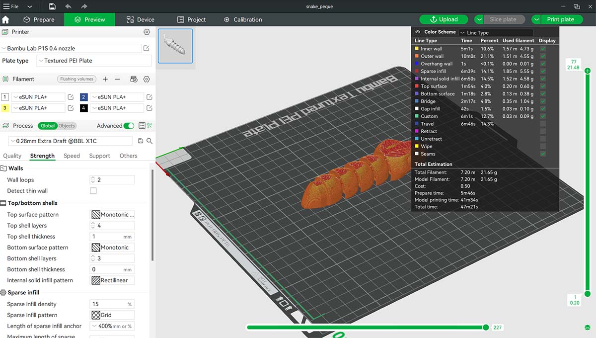
I used Bambu Studio to slice it, and printed it on a Bambu P1S printer with a layer height of 0.28 mm, using the parameters recommended by the program. It takes 47 minutes.
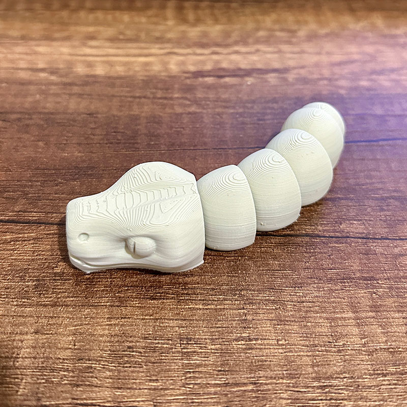
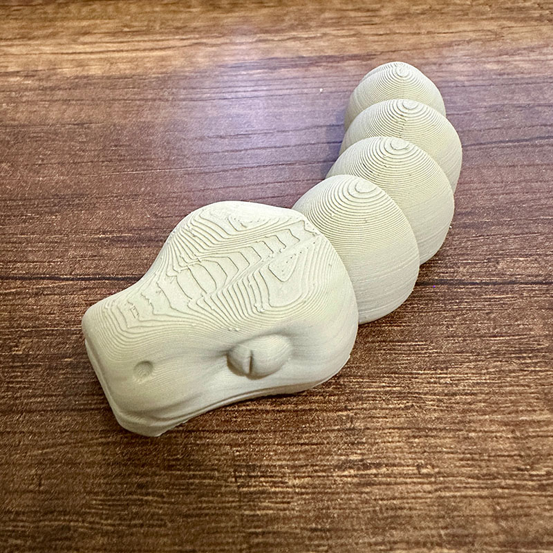
This is the result of the snake, printed in PLA. As you can see on the head, the layer steps are quite noticeable due to the nearly horizontal surfaces. This could be improved by reducing the layer height, but it would also increase the printing time.
Individual Assignment: 3D scan an object
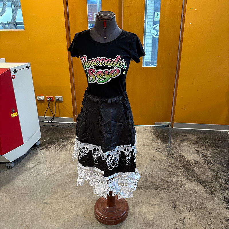
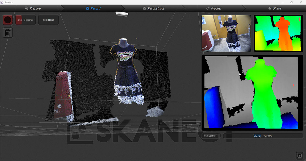
The 3D scanning part also seemed interesting to me. In the lab, we have 2 3D scanners: an Xbox Kinect and a 3D Systems SENSE. This time, I tried the 3D Systems SENSE by scanning a mannequin.
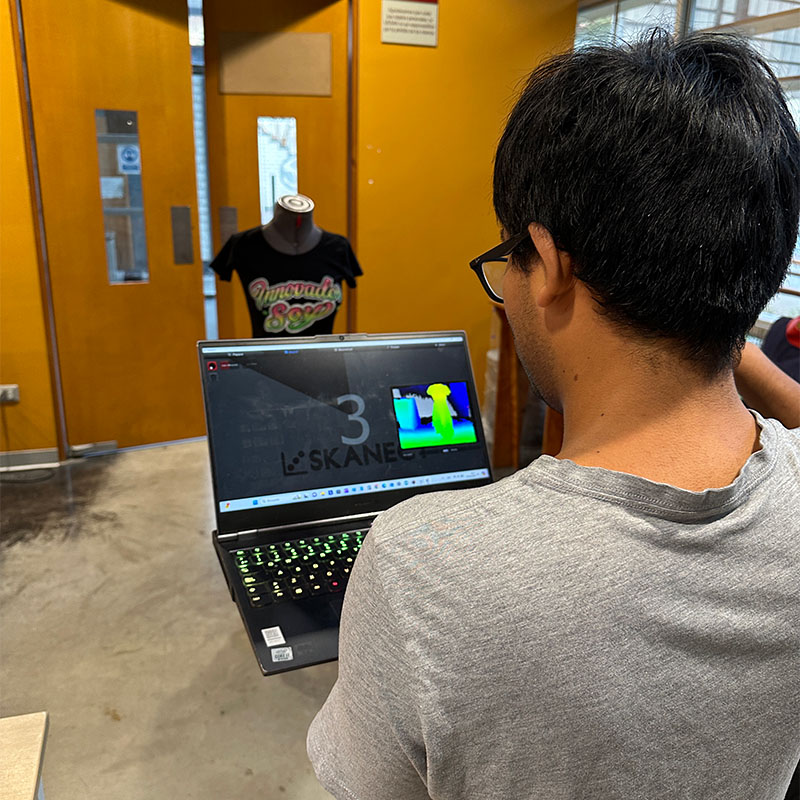
To perform the scan, I also used Skanect software, which is a very user-friendly application. It is paid software
Skanect also allows for basic editing of the scanned object, such as smoothing, filling, trimming parts, etc. In this case, I only applied a medium smoothing.
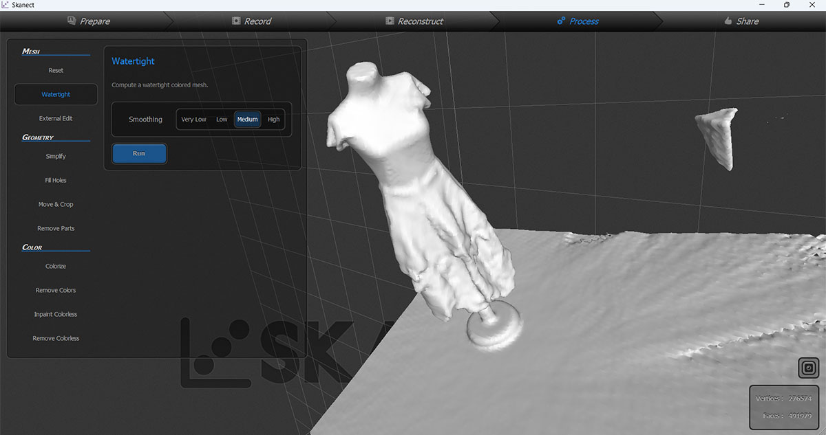
The model can be exported in various formats and it can be used to print it. After scanning the mannequin, I can see that it is essential for the object being scanned not to move. It is also necessary to scan slowly to avoid losing tracking.
Download:
Here you can download de files of the snake