WEEK 2
Computer-aided design
Assignment:
- Model (raster, vector, 2D, 3D, render, animate, simulate, ...) a possible final project, compress your images and videos, and post it on your class page.
This week, I tested some programs developed for 2D and 3D design, focusing on parametric programs with the intention of choosing one to develop the final project. I have experience using Creo because it's the program used at my job, but I'd like to review others as well especially cloud-based versions like Onshape and Fusion 360. I'm quite interested in Onshape because it's from the same manufacturer as Creo.
2D
ProCreate
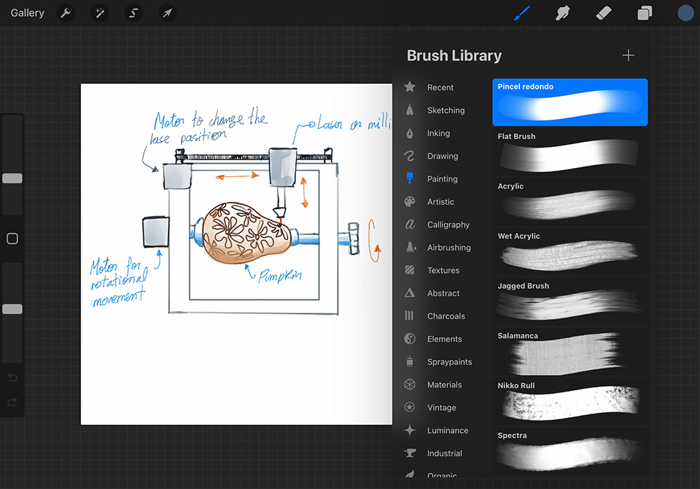
One of the programs I have been testing was Procreate. It is a raster based app with a very user-friendly application with a simple file management system, and one of its best features is its brush library. I have been using this program to create sketches for my final project. It also offers many tools that allow you to create geometric shapes.
Inkscape
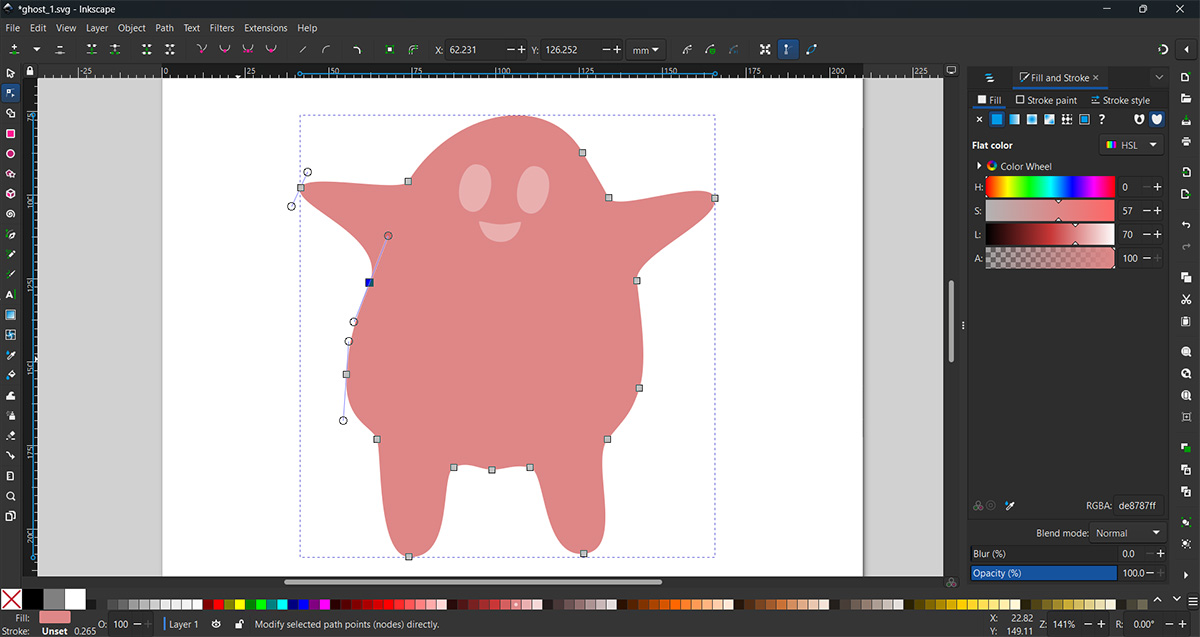
I really enjoyed trying out Inkscape; I hadn't drawn before using the stroke tool, and I found it a bit difficult to control at the beginning, but I believe with more practice, I could learn it well. Inkscape has an interface very similar to Photoshop; the tools are very visible, and it has a very simple and modern interface. It also has various export format options. This time, I made a sort of funny ghost.
3D
Onshape
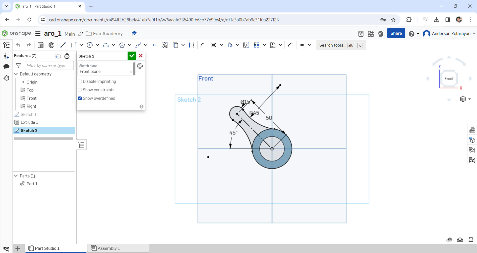
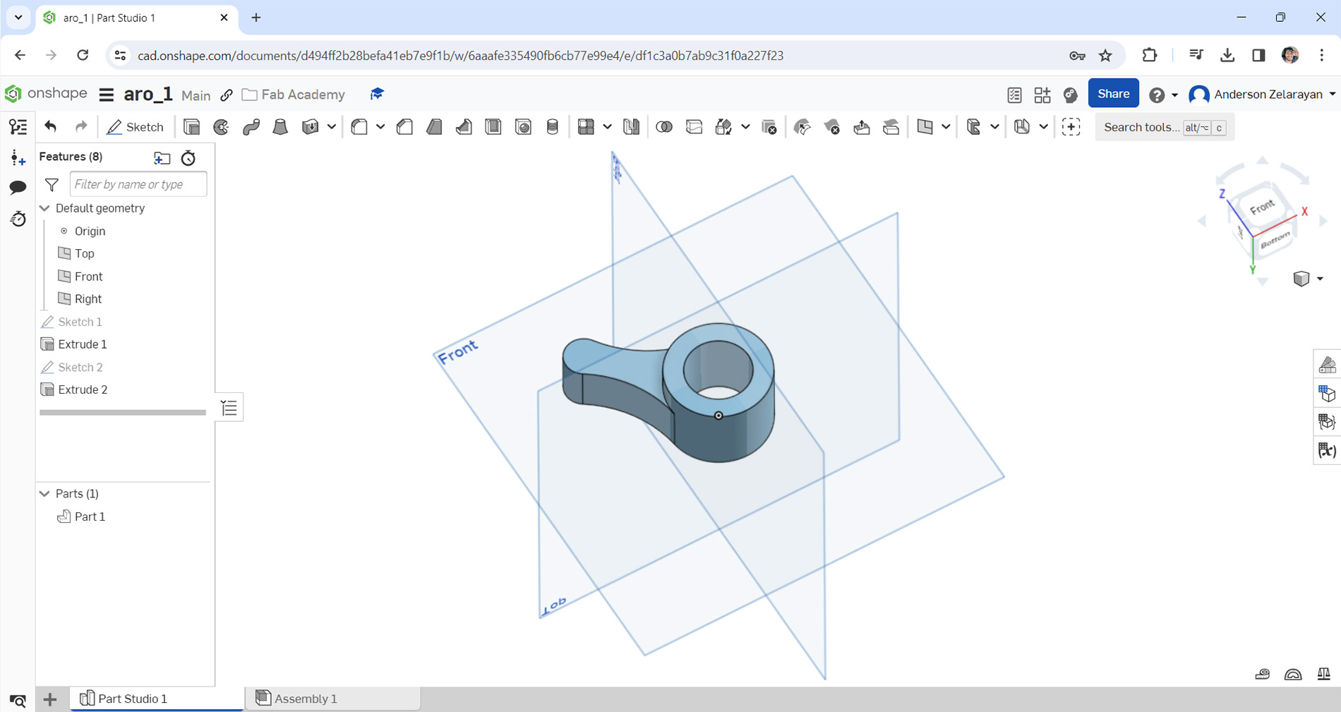
Onshape is from the same manufacturer as Creo. I thought the way to create sketches and other operations would be similar to what I do in Creo, but it's actually more simplified. In this case, I made a solid using only extrusions. Being a web-based app, the huge advantage I see is that you don't need a powerful computer, and you can access your files from anywhere as long as you have a browser.
Fusion 360
I also really liked Fusion 360 I think, same as way as Inventor, it has a very modern interface and the operations are very visible, it is easier to use than Inventor. I also made a part with basic extrusions and revolutions to test it. Additionally, it has an option for freeform modeling, which I find interesting.
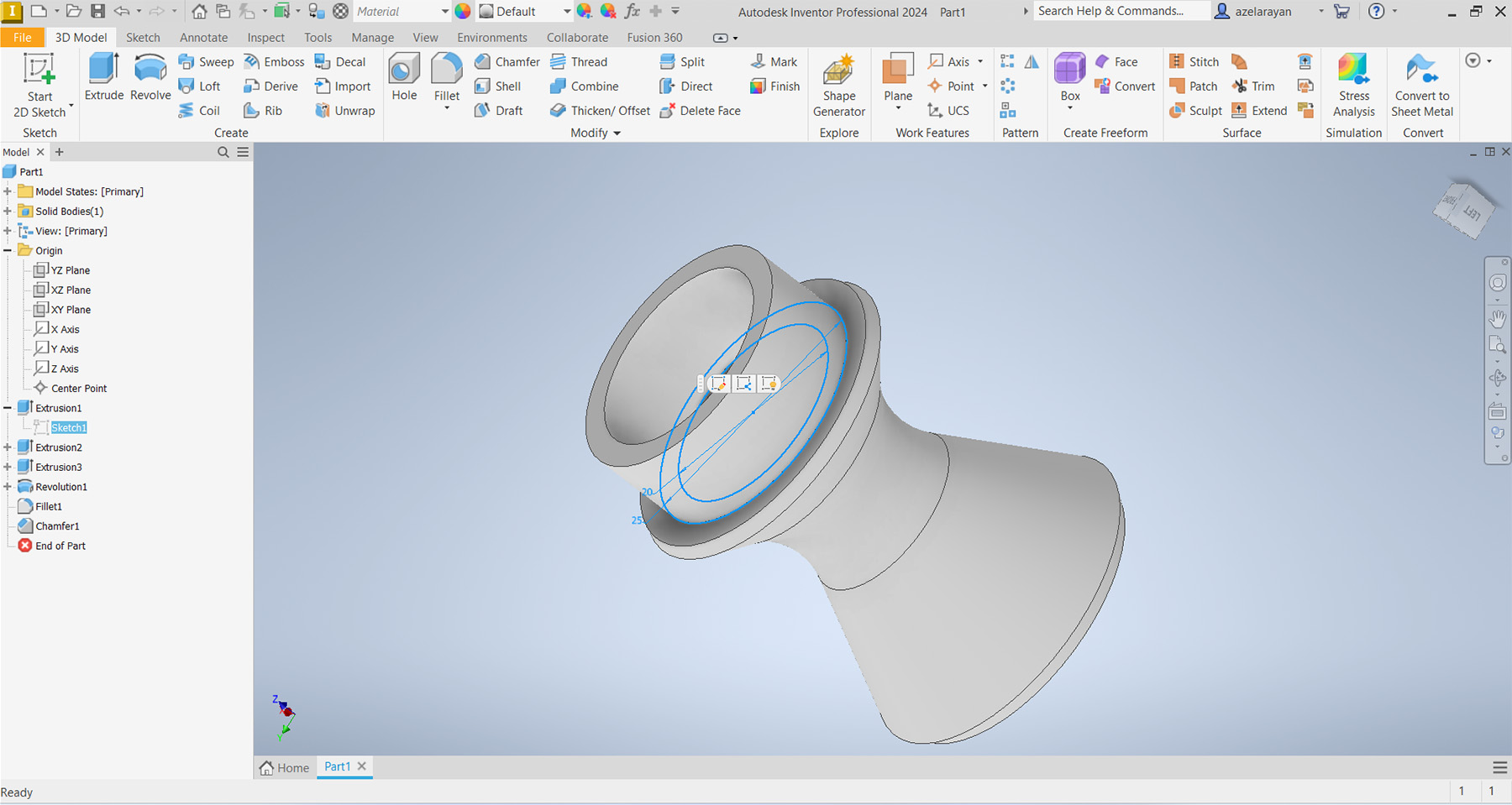
Inventor
Inventor is a program I used when I was in university; it's quite similar to Creo. It's probably the second most used program for me. It features a very modern interface and offers numerous functions for modeling and stress analysis. In Inventor, I created a relatively simple solid using extrusions and revolutions as shown in the image.
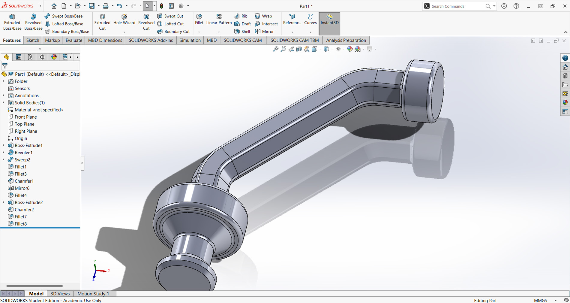
SolidWorks
SolidWorks is a program I used briefly during my time in university, but I didn't learlned it well. It's a powerful tool, so I would like to learn how to use it properly. So, this week, I tried it and modeled a solid with the basic operations. It seemed quite similar to Inventor or Creo. In these programs, you always start by creating an initial sketch, from which you can make various operations like extrusion or revolving, among others. Another common feature among them is the icons used for different operations, the part tree is also very similar.
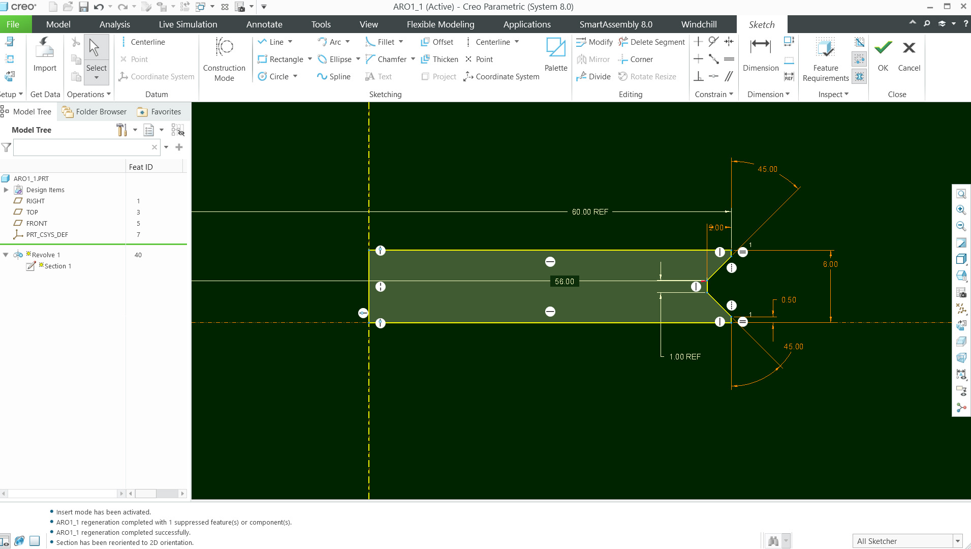
Creo
Creo is one of the programs I am most familiar with because I use it in my job. My team uses the PTC ecosystem to design bottle molds, and we also utilize its servers to host the files we generate. Essentially, what we do is create drawings and models. I believe it's a very powerful program both in 2D and 3D, very similar to Inventor and SolidWorks. However, gear design is more user-friendly in SolidWorks and Inventor. PTC also offers a programming environment called Smart Assembly that helps us automate some of the design process. On the other hand, I think it's a commercial software that isn't cheap, although it does have an educational license option
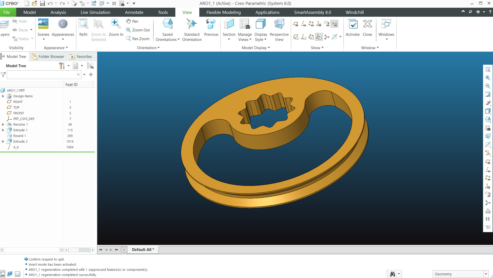
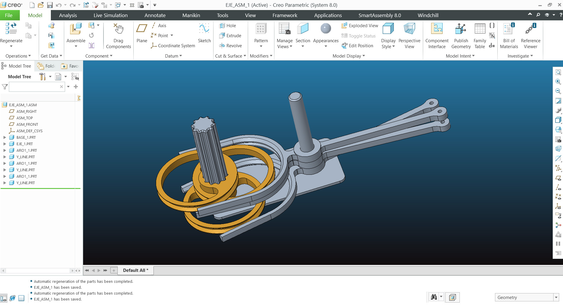
I began modeling some parts of the final project in order to make tests on the mechanism,. The image below shows the progress of the mechanism that provides movement to the body.
The structure I intend to use is similar to the work of Tim Lewis, an artist known for creating metal structure automatas and also JVcreative Who also creates structures, many of which are made using 3D printing. The orange rings will be assembled with an offset of approximately 20 degrees, allowing the Y-shaped bars to have a wavy movement. I haven't tested the movement yet, but I hope it works in that way.
Here you can download de files in STL format of the machanism:
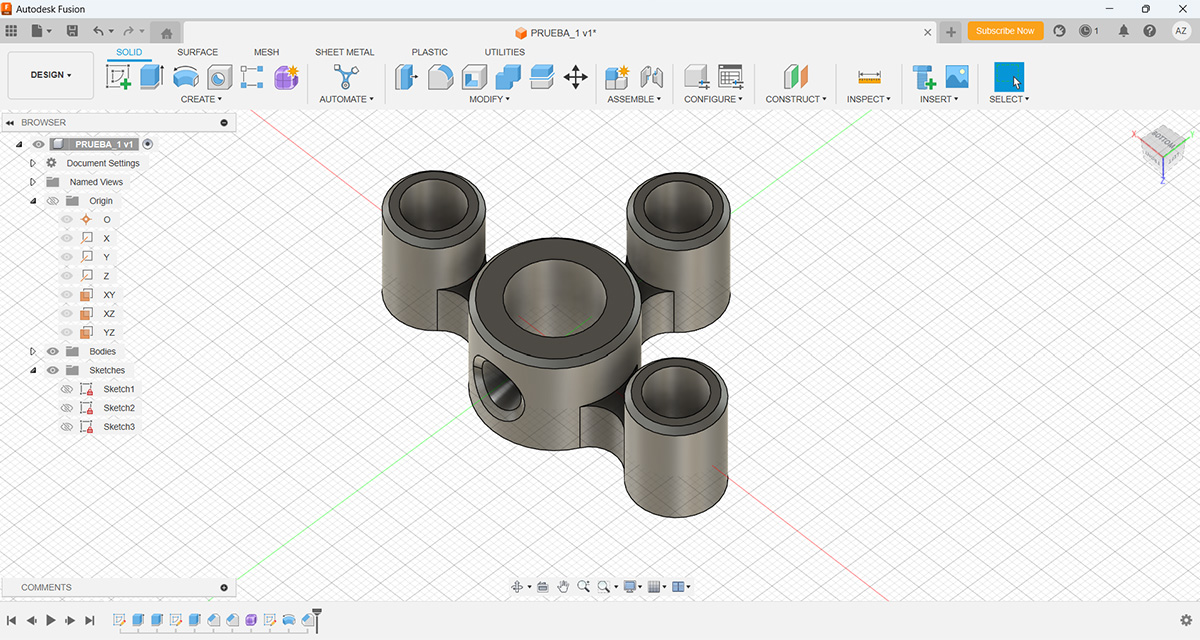
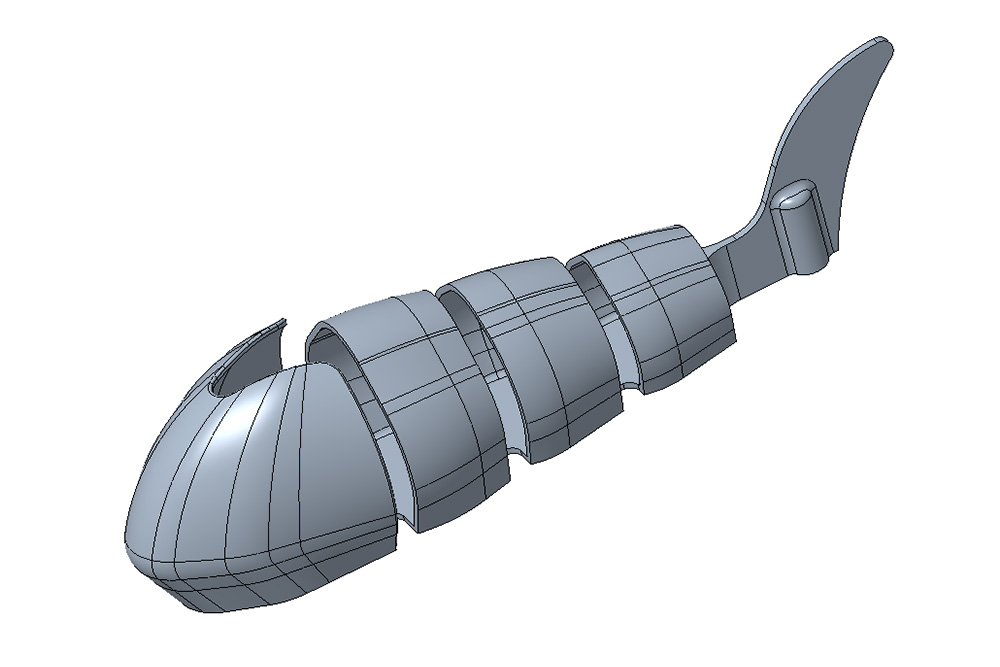
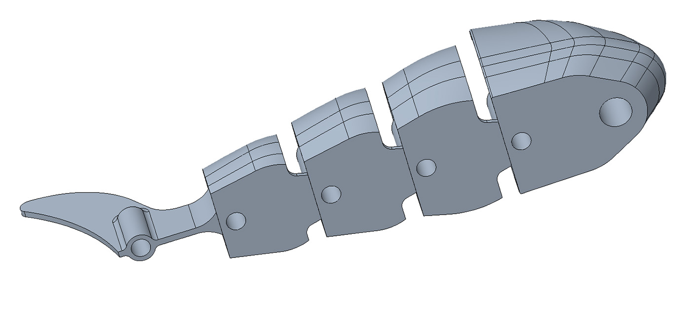
Another important part of the project is the fish's body, which needs to be articulated to allow for a waving motion. So, I made the first versions of the body parts. The following image shows the model, mainly consisting of 6 parts. The idea for now is to produce them using 3D printing. They will be connected with a type of hinge and anchored to the movement mechanism from the bottom.
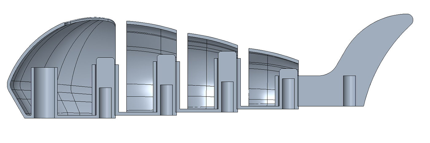
In the following images, you can see in more detail how it will be articulated. Each hole on the bottom part of the body will be used to connect to the body's movement mechanism.
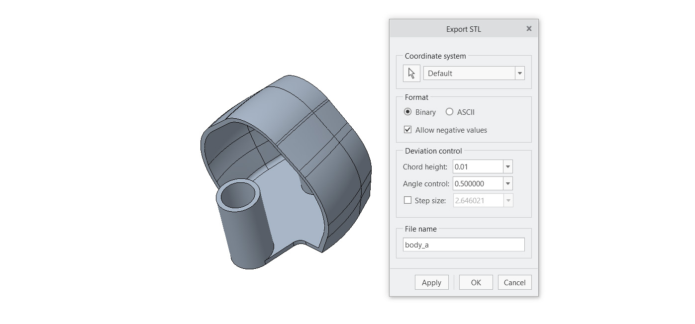
Another thing I tried this week was exporting files in different formats. Below, you can see the options that Creo offers for exporting in .stl format.
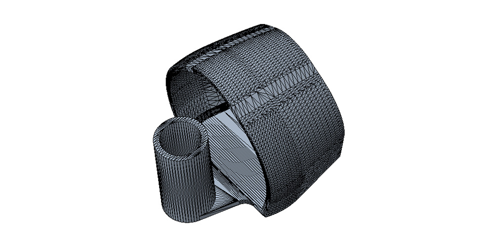
Here you can download de files in STL format of the fish body:
IA
Dall-e
I have experimented with DALL-E to create some images of what will be my final project, and it has produced some very interesting results. Below, I describe the prompt and the resulting image
Prompt:
"I am taking a diploma called Fab Academy, where I will take courses related to digital fabrication. For the end of the course, I have to create a project that applies all these technologies. I am going to give you a description of the project so you can generate an image of it. It involves developing a mechanical sculpture of a Koi fish, simulating the undulating movement of its body as well as the movement it makes to move around, very similar to when it is in a fish tank. The base of the sculpture will be made of wood, approximately 2 centimeters thick, and will be circular, created using a CNC mill. Inside this base, all the mechanisms powered by stepper motors and DC motors will be mounted, plus it will have sensors around it that, when touched, will make the fish move towards the indicated location. The body of the fish will be made of PLA in 3D printing, and the fins out of some flexible plastic. It will have LEDs in the eyes."
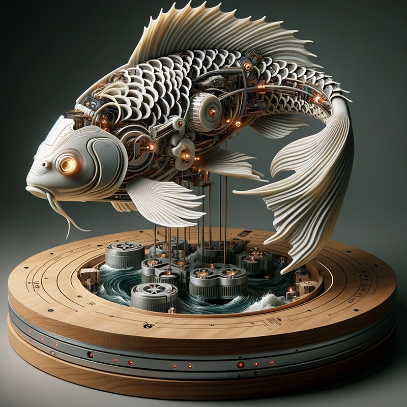
The resulting images are quite realistic and sketch out my idea for the final project. Additionally, after viewing the images, I thought of some additional ideas for the design. DALL·E could help me explore aesthetic options for the project, providing me with inspiration on what its visual appearance could be.
After having tried these programs, I can say the following:
- Fusion 360 and Onshape I think they are easier to use and learn, and also have the advantage of having files online, which facilitates collaboration and access to files from anywhere
- Invetor, SolidWorks and Creo I believe they can be more complex and have a steeper learning curve, but they are quite powerful for engineering projects due to all the operations and functionalities they offer.
- On the other hand, they all have a very similar user interface; they all have the basic 3D modeling operations and also offer quite good simulation tools.
- Dall-e It could be useful for sketching and for generating ideas about the aesthetic part of the project.