WEEK 18
Project Development
Assignment:
Complete your final project tracking your progress.
- What tasks have been completed?
- What tasks remain?
- What has worked? what hasn't?
- What questions need to be resolved?
- what will happen then?
- what have yuo learned?
The presentation day is approaching. Most of the planned activities have been completed. I have also tested the machine's functionality with a basic program, but I still need to test the behavior of the material inside the mold.
Assignment
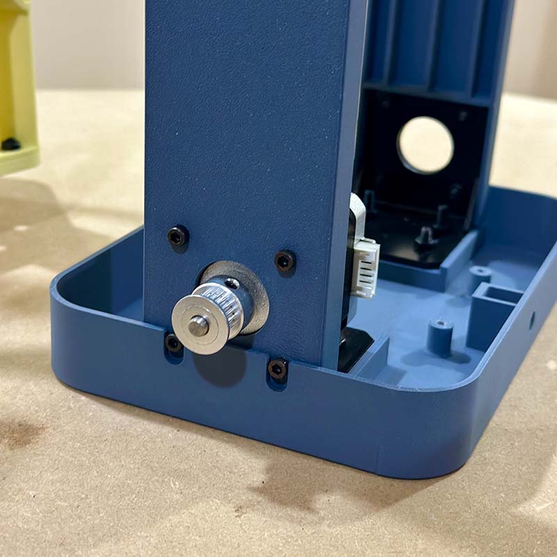
This is the progress of the project.
What tasks have been completed?
At this point, most of the project activities have been completed.
- The mechanical structure is fully assembled, although some parts could be improved.
- All the electronic boards are manufactured and tested.
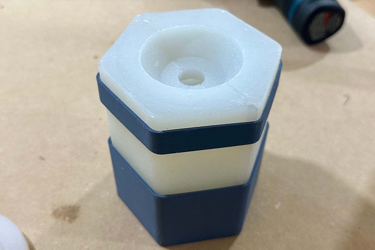
- The silicone mold is made, and I have already tested it without mounting it on the machine.
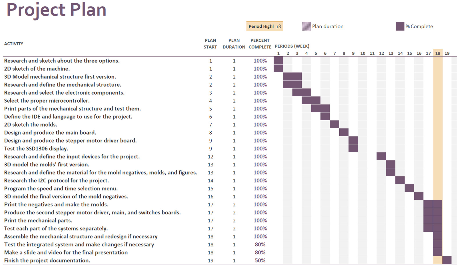
This is the final mechanical structure.
I call the following structure the main structure, It is composed of the base and the side panels. The side panels are attached to the base using 90-degree brackets and M4 screws.:
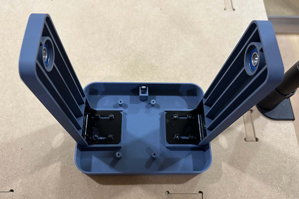
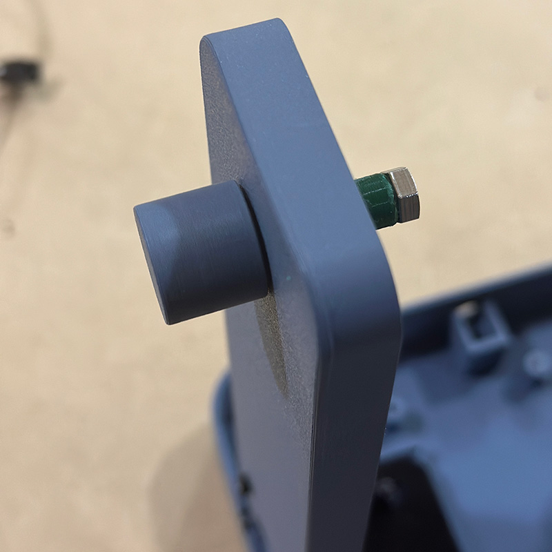
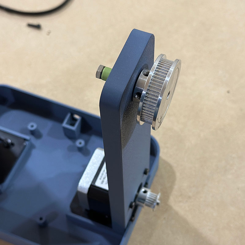
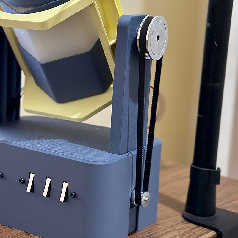
On one of the panels, is assembled the NEMA 17 motor using M3 screws. The motor has a toothed pulley attached to its shaft. Additionally, 608 bearing are placed in the slots of both side panels.
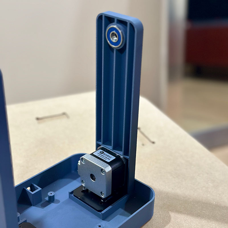
In each side panel, the shafts that will support the secondary block are installed. On the motor side, is placed another toothed pulley as shown.
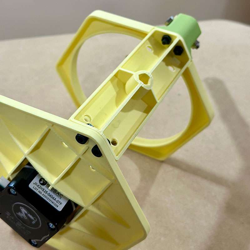
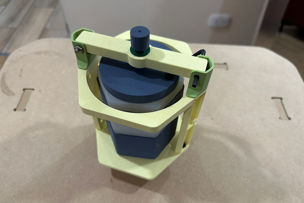
I call the following yellow structure the secondary block, and it is assembled as shown in the following images.
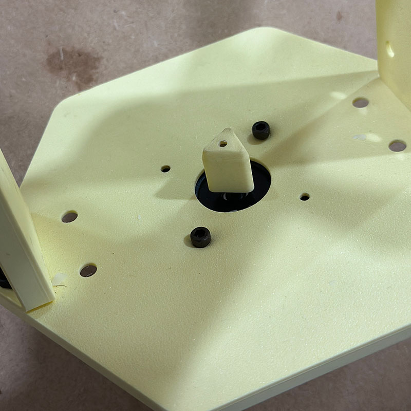
The parts of the secondary block are also joined using M4 screws and their respective nuts. At the base, a NEMA 17 motor is attached, which has a triangular piece on the shaft to transmit power to the mold.
The secondary block has an arm that holds the mold cover, and it is composed of the following parts.
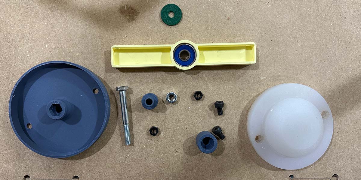
After assembling the parts, the arm looks like this:
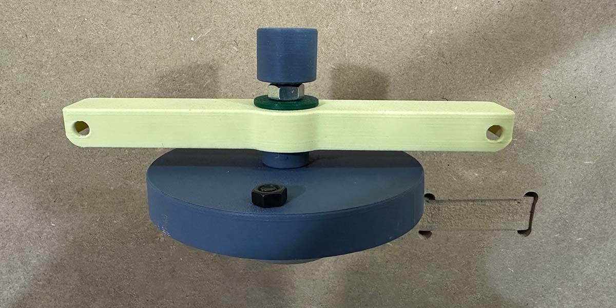
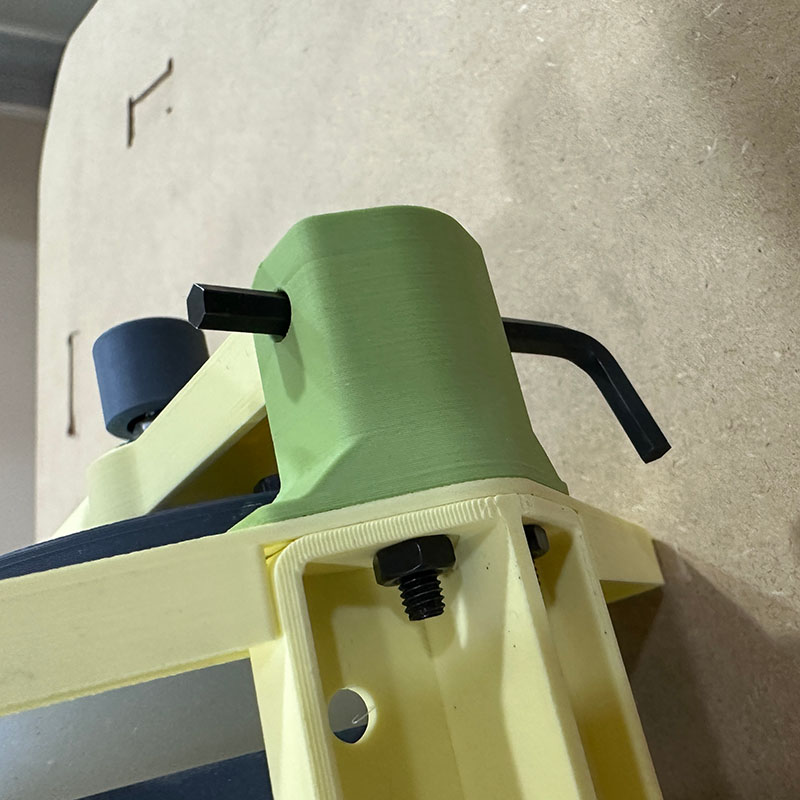
This arm is attached to the structure using an M5 screw with its nut, which also serves as an axle. And to keep the lid closed, I use an Allen key that fits snugly.
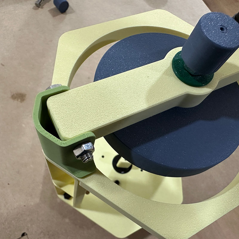
To keep the mold in place and ensure it can be attached to the machine, the parts shown in the image are used.
The secondary block is assembled as follows:
Finally, this is a motion test of the entire mechanical (both the main structure and the secondary block) structure of the machine.
What tasks remain?
- At this point, the machine works as follows: first, motor 1 is activated (rotating the mold 90 degrees), then it stops, and motor 2 is activated (rotating the mold with the selected time and at the selected speed). After motor 2 stops, motor 1 is activated again to return the mold to the initial position. The idea is for motor 1 to continuously move back and forth while motor 2 rotates the mold.
- I still need to test with the wax. I have bought two types of wax; one seems to solidify better, while the other has a sand-like texture and is very fragile.
- Although the mechanical structure is stable and works well, there are some mechanical components, like axles, that could be reprinted to improve the fit.
What has worked? what hasn't?
Fortunately, at this point, most of the system parts are working well. However, it was necessary to make several iterations of the printed parts.
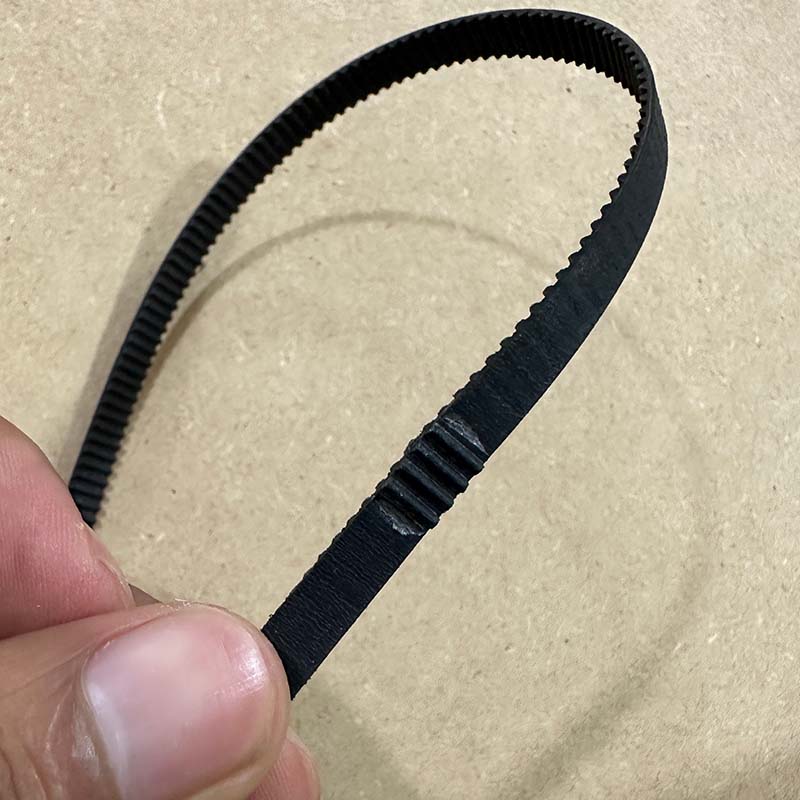
The side panels were also printed multiple times to find the proper tension for the belt. I also tried joining the two ends of the strap using quick-drying glue, but I discarded it because it eventually broke after some time.
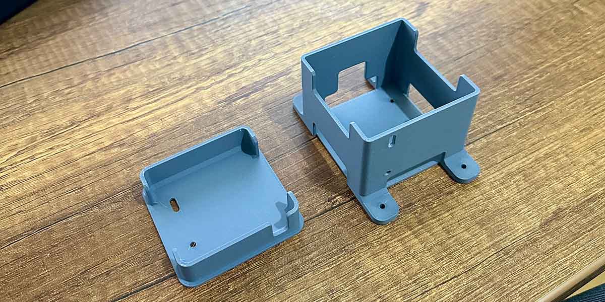
I have designed this box to hold the electronic boards, but when I tried to mount the electronic components, the holes didn't align because I made the mounting holes for the boards by hand using a drill. So, I had to change one of the holes into a slot.
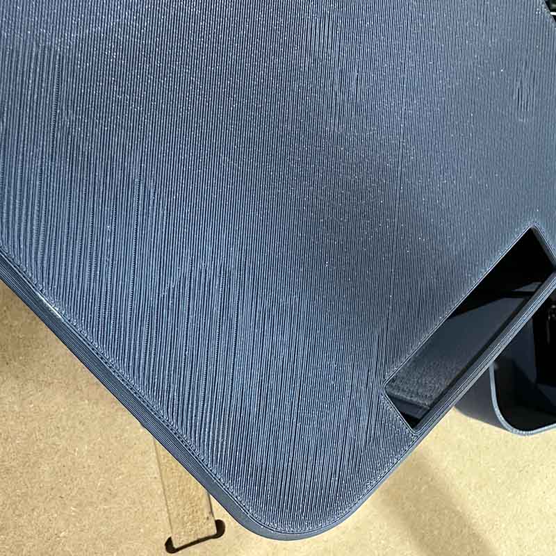
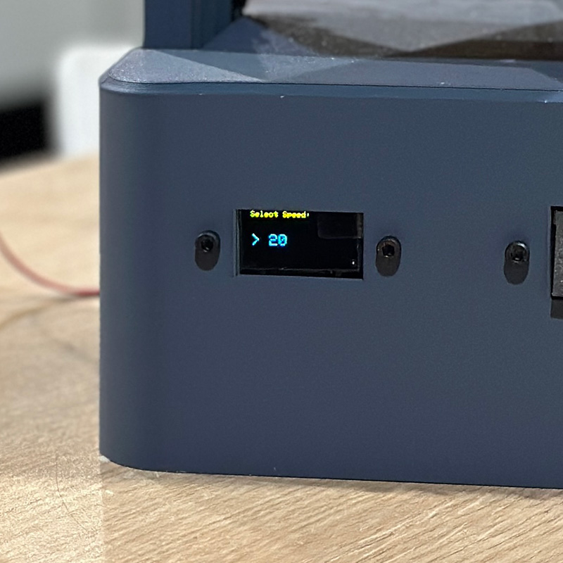
I also had problems with printing the case because it had a rather large surface. In one area, it did not adhere well to the printer bed and deformed a bit. Additionally, in the front part, the slot for the display partially covers the display.
In the electronics part, I didn't have many problems because I used the ones I made in the previous weeks, and they had already been tested.
Although, I had to resolder some times the cables of the power jack socket and the switches holder. because they were the components that were moving a lot during the tests
At one point, I thought my motor drivers were not working because when I tested them with a motor, it only vibrated but didn't turn. The problem was that the motor wires did not follow the standard color code and were not connected correctly to the driver. So, I used a voltmeter to measure continuity and determine which wires belonged to a coil.
I also had an issue with the stepper motors overheating and power loss in the motors, as seen in the last part of the video. I have to replace the 2A power supply with a 3A one, also the current of the drivers was regulated better
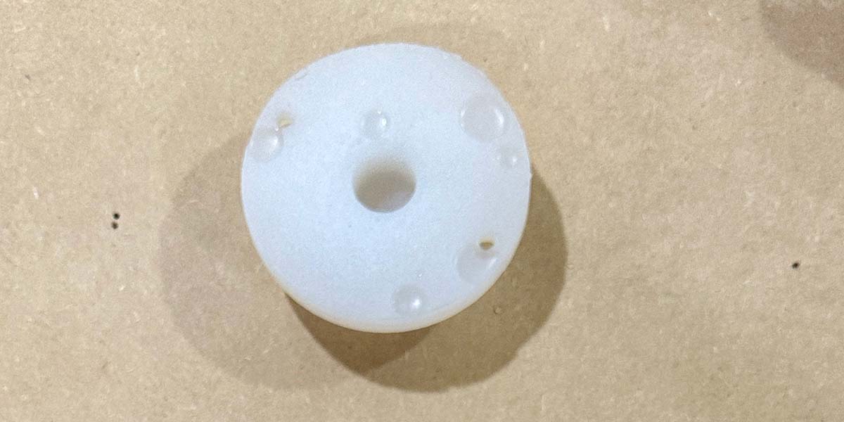
The mold turned out quite well; It only had a few bubbles on the lid, but they were not a import issue because the bubbles are in the part that doesn't make contact with the material.
What questions need to be resolved? & what will happen then?
At this point, I would like to improve the program so that both motors work simultaneously. This will ensure that the figure has a more uniform wall thickness.
I need to conduct tests with the wax. I'm concerned that the solidification time might be too long. It's necessary to have these reference time values to incorporate them into the program.
After loading the program on the Xiao, sometimes it needs to be booted, but the boot button is not easily accessible in my machine, requiring the removal of the case. Making this button more accessible would facilitate the code testing process.
what have yuo learned?
During the design and manufacturing phase of the project, I have learned a lot, mainly about design methodology and making iterations based on testing.
I have learned to design with a greater awareness of the manufacturing process, such as creating models that do not require supports in printing or using shell structures to improve printing time.
Additionally, I have understood the importance of dividing the project into smaller parts to test them independently, so that if something needs improvement, I don't have to change everything. This applies to mechanical parts, electronic boards, and also the program.
I've also realized the importance of planning and completing activities in a timely manner, not leaving things until the last minute, as some issues can arise unexpectedly.