WEEK 16
Wildcard week: Soft Robotics
Assignment:
- Design and produce something with a digital process (incorporating computer-aided design and manufacturing) not covered in another assignment, documenting the requirements that your assignment meets, and including everything necessary to reproduce it. Possibilities include (but are not limited to):
This week we made some actuators for soft robotics. It was a pretty interesting week because we had to run various tests, print our molds, and pour the silicone multiple times, making some improvements. But ultimately, the results were good.
Assignment
SOFT ROBOTICS
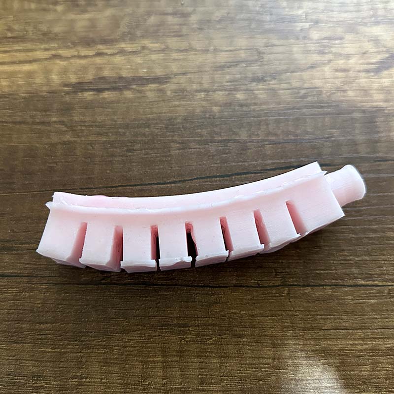
For the development of the assignment, we created an actuator that bends as shown in the image on the left, and also a gripper based on flexible actuators, as seen in the image on the right.
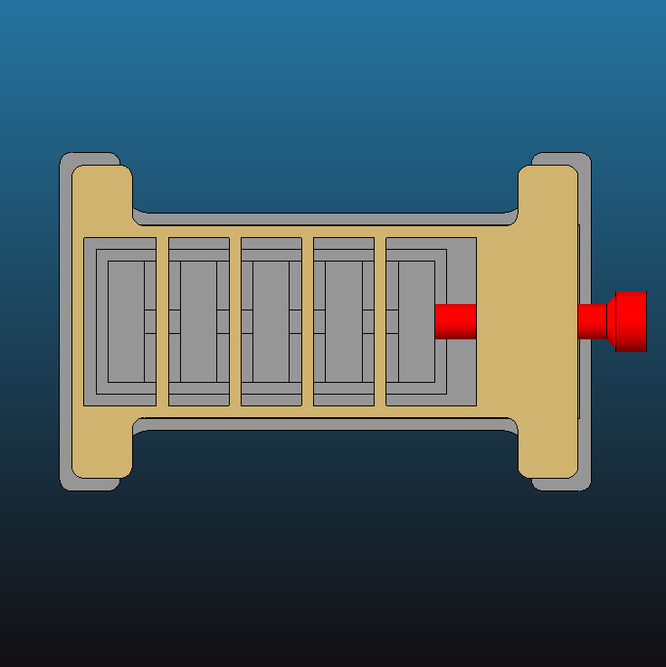
The actuators I made were silicone-based, which required designing the molds. I based my design on examples and models found on the Soft Robotics Toolkit website. In the image on the right, you can see the beige mold they share on their page. However, during testing, the silicone didn't flow well through the cavities, so in my design, I enlarged the spaces and added a connector on one of the ends.
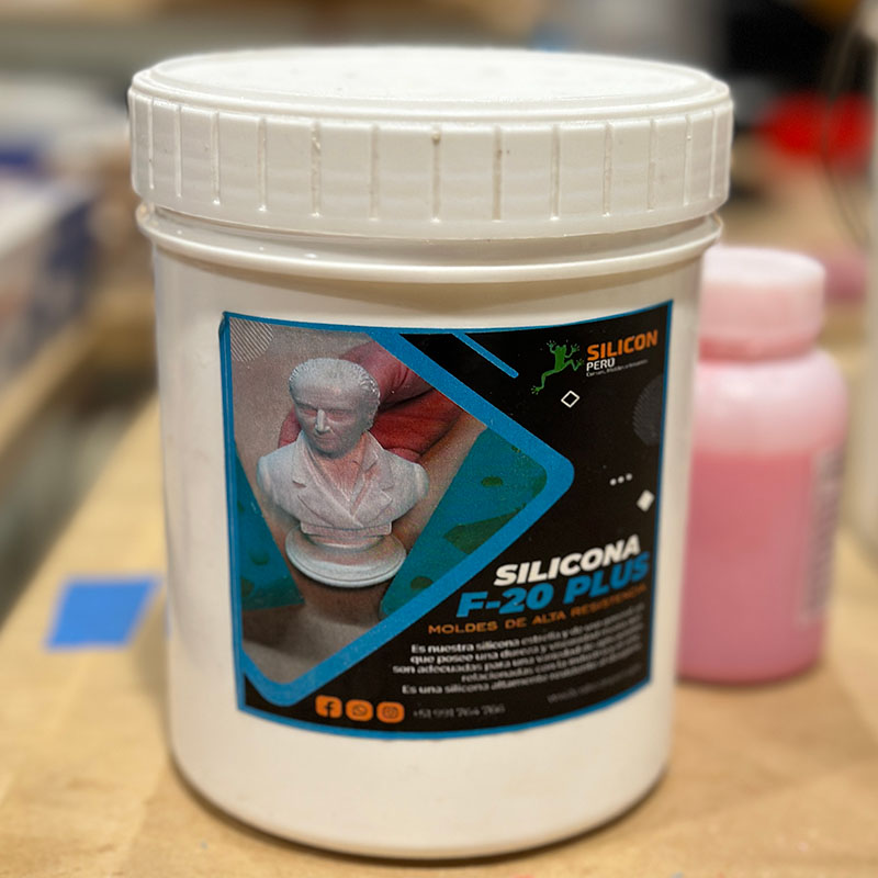
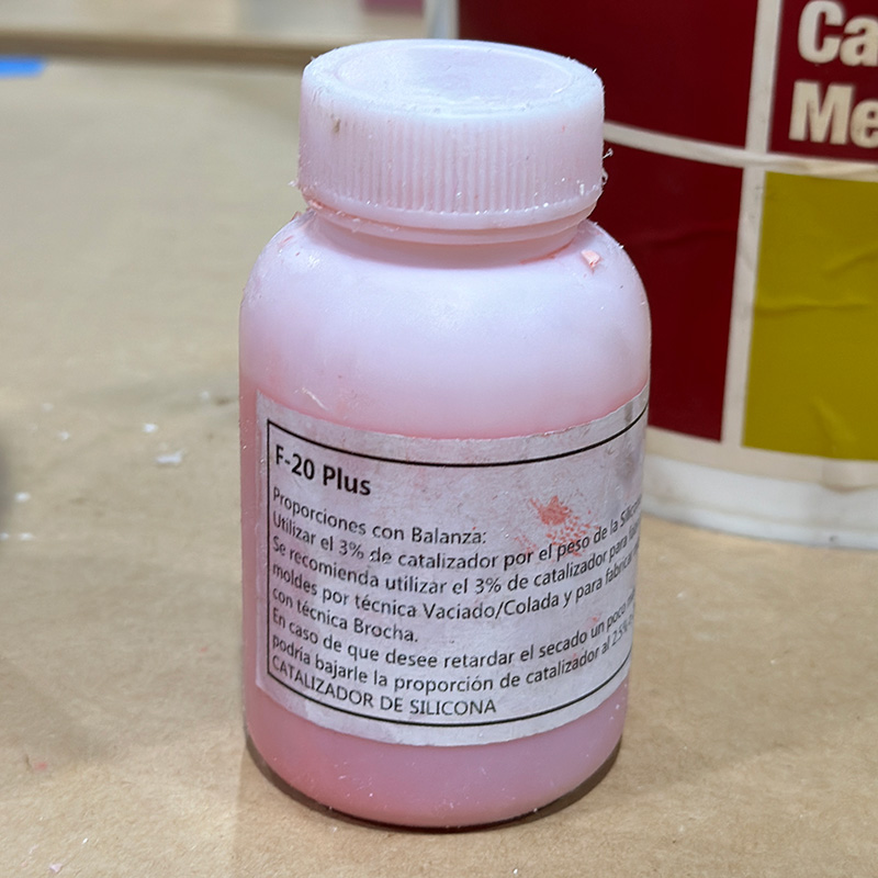
I used RTV (Room Temperature Vulcanization) silicone and its catalyst, the same one I used during the Molding and Casting week. The manufacturer recommends a ratio of 100:3, so we mixed 100 grams of silicone with 3 grams of catalyst for the first actuator.
We also followed the procedure recommended by the Soft Robotics Toolkit website for making the molds:
First, we poured the silicone into the main mold and waited for it to cure.
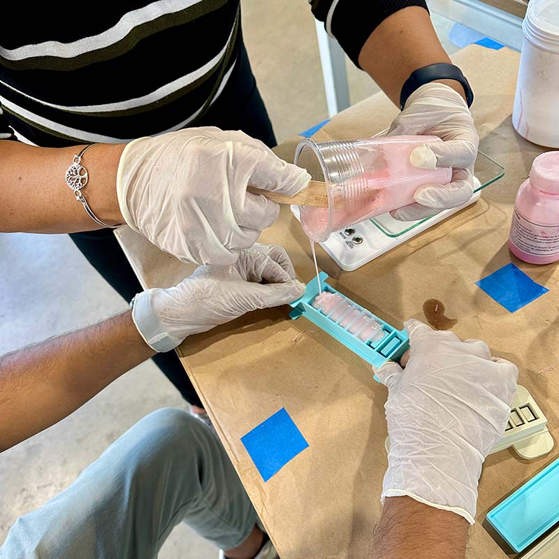
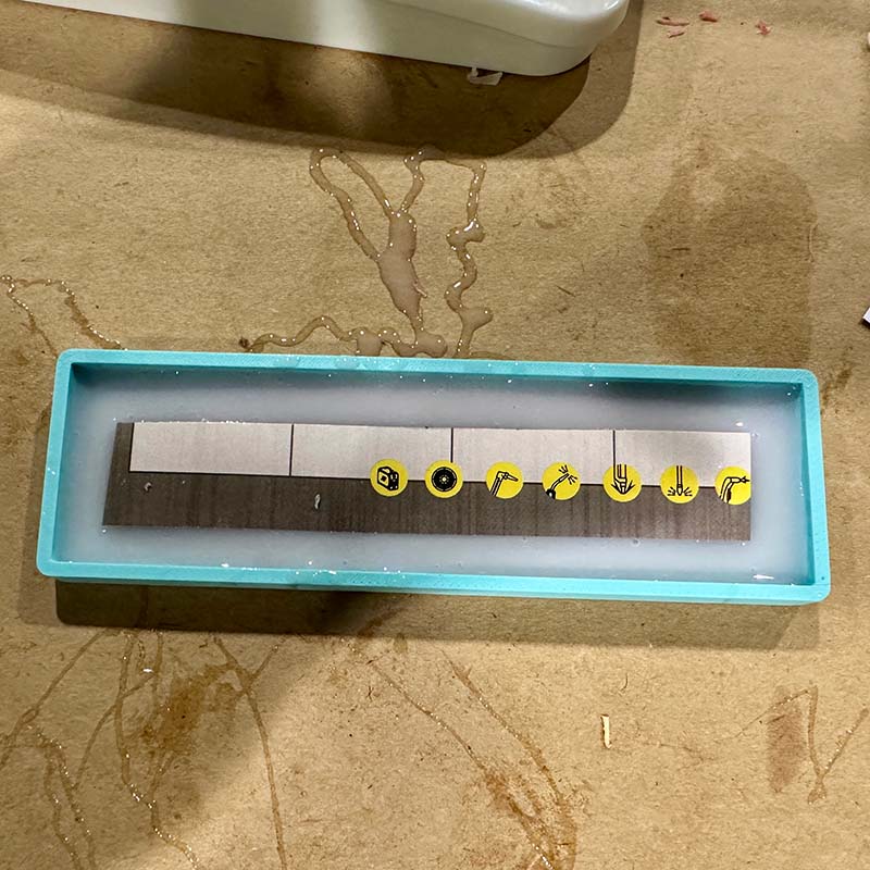
Then, we filled the base mold halfway with silicone and placed a piece of paper on it to serve as the strain-limiting layer. We waited for this to cure. See image on the left.
Next, we filled the rest of the base mold with silicone. This layer of silicone would act as an adhesive between the base and the first part. We then waited for it to cure. See image on the right.
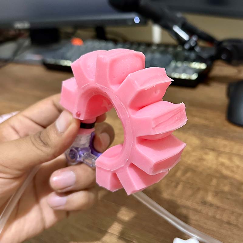
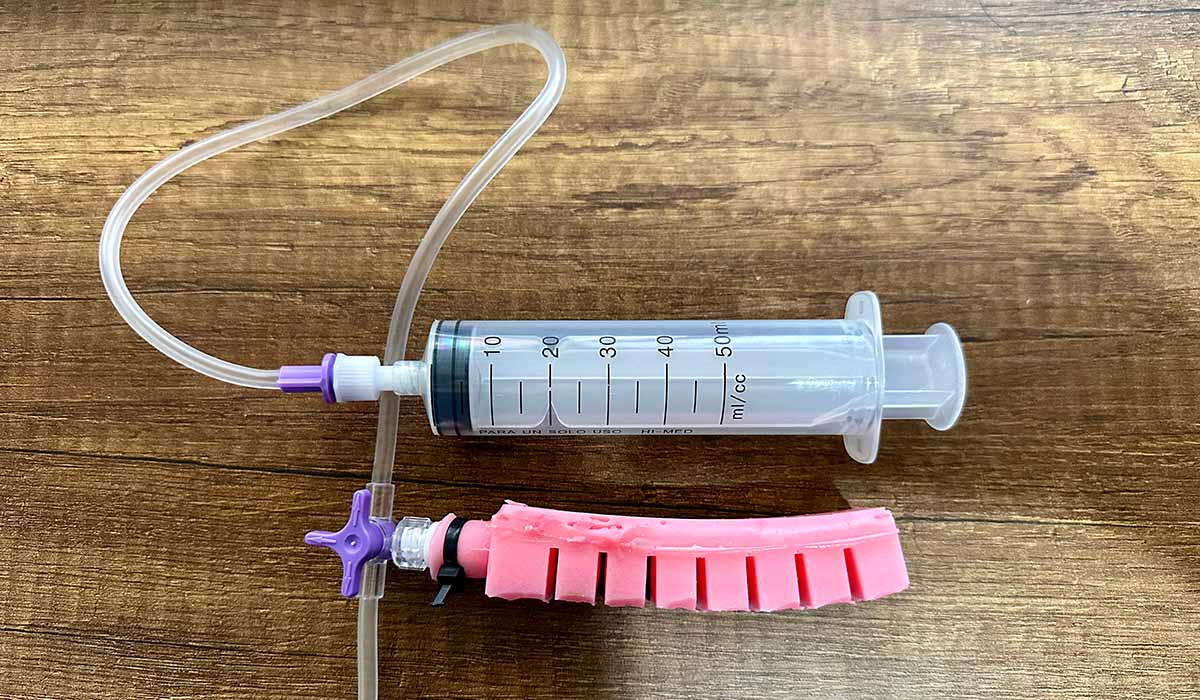
With the mold cured, I made the connections to the other components. To supply the air, I used a 50 ml syringe connected to a hose. We bought these components at a pharmacy. I also used a zip tie to secure the silicone actuator to one end of the hose, as shown in the following image.
In the following video, we can see the operation of the actuator. It bends successfully, but a large bubble also formed in the middle where the paper is located. This is likely because the paper did not adhere to the silicone, and there might be a hole in the silicone layer between the paper and the first part of the mold.
To improve the actuator's performance, I stopped using paper but I made the base thicker. Also, to avoid bubbles, I simplified the cavity design. These changes, along with other improvements, resulted in enhanced movement, as can be seen in the following video.
Other issues that arose were the ears I added to the mold collapsing when demolding. In subsequent designs, I increased the thickness of this part from 2mm to 6mm. I also had problems with bubbles forming, or the silicone not reaching the small cavities at the base of the mold cavity. In later versions, I made the cavity simpler.
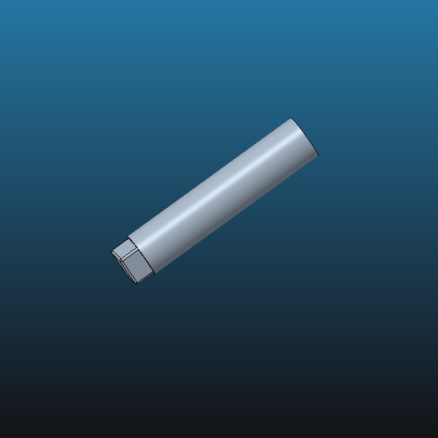
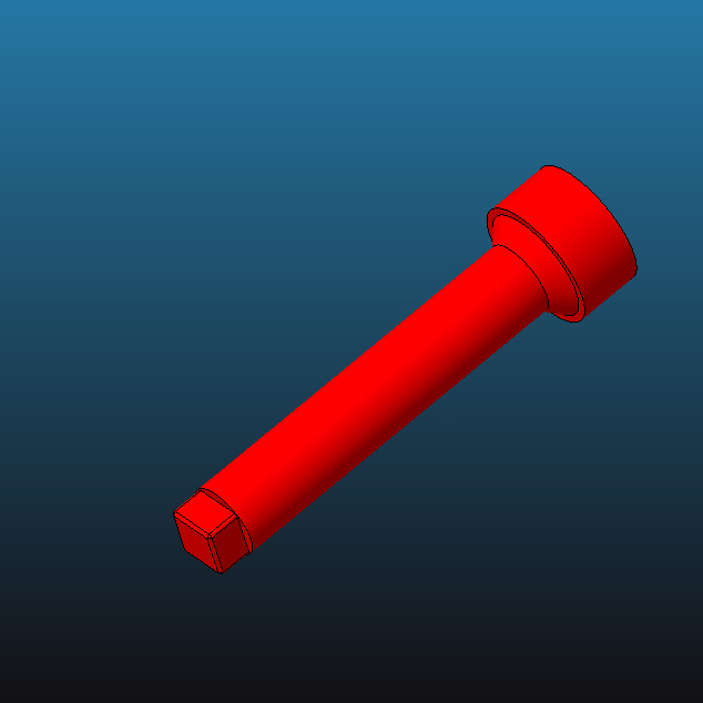
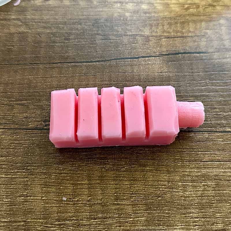
Another change I made was to elongate and add a head to the pin that forms the air inlet of the actuator. This modification makes it easier to remove once the silicone has cured.
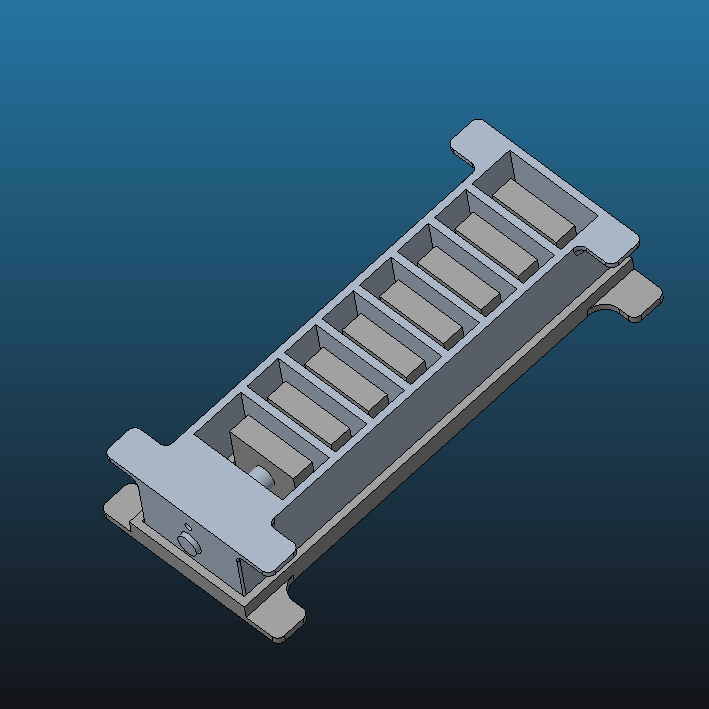
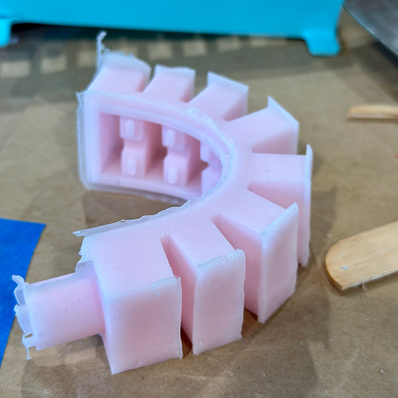
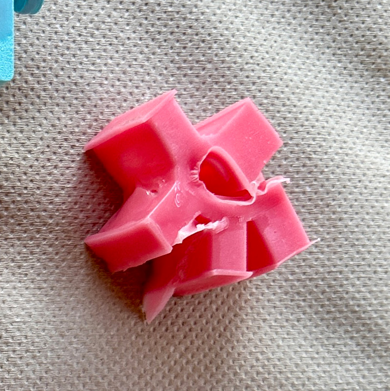
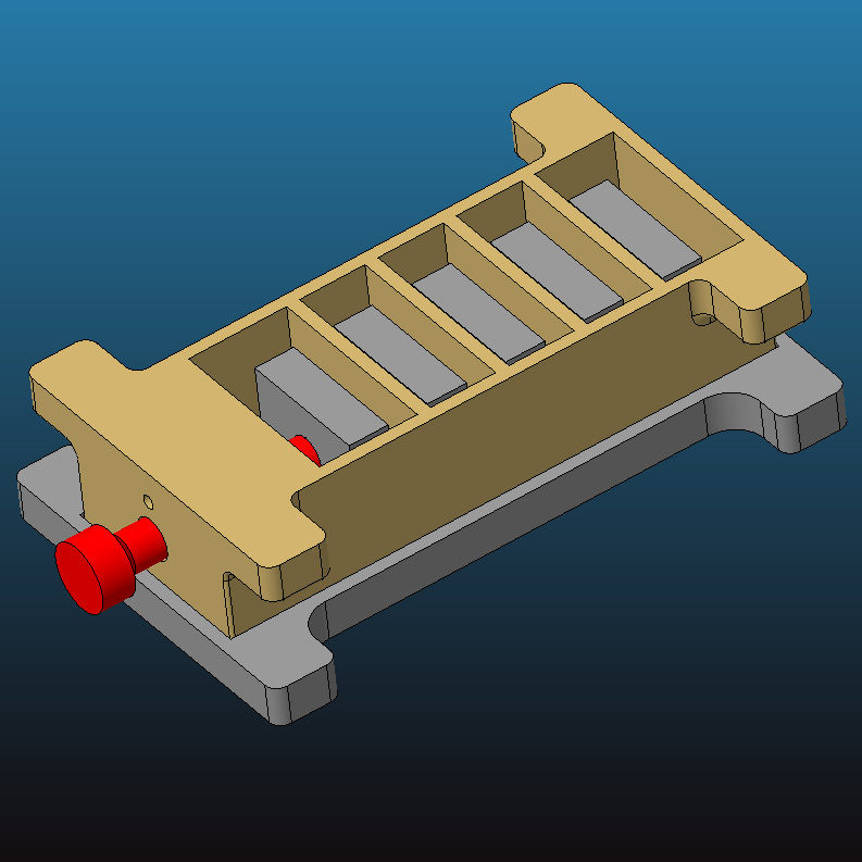
To make the gripper, I created three actuators that have the same shape as the first but are shorter. In the following image, we can see the parts of the first mold I designed with thicker ears and also with the new pin.
But it was also necessary to simplify the cavity, as I mentioned earlier. In the following image, we can see a smaller actuator. On the left is the original, and on the right, the simplified model.
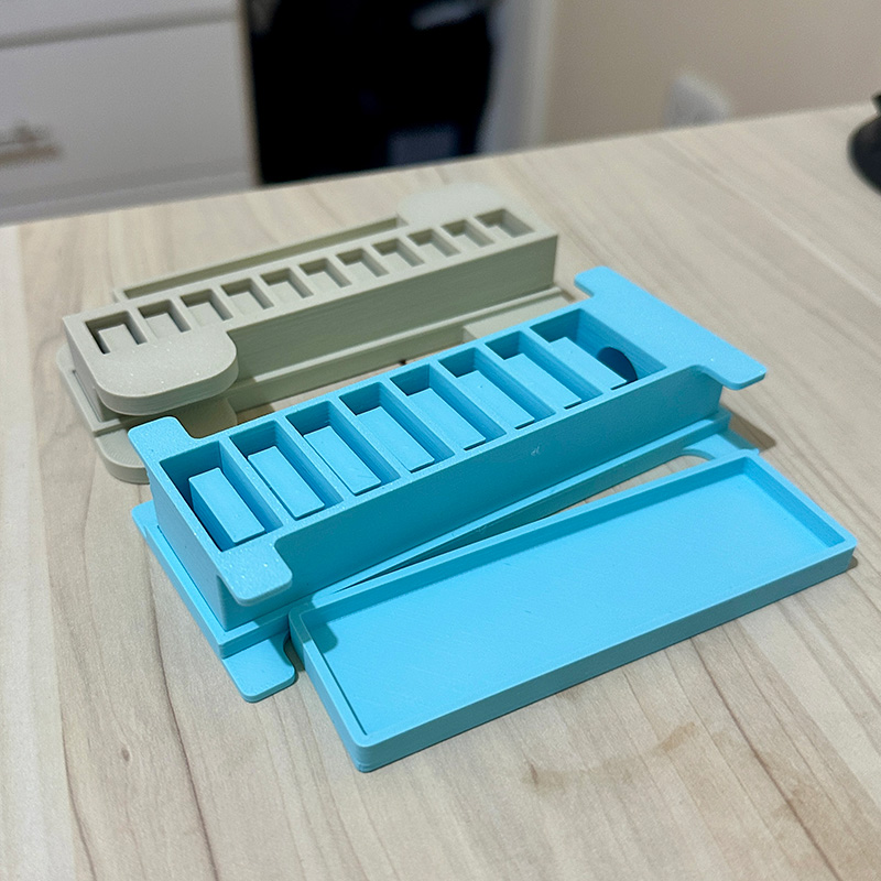
In the following images, we can see the mold of the gripper actuator with the modifications and improvements made and printed. These changes enhanced the demolding process and the performance of the actuators.
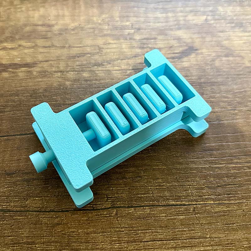
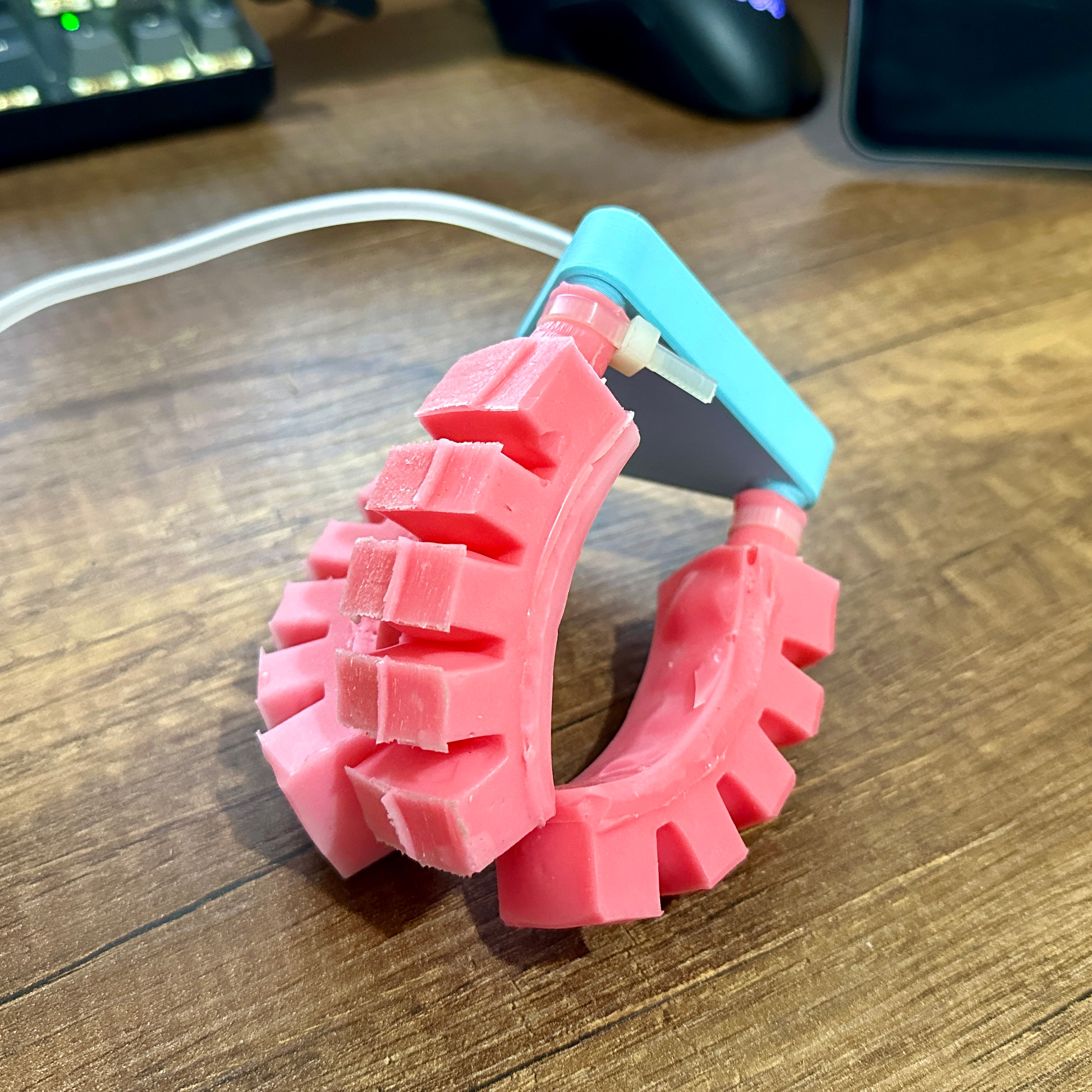
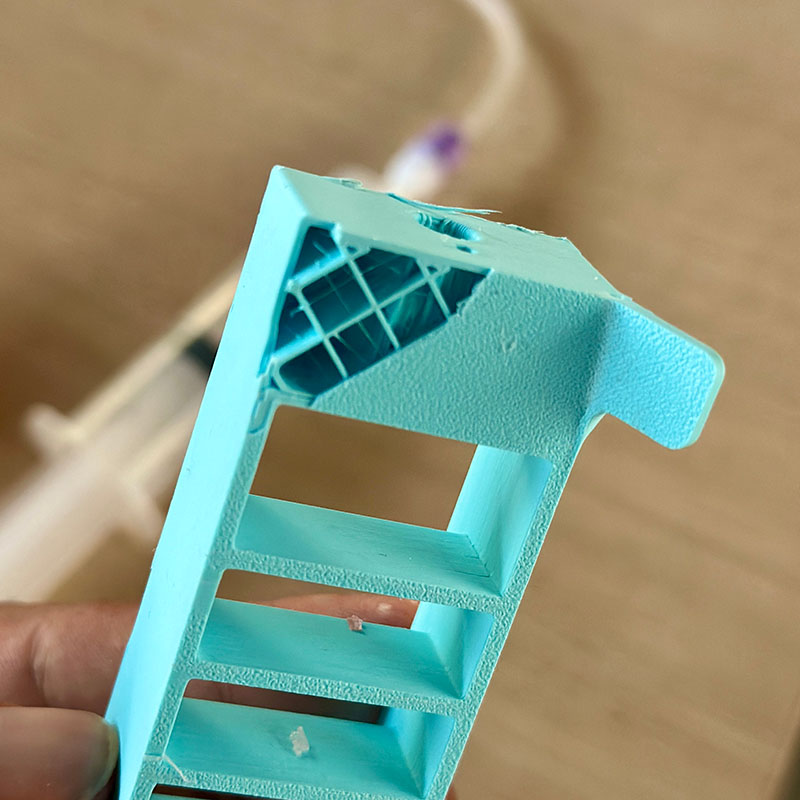
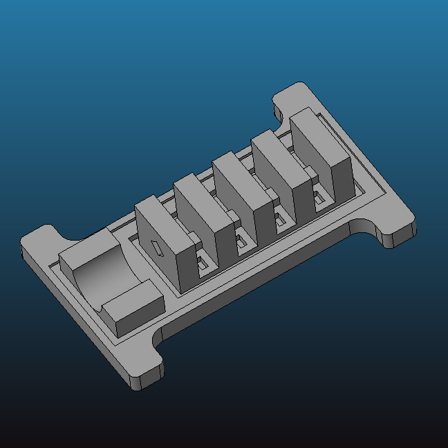
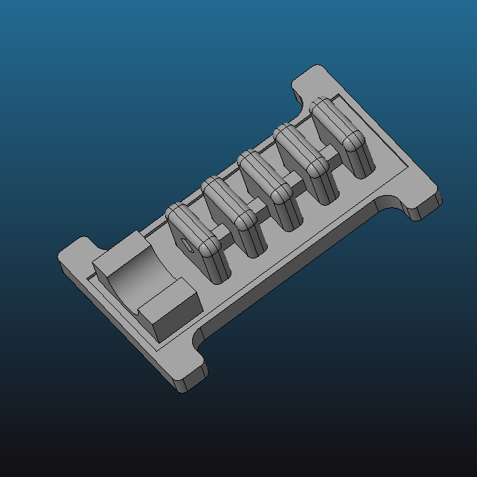
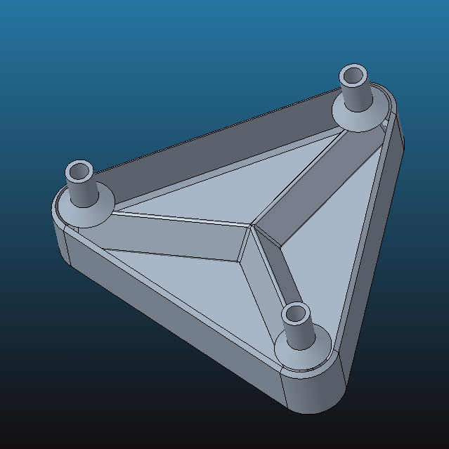
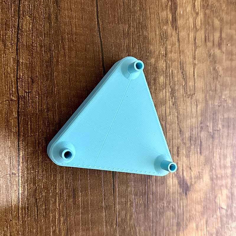
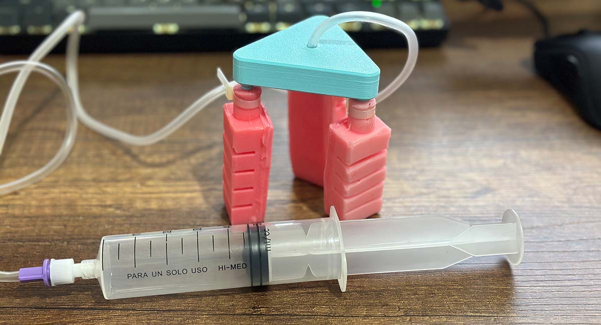
I also designed the following piece that will serve as a structure for the gripper and it will distribute air to the three actuators. This piece has an air inlet with internal cavities to ensure its functionality.
As in the previous test, I used a syringe to inject the air. In this case, I attached the manifold to the air distributor using a quick-drying glue.
In the following video, you can see the result of the gripper's movement.
I also tested the gripper by lifting a light load.
Download:
Here you can download de printable parts of the mould:
- molde_1a.stl
- molde_1b.stl
- base_1.stl
- molde_2a.stl
- molde_2b.stl
- molde_3a.stl
- molde_3b.stl
- base_2-3.stl
- flex_1.stl
- pin_1.stl
- pin_1.stl