WEEK 14
Networking and communications
Group Assignment:
- Send a message between two projects.
Individual Assignment:
- design, build, and connect wired or wireless node(s) with network or bus addresses and local input &/or output device(s)
This week was quite interesting because we learned about some communication protocols, both wired such as SPI and I2C, and wireless like Bluetooth and WiFi, among others. It also made me think about the possibilities that remote device control opens up.
Group Assignment
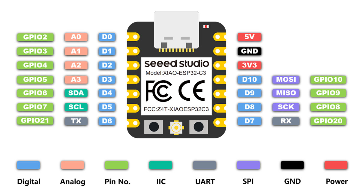
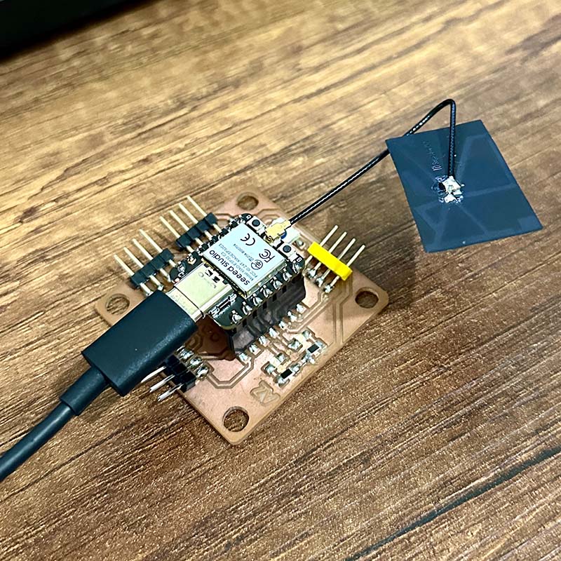
In the group part this week, we worked with wireless communication. For this, we used the Xiao ESP32C3 microcontroller, which has both WiFi and Bluetooth modules. It also has the same pin configuration as the Xiao RP2040, which allowed us to use the same board we designed during Electronics Production week.
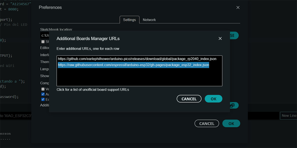
It was necessary to make some configurations to the Arduino IDE. We followed the step-by-step instructions from the Seeed Studio WIKI page.
The first thing we did was to add the following board manager URL for the ESP32. This is added from File > Preferences: https://raw.githubusercontent.com/espressif/arduino-esp32/gh-pages/package_esp32_index.json
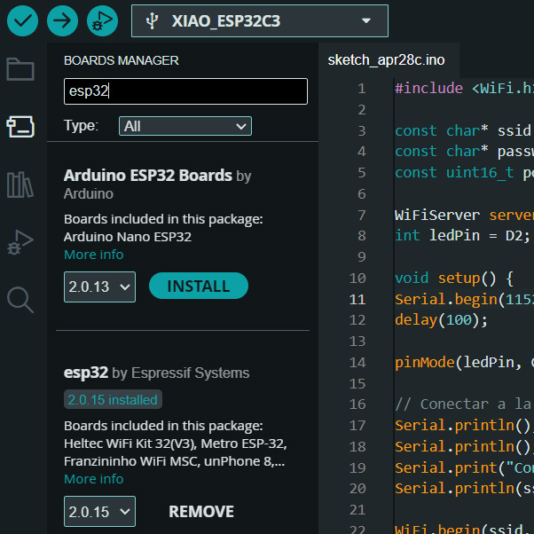
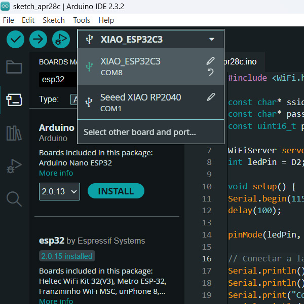
Next, we installed the ESP32 board manager by Espressif Systems, and then selected the appropriate port.
Our goal was to establish WiFi communication between two boards, each mounted with an ESP32C3, and then turn on an LED on one of the boards by pressing a button located on the other board.
After researching and consulting with ChatGPT, we understood that one of the boards needed to function as a server and the other as a client. Additionally, both boards had to connect to a network. This network could be an existing one, or one of the boards could be used as an access point. We decided to connect both boards to a mobile phone's network.
The following is the server code:
//Server
#include <WiFi.h>
const char* ssid = "iPhone de Anderson"; //WiFi name
const char* password = "A1234567"; // WiFi password
const uint16_t port = 8080; // Servidor port
WiFiServer server(port);
int ledPin = D2; // Pin del LED
void setup() {
Serial.begin(115200);
delay(100);
pinMode(ledPin, OUTPUT);
// Connecting to WiFi
Serial.println();
Serial.println();
Serial.print("Conectando a ");
Serial.println(ssid);
WiFi.begin(ssid, password);
while (WiFi.status() != WL_CONNECTED) {
delay(500);
Serial.print(".");
}
Serial.println("");
Serial.println("WiFi conectado");
Serial.println("Dirección IP: ");
Serial.println(WiFi.localIP());
// Server begin
server.begin();
Serial.println("Servidor iniciado");
}
void loop() {
// Waiting a client
WiFiClient client = server.available();
if (client) {
Serial.println("Nuevo cliente conectado");
// Waiting data from client
while (client.connected()) {
if (client.available()) {
// Reding client data
String request = client.readStringUntil('\r');
Serial.println("Mensaje recibido: " + request);
// Turn the led on or turn the led off
if (request.startsWith("ON")) {
digitalWrite(ledPin, HIGH);
} else if (request.startsWith("OFF")) {
digitalWrite(ledPin, LOW);
}
break;
}
}
// Cerrar la conexión con el cliente
client.stop();
Serial.println("Cliente desconectado");
}
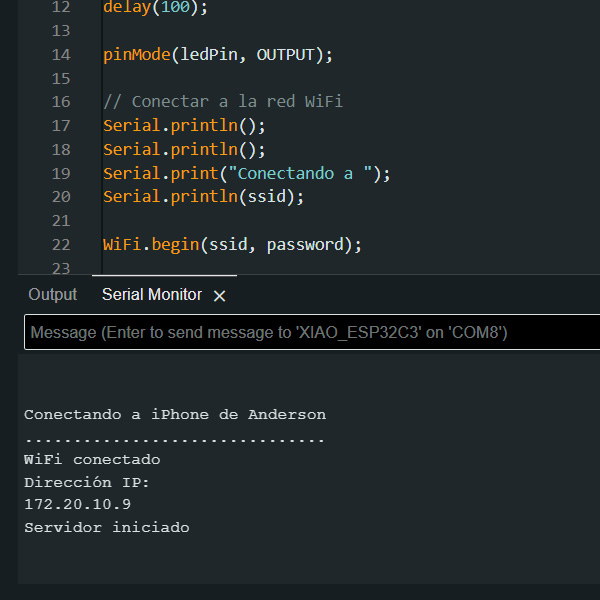
}After loading the code onto the server, it assigns an IP to the device. We'll use that number to connect from the client card.
The following is the code that is loaded onto the client, using the IP and port established in the previous steps.
//Client
#include <WiFi.h>

const char* ssid = "iPhone de Anderson";     // WiFi name
const char* password = "A1234567"; // WiFi password
const char* host = "172.20.10.9"; // IP address of the server
const uint16_t port = 8080;        // Server port

const int buttonPin = D1; // Switch pin
bool buttonState = false; // Switch state
bool lastButtonState = false; // Last state of the switch
WiFiClient client;

void setup() {
Serial.begin(115200);
delay(100);

pinMode(buttonPin, INPUT);

// Connecting to WiFi
Serial.println();
Serial.println();
Serial.print("Conectando a ");
Serial.println(ssid);

WiFi.begin(ssid, password);

while (WiFi.status() != WL_CONNECTED) {
delay(500);
Serial.print(".");
}

Serial.println("");
Serial.println("WiFi conectado");
Serial.println("Dirección IP: ");
Serial.println(WiFi.localIP());
}

void loop() {
// Leer estado del pulsador
buttonState = digitalRead(buttonPin);

// If the state changed
if (buttonState != lastButtonState) {
if (buttonState == LOW) {
// Send message to server to turn on the LED
if (client.connect(host, port)) {
Serial.println("Enviando mensaje al servidor para encender el LED");
client.print("OFF");
client.stop();
} else {
Serial.println("Error al conectar con el servidor");
}
} else {
// Send message to server to turn off LED
if (client.connect(host, port)) {
Serial.println("Enviando mensaje al servidor para apagar el LED");
client.print("ON");
client.stop();
} else {
Serial.println("Error al conectar con el servidor");
}
}
lastButtonState = buttonState;
}
}
This is the result of the tests; we managed to turn on the LED, although there is a delay of half second approximately.
Individual Assignment
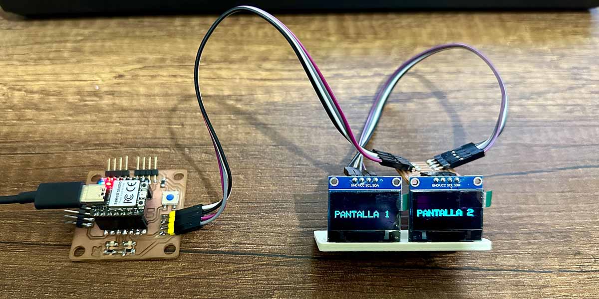
TWO SCREENS WITH I2C
For this week's individual project, I wanted to control two SSD1306 displays connected in series via I2C. This protocol uses four communication cables, one of which is ground and another is for power.
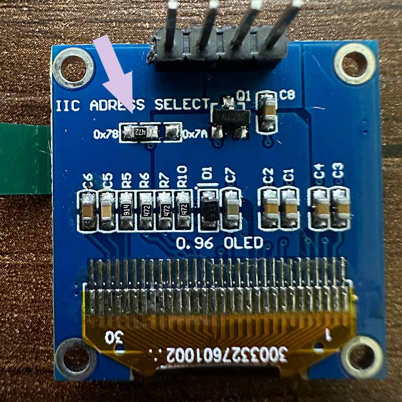
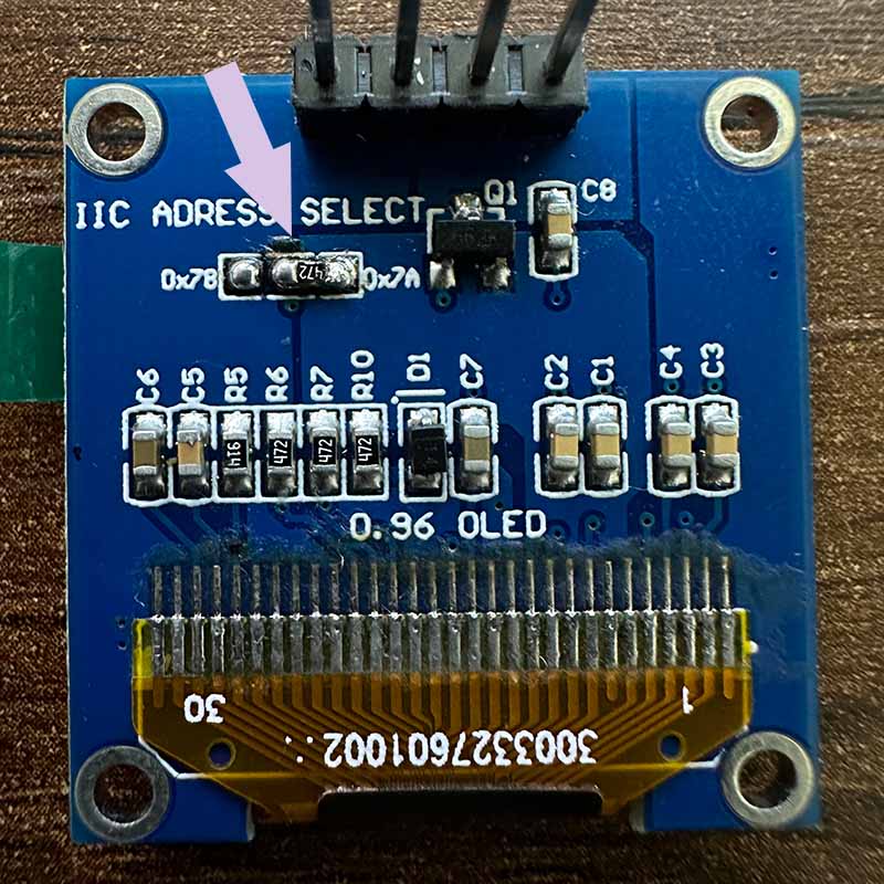
To establish communication with a specific device on the network, is used an address. The SSD1306 displays we have in the lab are factory set to the address 0x3C, but it is possible to change it to 0X3D by repositioning a resistor on the back. Therefore, it was necessary to desolder and resolder this resistor. Since it only has two positions, only two screens of this type can be connected to the network.
Use the following code to write something specific on each screen:
#include <Wire.h>
#include <Adafruit_GFX.h>
#include <Adafruit_SSD1306.h>

#define SCREEN_WIDTH 128
#define SCREEN_HEIGHT 64
#define OLED_RESET -1

// I2C address of the SSD1306 displays
#define OLED_ADDR_1 0x3C
#define OLED_ADDR_2 0x3D

// Adafruit_SSD1306 objects for each display
Adafruit_SSD1306 display1(SCREEN_WIDTH, SCREEN_HEIGHT, &Wire, OLED_RESET, OLED_ADDR_1);
Adafruit_SSD1306 display2(SCREEN_WIDTH, SCREEN_HEIGHT, &Wire, OLED_RESET, OLED_ADDR_2);

void setup() {

display1.begin(SSD1306_SWITCHCAPVCC, OLED_ADDR_1);
display1.clearDisplay();
display1.setTextColor(WHITE);

display2.begin(SSD1306_SWITCHCAPVCC, OLED_ADDR_2);
display2.clearDisplay();
display2.setTextColor(WHITE);

delay(2000);
}

void loop() {

display1.clearDisplay();
display1.setTextSize(2);
display1.setCursor(0, 30);
display1.print("PANTALLA 1");
display1.display();

display2.clearDisplay();
display2.setTextSize(2);
display2.setCursor(0, 28);
display2.print("PANTALLA 2");
display2.display();

delay(500);
}
Here is the result:
DISPLAYING IMAGES IN THE SSD1306
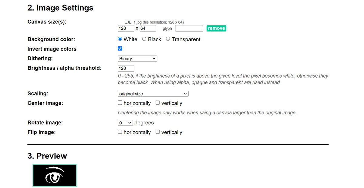
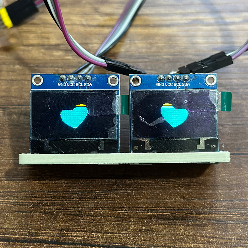
The next test I conducted was to display an image on the SSD1306. For this, I used Image2cpp, which is a website that allows you to convert an image to a bitmap. It also provides the image as a matrix in Arduino code. What I did was crop the image of an eye to fit the screen size of 128 x 64 pixels. To get the image for the other screen, I used the option to flip the image.
The website delivers the image in the following format:
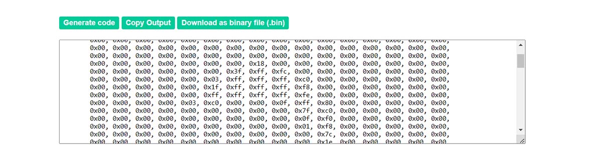
I used the following program to display an eye on each screen: The result seems good, although it is somewhat slow.
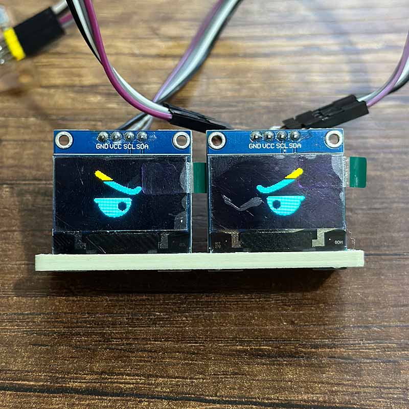
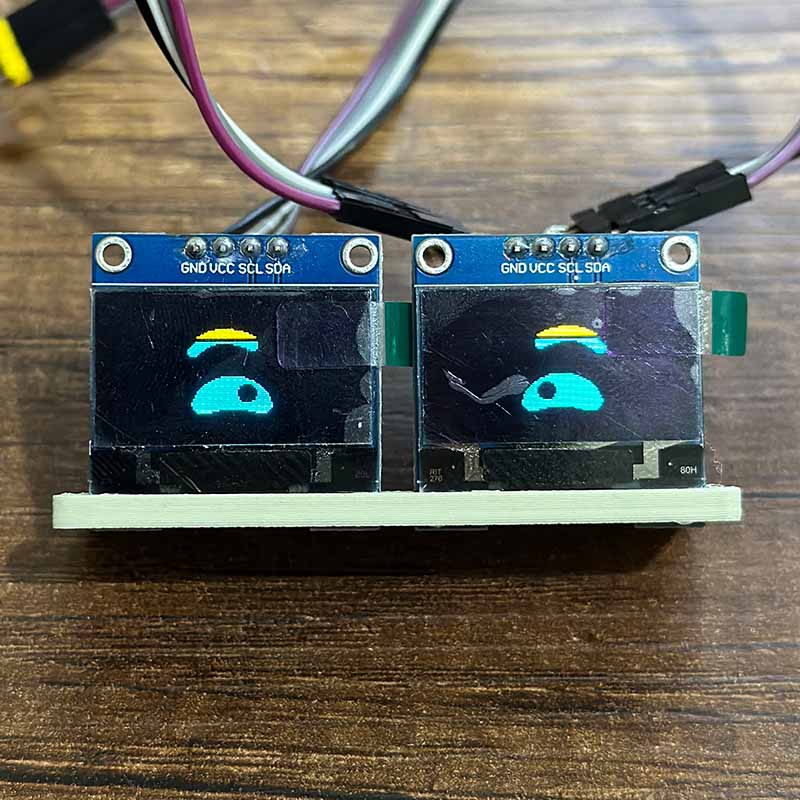
eyes_diplay.txtA program very similar to the previous one is this one, which displays two eyes, one on each screen, every two seconds
set_eyes_diplay.txt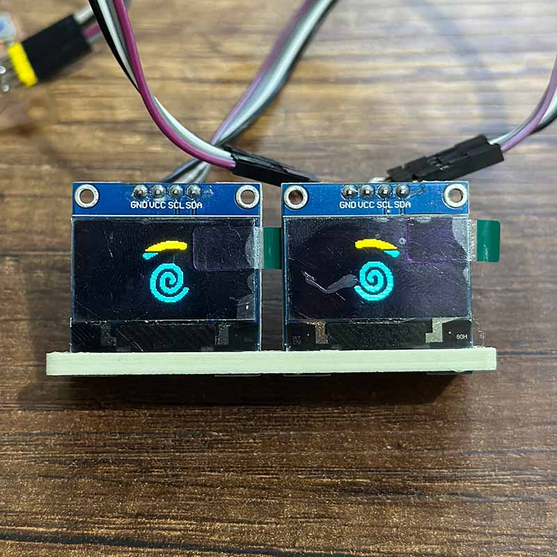
DISPLAYING MESSAGES IN SSD1306 WIHT BLUETOOTH
I also tested Bluetooth communication with the following program, a modified version from the Seeed Studio wiki. It allows connecting the Xiao ESP32C3 from a mobile phone and sending messages that are then displayed on the SSD1306 screen
#include <Wire.h>
#include <Adafruit_GFX.h>
#include <Adafruit_SSD1306.h>

#include <BLEDevice.h>
#include <BLEUtils.h>
#include <BLEServer.h>

#define SCREEN_WIDTH 128
#define SCREEN_HEIGHT 64
#define OLED_RESET -1
#define OLED_ADDR_1 0x3D

Adafruit_SSD1306 display(SCREEN_WIDTH, SCREEN_HEIGHT, &Wire, OLED_RESET);

// See the following for generating UUIDs:
// https://www.uuidgenerator.net/

#define SERVICE_UUID        "4fafc201-1fb5-459e-8fcc-c5c9c331914b"
#define CHARACTERISTIC_UUID "beb5483e-36e1-4688-b7f5-ea07361b26a8"

class MyCallbacks: public BLECharacteristicCallbacks {
		void onWrite(BLECharacteristic *pCharacteristic) {
		  std::string value = pCharacteristic->getValue();

		  	if (value.length() > 0) {
			Serial.println("*********");
			Serial.print("New value: ");
			for (int i = 0; i < value.length(); i++)
			  Serial.print(value[i]);

			Serial.println();
			Serial.println("*********");

			// Actualizar la pantalla OLED
			display.clearDisplay();
			display.setTextSize(1);
			display.setTextColor(SSD1306_WHITE);
			display.setCursor(0, 0);
			display.print("Received:");
			display.setTextSize(2);
			display.setCursor(0, 20);
			// Muestra el mensaje recibido en la pantalla
			display.print(value.c_str());
			display.display();
		  }
		}
	};

void setup() {

Wire.begin();

display.begin(SSD1306_SWITCHCAPVCC, OLED_ADDR_1);
display.clearDisplay();
display.setTextSize(1);
display.setTextColor(SSD1306_WHITE);
display.setCursor(0,0);
display.println("Setup");
display.display();

Serial.begin(115200);

BLEDevice::init("MyESP32");
BLEServer *pServer = BLEDevice::createServer();

BLEService *pService = pServer->createService(SERVICE_UUID);

BLECharacteristic *pCharacteristic = pService->createCharacteristic(
			CHARACTERISTIC_UUID,
			BLECharacteristic::PROPERTY_READ |
			BLECharacteristic::PROPERTY_WRITE
			);

pCharacteristic->setCallbacks(new MyCallbacks());

pCharacteristic->setValue("Hello World");
pService->start();

BLEAdvertising *pAdvertising = pServer->getAdvertising();
pAdvertising->start();
}

void loop() {
	delay(2000);
}
To send messages from my cell phone, I used the LightBlue application. The result is as follows:"
Download:
Here you can download de printable parts of the mechanical structure: