Group assignment:
Send a message between two projects
Document your work to the group work page and reflect on your individual page what you learned
Individual assignments
Design, build and connect wired or wireless node(s) with network or bus addresses and a local interface
Learning outcomes:
Demonstrate workflows used in network design
Implement and interpret networking protocols and/or communication protocols
Requirements for the assignment:
Linked to the group assignment page
Documented your project and what you have learned from implementing networking and/or communication protocols.
Explained the programming process(es) you used.
Outlined problems and how you fixed them.
Included design files (or linked to where they are located if you are using a board you have designed and fabricated earlier) and original source code.
Included a ‘hero shot’ of your network and/or communications setup
Learning Highlights:
Here is the complete Group Assignment
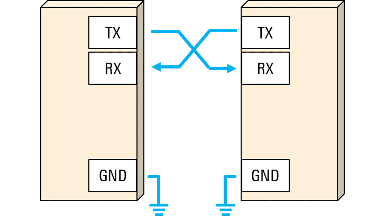
Definition: UART stands for universal asynchronous receiver/transmitter. It's a protocol for exchanging serial data between devices using only two wires plus a ground connection.
Usage: UART was one of the earliest serial protocols and is commonly found in devices like RS-232 interfaces and external modems. While its popularity has decreased with the rise of technologies like USB and Ethernet, UART is still used for low-speed applications due to its simplicity and low cost.
Asynchronous Communication: UART is asynchronous, meaning it doesn't require a shared clock signal between devices. Instead, both devices must agree on the baud rate, frame structure, and other parameters for successful communication.
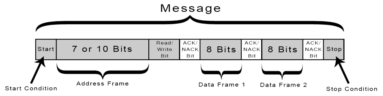
Frame Format: A UART frame consists of start and stop bits that indicate the beginning and end of user data, along with optional data bits (usually 7 or 8) and an optional parity bit for error detection.
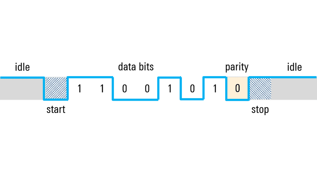
Parity Bit: The parity bit, if used, helps detect single-bit errors in the transmitted data. It can be set for even or odd parity based on the desired error-checking scheme.
Other Serial Protocols: While UART is still widely used, it has been replaced in some applications by protocols like SPI and I2C, especially for higher-speed and more complex communication needs.
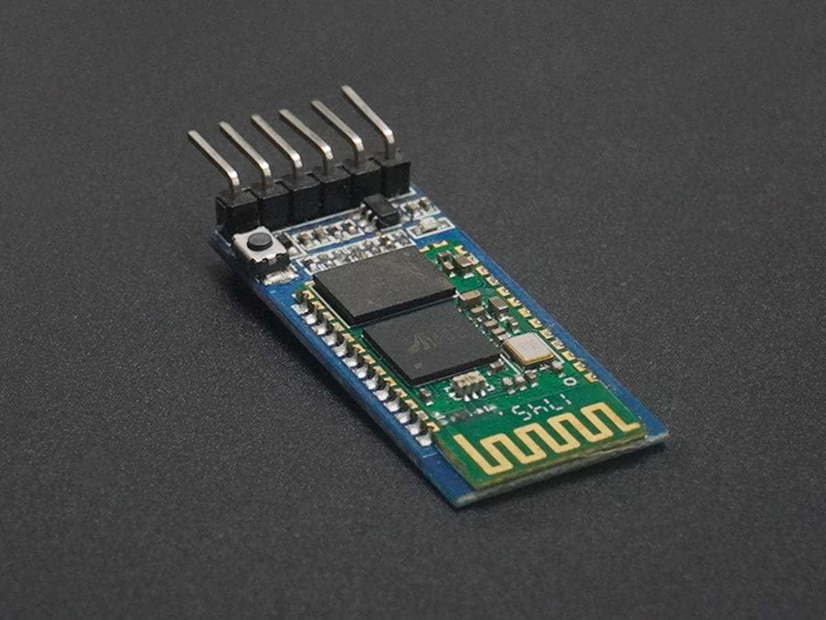
The HC-05 Bluetooth module is a versatile and widely used wireless communication module that can be integrated into various electronic projects. Here’s a comprehensive overview of the HC-05 Bluetooth module:
The HC-05 Bluetooth module is designed for wireless communication and can operate in both master and slave configurations. It operates on the Bluetooth version 2.0 + EDR (Enhanced Data Rate) and uses the 2.4 GHz ISM band for communication. The module supports several profiles, including SPP (Serial Port Profile) and HID (Human Interface Device).
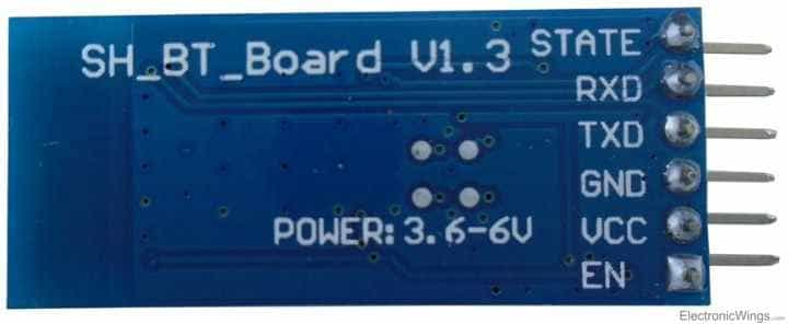
The HC-05 module typically has six pins:
You can interface the HC-05 Bluetooth module with Arduino using software serial communication. Here's a basic code snippet for receiving data from the module:
#include <SoftwareSerial.h>

    SoftwareSerial bt(2, 3); // RX, TX pins

    void setup() {
      Serial.begin(9600); // Serial monitor for debugging
      bt.begin(9600); // Bluetooth module communication
    }

    void loop() {
      if (bt.available()) {
        char receivedChar = bt.read();
        Serial.print(receivedChar); // Print received data to serial monitor
      }
    }
To configure the HC-05 module using AT commands, you need to switch it to command mode by setting the Key/EN pin high. Once in command mode, you can send AT commands through a serial terminal (e.g., Teraterm, Realterm) to change settings like the device name, baud rate, and password.
Here are some commonly used AT commands:
AT: Check communication.AT+PSWD=XXXX: Set password.AT+NAME=XXXX: Set device name.AT+UART=Baud rate, stop bit, parity bit: Change baud rate.AT+VERSION?: Get firmware version.The HC-05 Bluetooth module finds applications in:
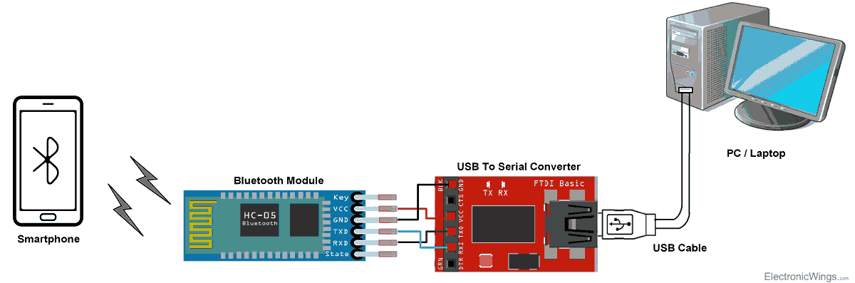
Here is the basic connection of the bluetooth module:
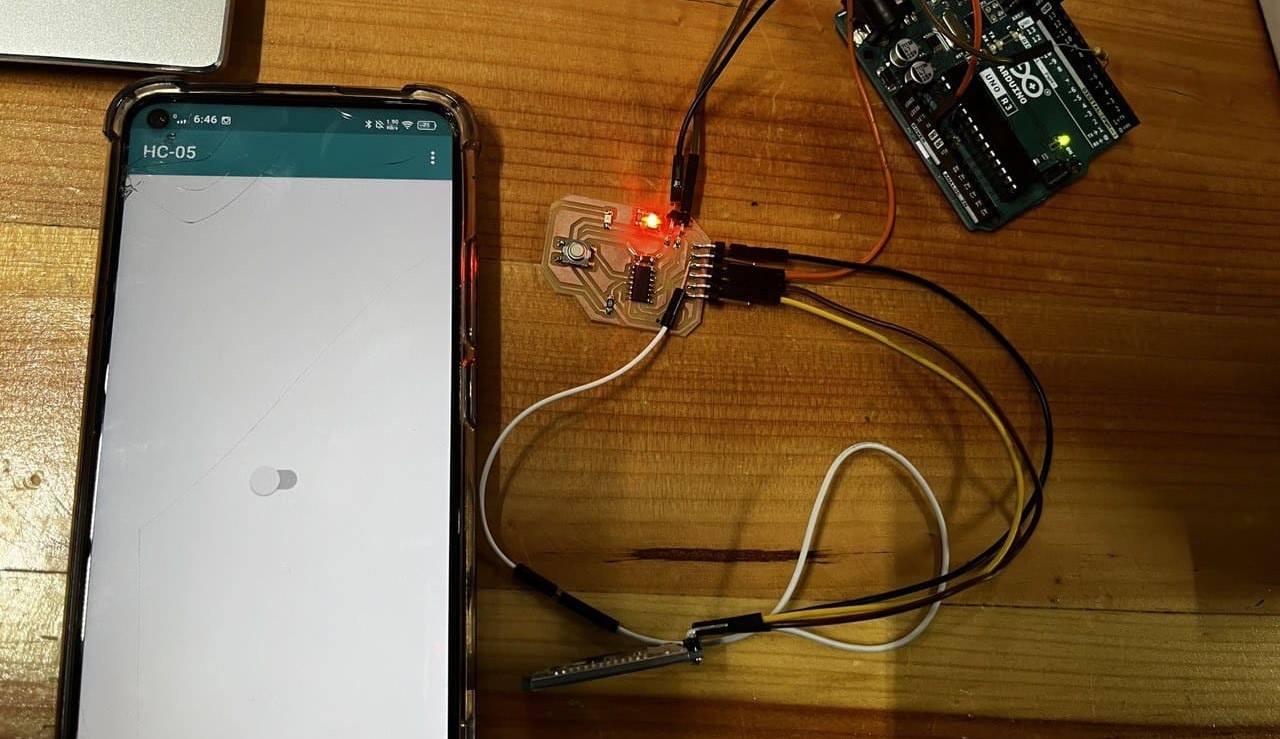
For this week, I will control an LED on my board using a smartphone to send control signals via bluetooth to the HC05 signal connected to my MCU from week 8.
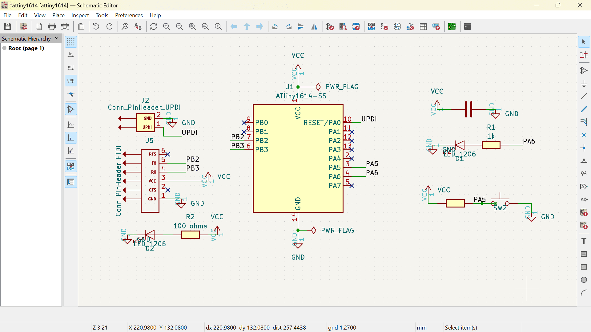
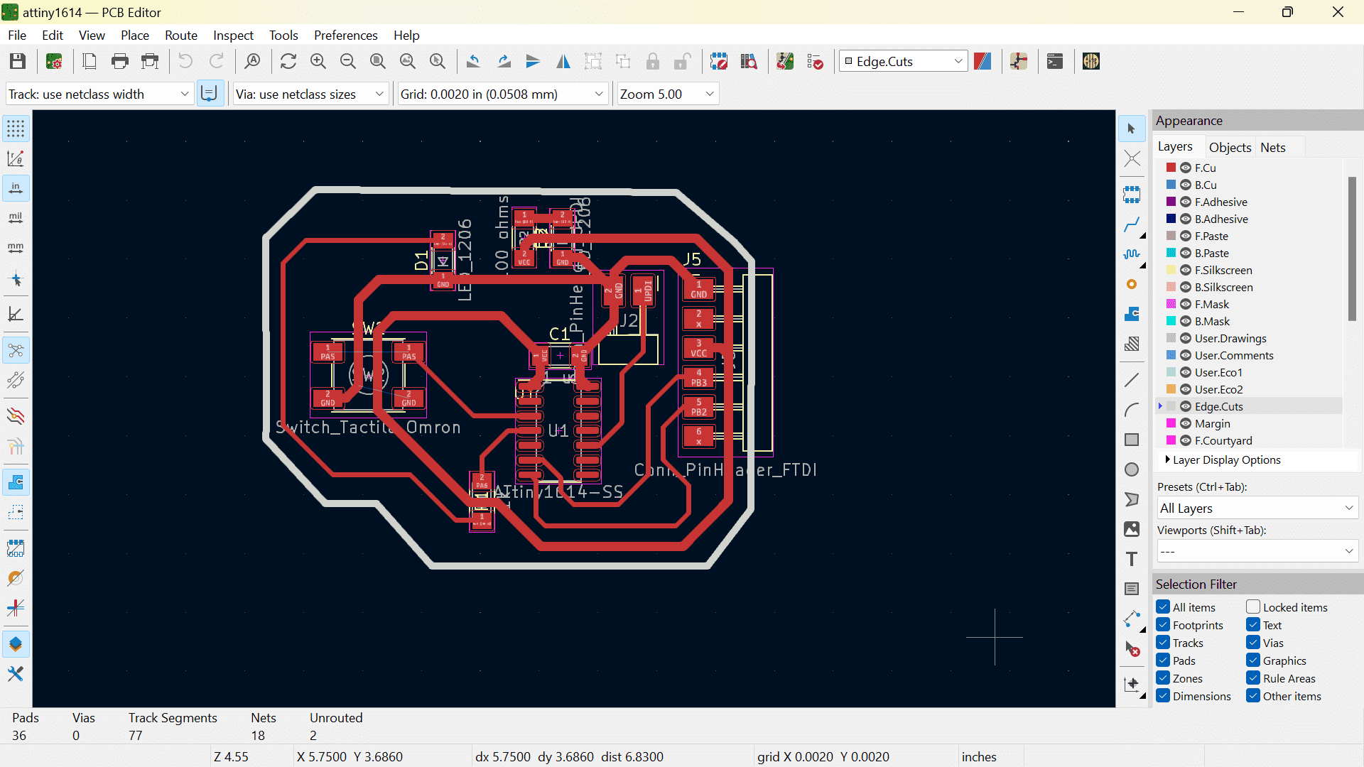
Below are the images of the schematic and PCB format of my board from week 8.
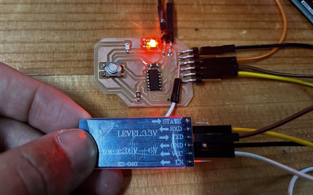
So, firstly I connected the bluetooth module to the FTDI pins on my board.
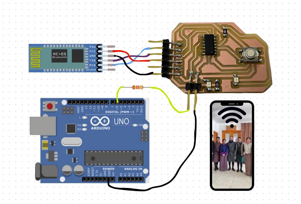
Here is a clearer diagram of the whole circuit that I made in Canva.
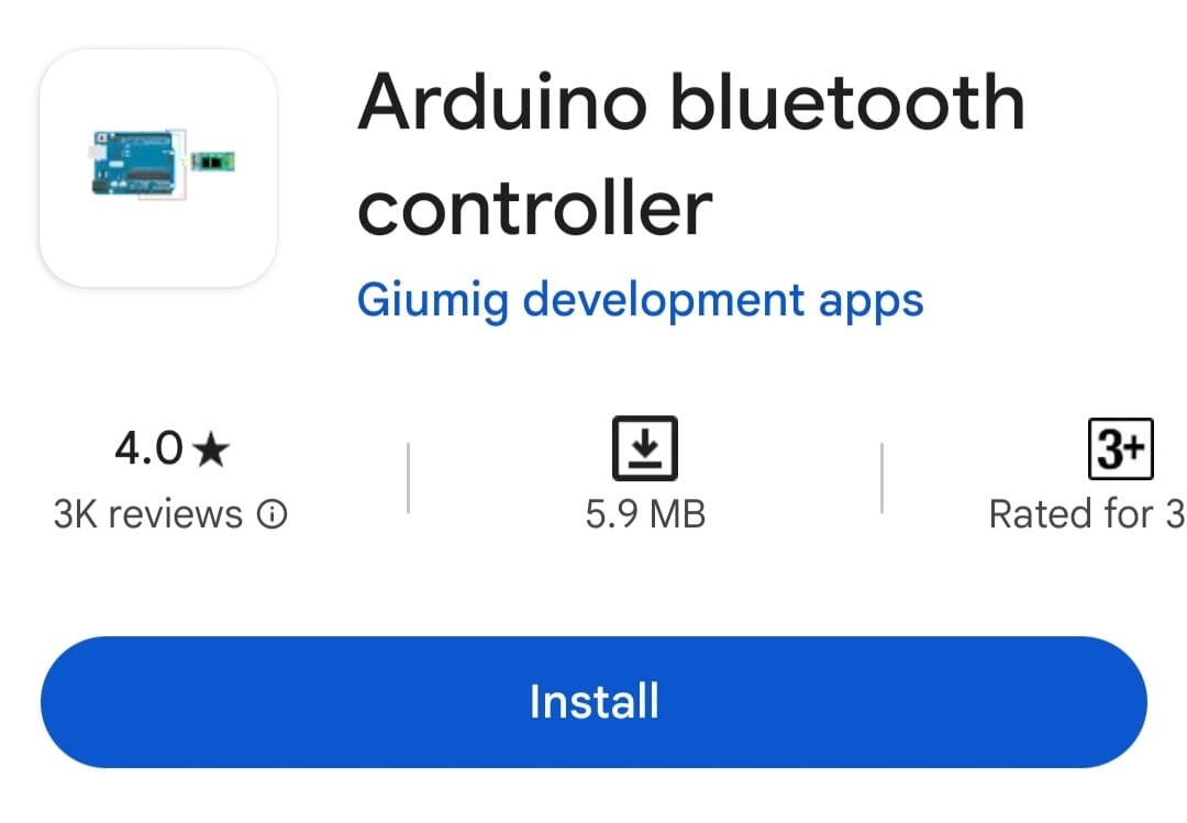
I downloaded the arduino bluetooth controller on my phone from Play Store.
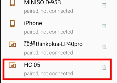
Then I connected my phone to the bluetooth module named HC-05
After connecting it to the module, 3 options show up.
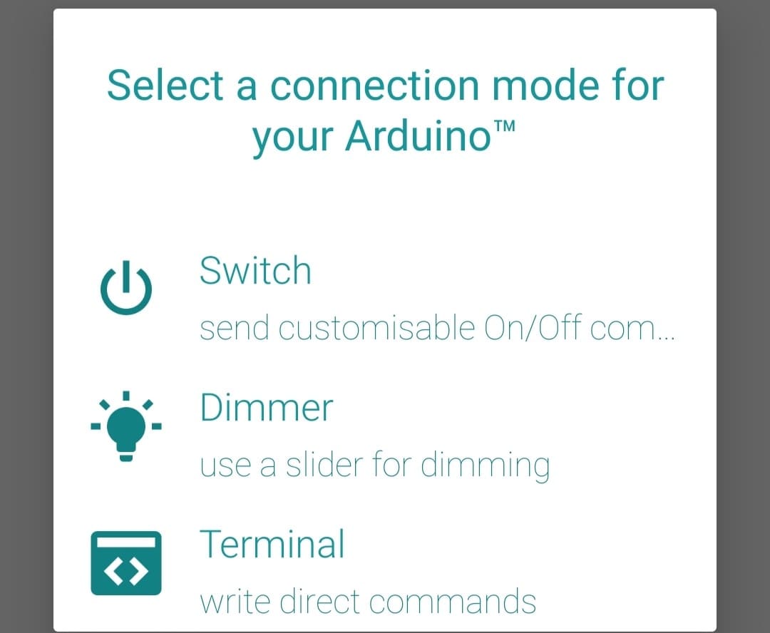
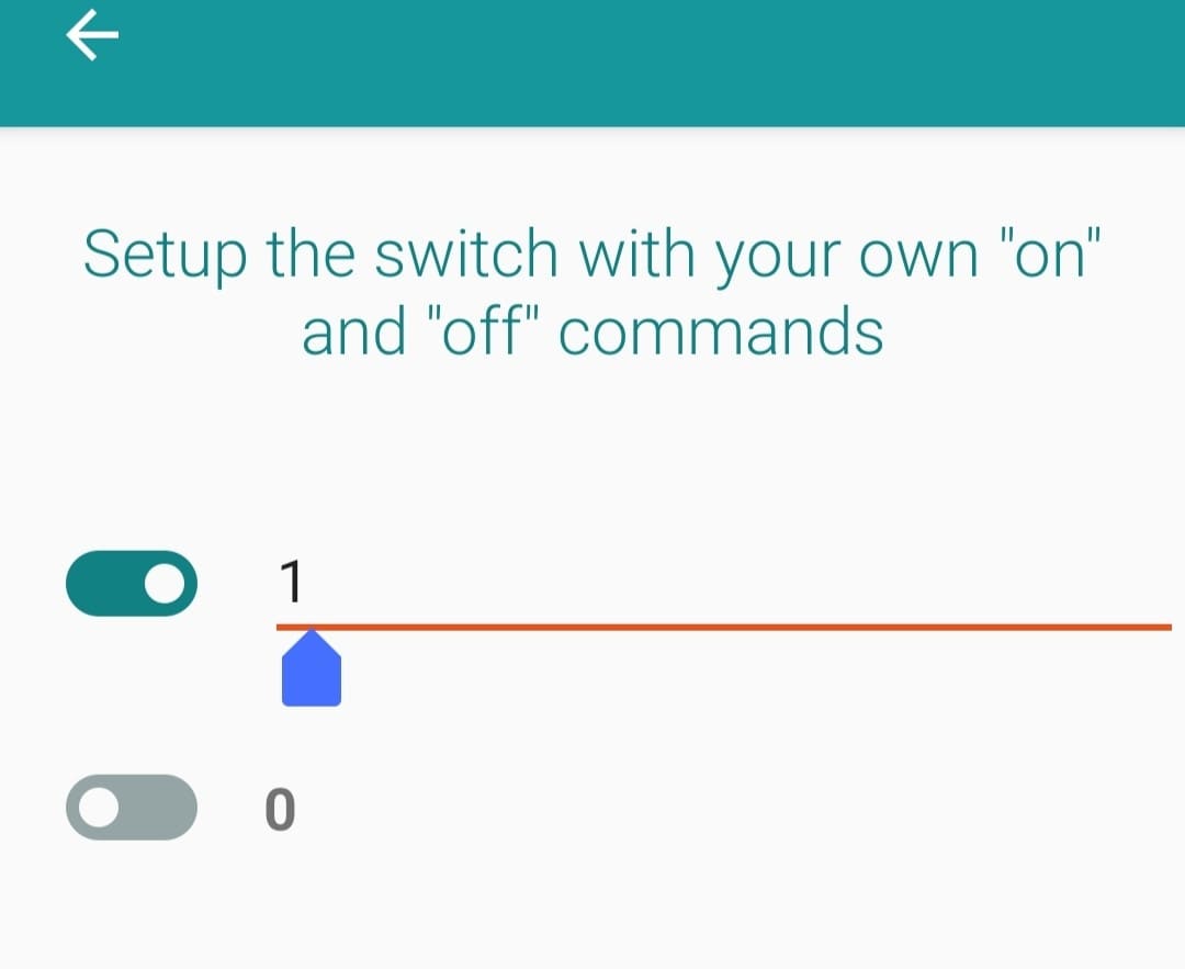
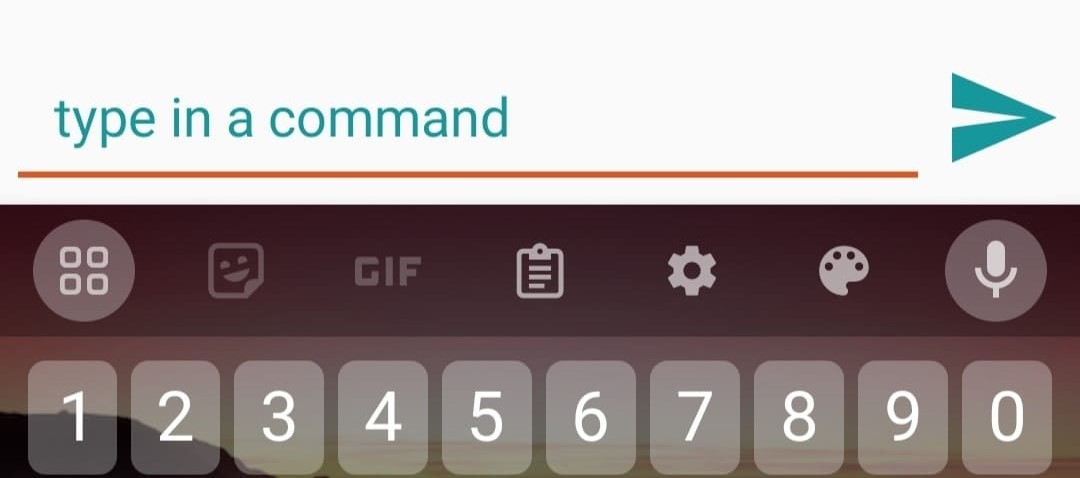
I chose the switch option and did the switch setup with commands where I kept 1 for on and 0 for off
Here is a video of controlling the LED with my phone.
While for the terminal, we write direct commands. So, when I send 1, the LED turns on and when I send 0, the LED turns off.
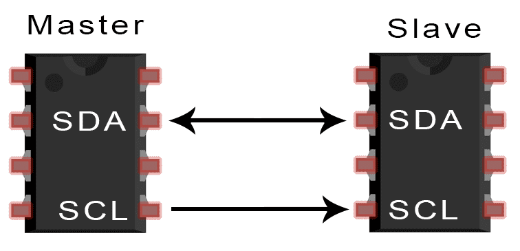
I2C is a serial communication protocol used for connecting multiple devices in an electronic system. It allows for communication between a master device and multiple slave devices using only two wires: SDA (Serial Data) and SCL (Serial Clock). I2C is commonly used in electronics projects involving components like OLED displays, sensors, and modules.
For the wired communication, I wanted to control the OLED and LCD through I2C communication.
For this, I firstly connected the OLED and LCD to the Arduino using the SDA and SCL pins.
Then used the provided code to scan the addresses of each component. This code identifies devices connected via I2C and displays their addresses in the serial monitor.
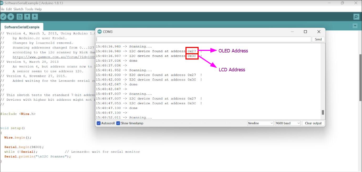
After obtaining the addresses, proceed with coding as desired. For this project, I want to display messages simultaneously on both the OLED and LCD with some delay between updates.
To achieve this, we will need to download the necessary libraries:
LiquidCrystal_I2C.h
Adafruit_GFX.h
Adafruit_SSD1306.h
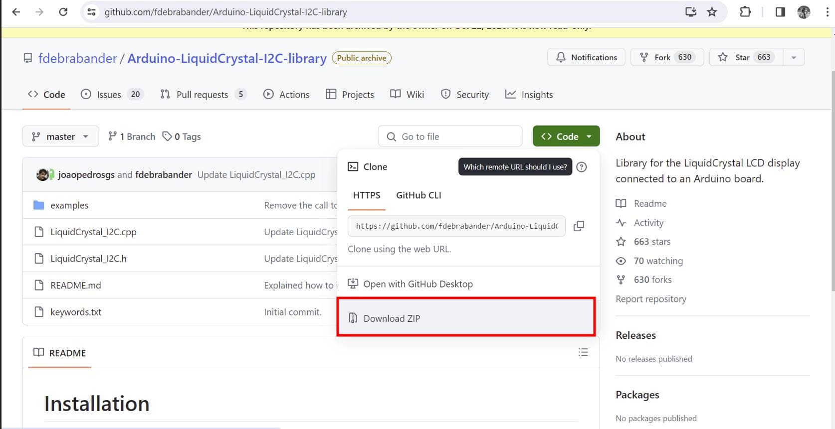
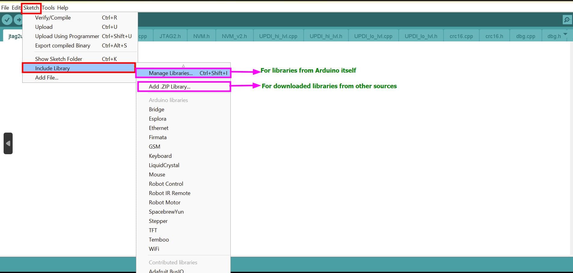
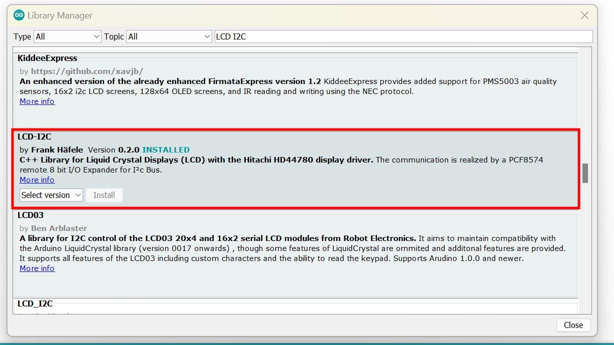
The Arduino IDE already have an inbuilt library for LCD, but without considering the I2C module. So I had to download the library for LCD I2C which you can find here or the arduino software itself.
If you are using the given library in the link, after downloading the library, it comes as a zipped folder so you can select Add .ZIP Library
I downloaded the following library for my LCD
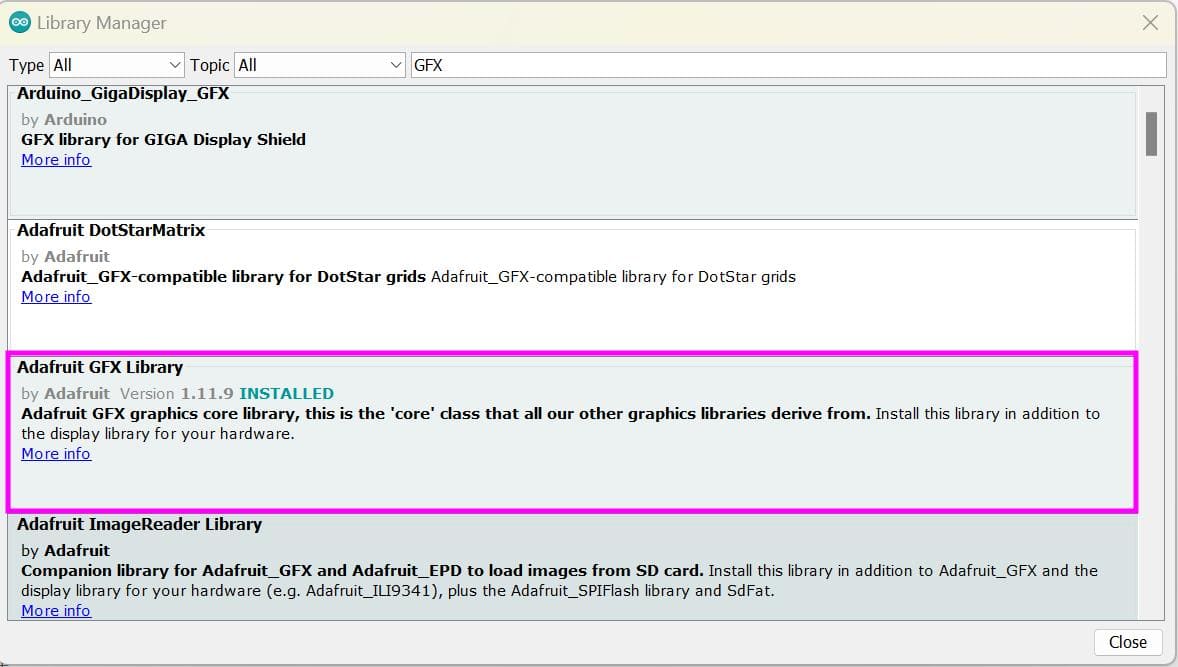
For OLED, we can find the commonly used library in the Arduino IDE software itself which can search up. Or you can find it on google. For that, the link is given here.
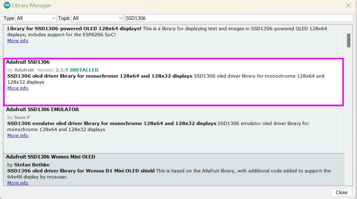
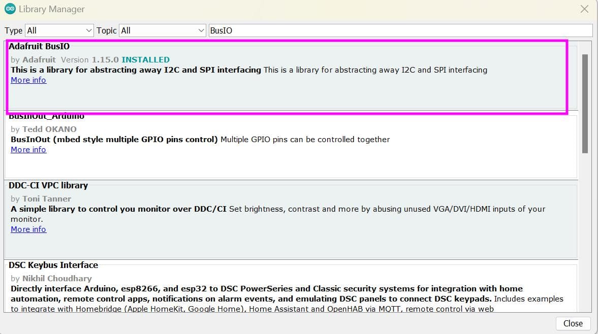
With this library, there are again two dependencies which is the Adafruit GFX Library and Adafruit BusIO
After downloading the libraries, I uploaded the following code for I2C communication.
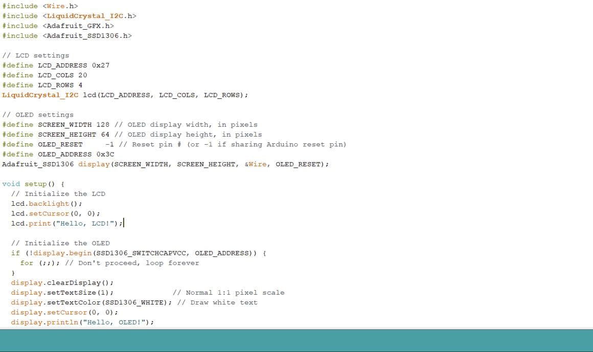
Here are the results!!