13. Networking and communications
Group assignment:
- Send a message between two projects
- Document your work to the group work page and reflect on your individual page what you learned
Individual assignment:
- design, build, and connect wired or wireless node(s) with network or bßus address
Group Assignment
We chose to do Bluetooth communication for our group assignment, and we chose the HC-05 Bluetooth module for the task.
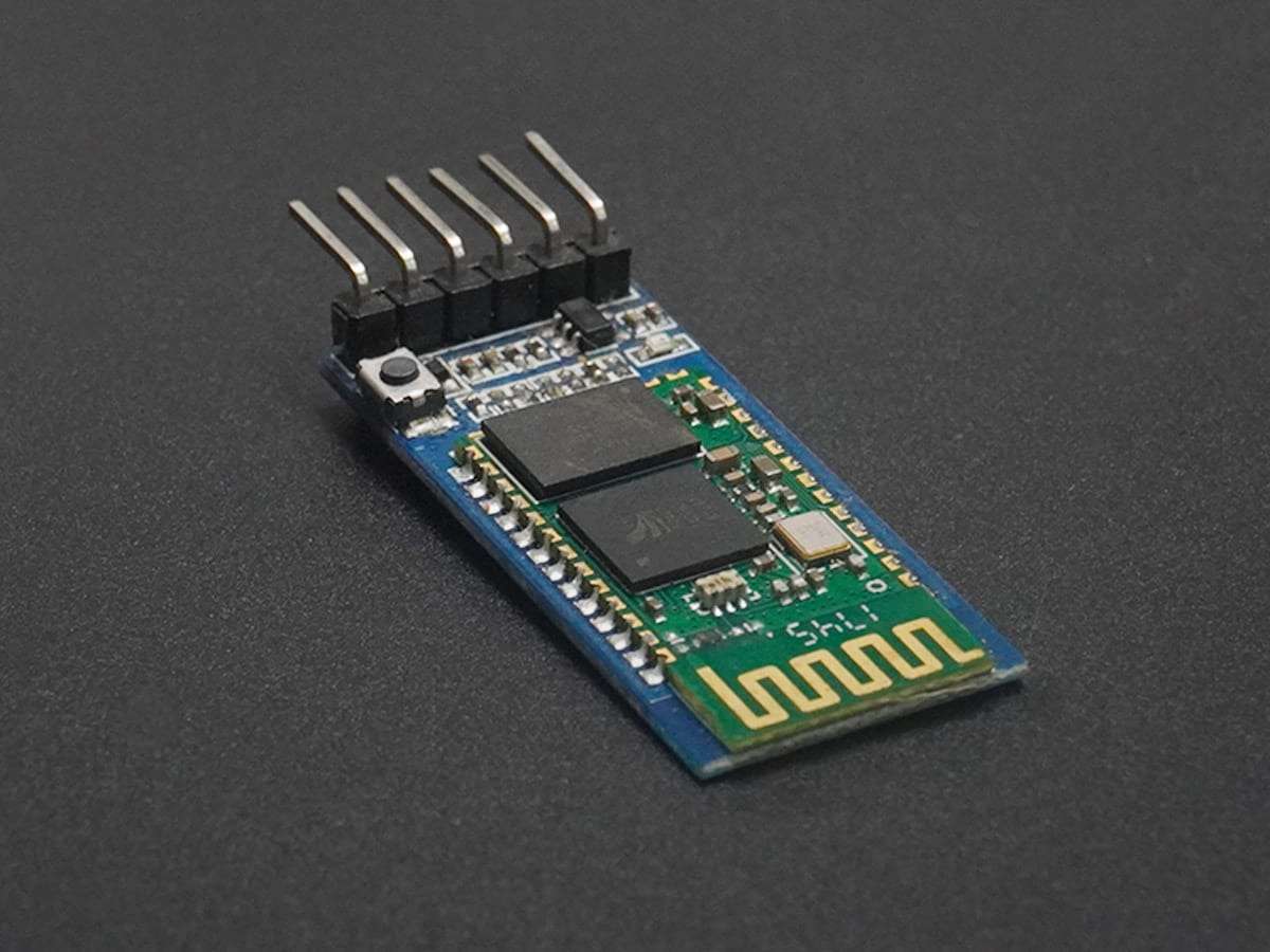
As it turns out, the HC-05 module itself has a serial interface that can be used to communicate with our Arduino boards. For simplicity, we just used Arduino Uno for the task.
Although the Arduino Uno has built-in Serial pins for doing Serial communication, that Serial port is taken
for doing communication between itself and the computer. For this, we need to use a library called
SoftwareSerial.
As its name suggests, it can take two pins on the Arduino board and make them emulate the same functionality as a Serial port, we can use it to send and receive data from the HC-05/
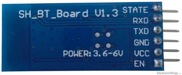
Another thing worth noting is that the data pin of the HC-05 has a logic level of 3.3v, so we need to put a voltage divider between the receiving side of the module, the Arduino can read 3.3v level as high voltage so the sending side can work without a voltage divider.
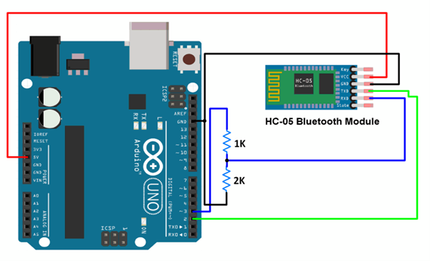
After we did the wiring correctly, we uploaded the following code to both of the Arduino boards. The program constantly reads the data sent from the computer and sends it through the Bluetooth module, as well as reads the data receiving from the module and outputs it to the computer.
#include <SoftwareSerial.h>

SoftwareSerial BTSerial(8, 9);   // RX | TX

void setup() {
  pinMode(7, OUTPUT);    /* this pin will pull the HC-05 pin 34 (KEY pin) HIGH to switch module to AT mode */
  digitalWrite(7, HIGH);

  Serial.begin(38400);
  Serial.println("Enter AT Commands:");
  BTSerial.begin(38400);  // HC-05 default speed in AT command mode
}

void loop() {
  delay(1000);
  //BTSerial.write("HIHIHI");

  //The code below allows for commands and messages to be sent from COMPUTER (serial monitor) -> HC-05
  if (Serial.available())           // Keep reading from Arduino Serial Monitor
    BTSerial.write(Serial.read());  // and send to HC-05

  //The code below allows for commands and messages to be sent from HC-05 -> COMPUTER (serial monitor)
  if (BTSerial.available())         // Keep reading from HC-05 and send to Arduino
    Serial.write(BTSerial.read());  // Serial Monitor
}
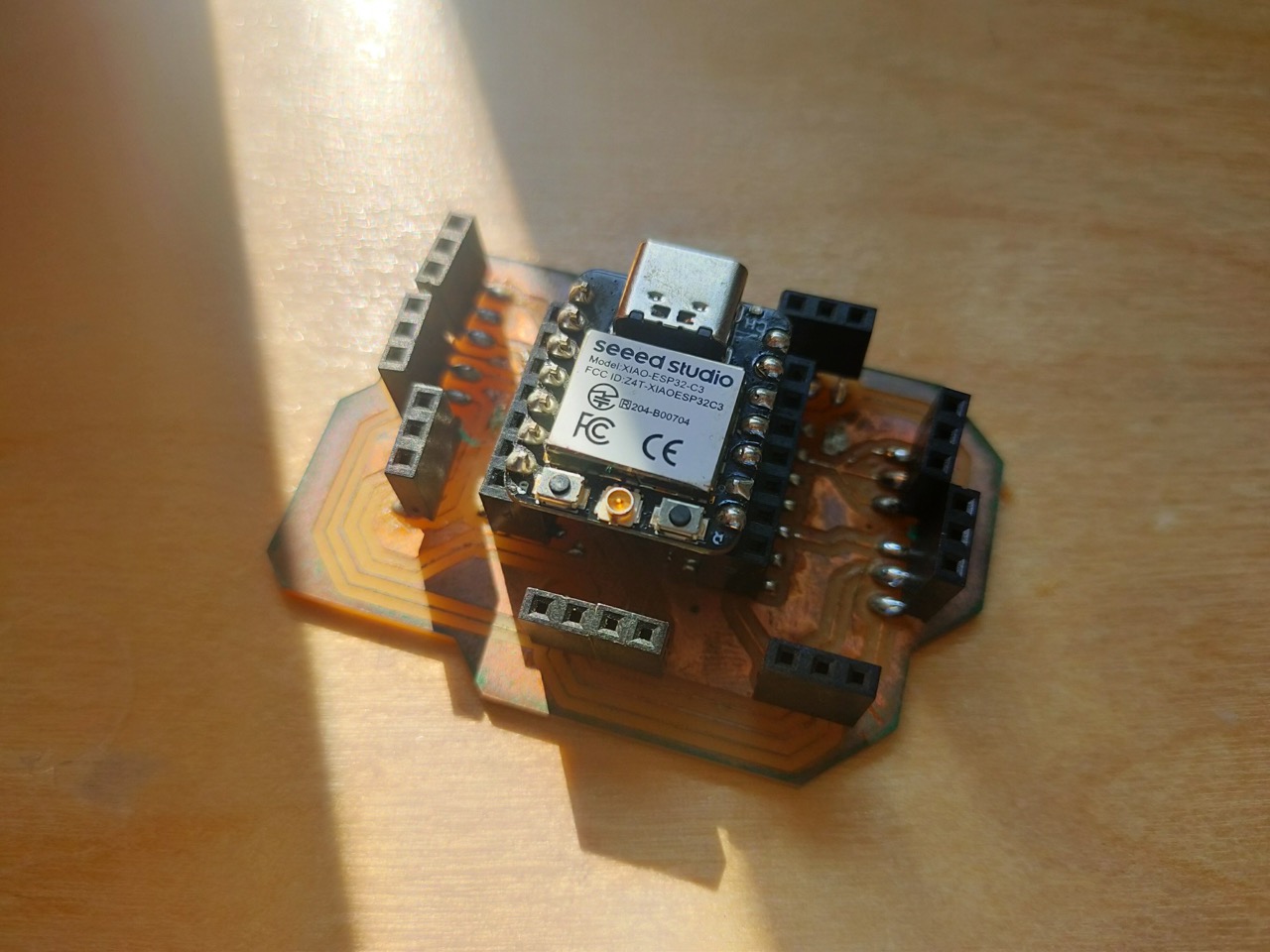
Individual Assignment
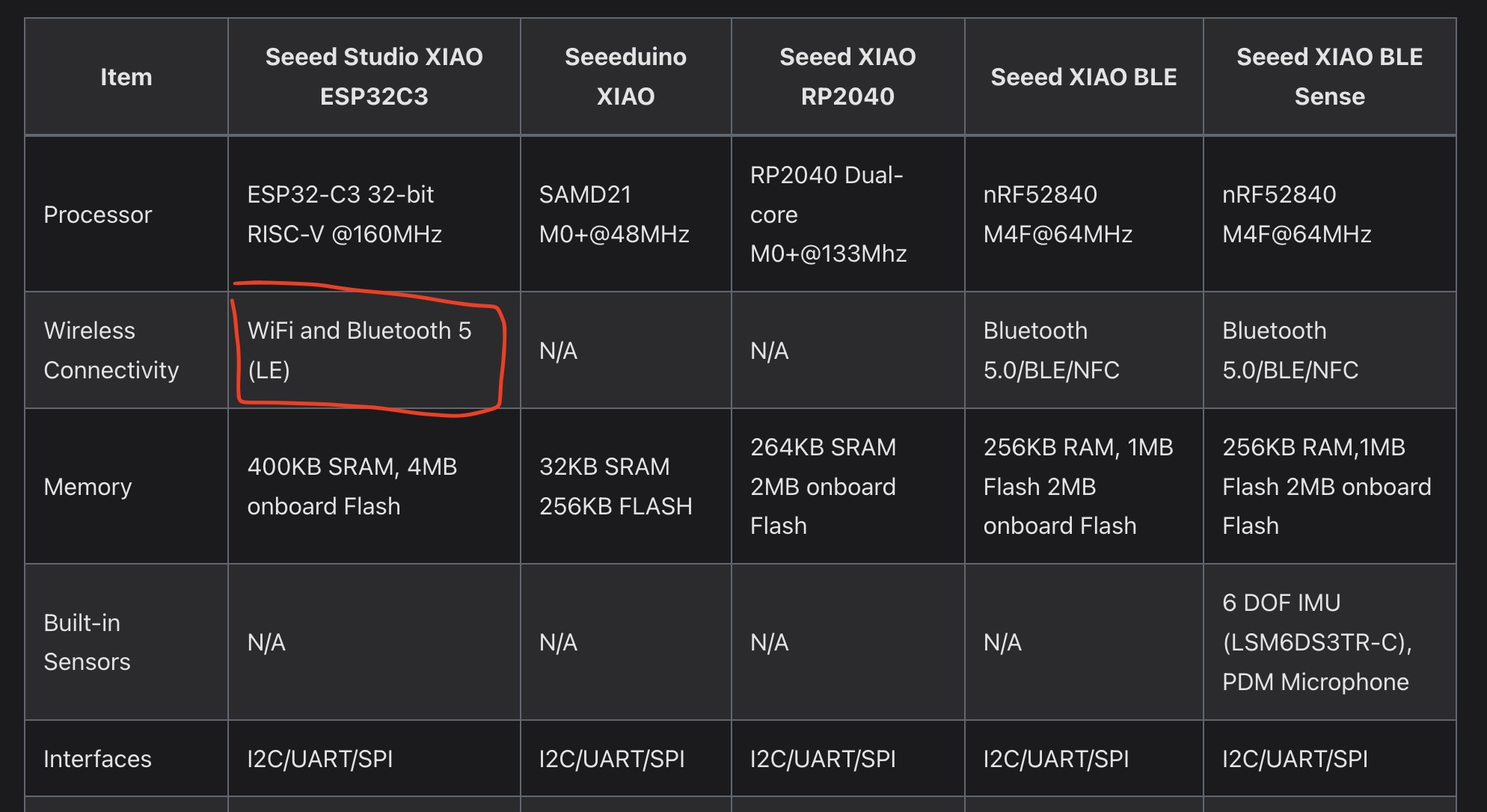
As my PCB design is a Xiao expansion board, I started researching what networking capability the Xiao board has, and I found that the XIAO ESP32C3 version has Bluetooth and WiFi capability.
Since we have a couple of these lying around in our workshop, I went on to try to experiment with them.
Installing
Because the esp32 board family is not officially included in the boards that are supported by the Arduino software, I have to install the board definition of the esp32 boards before I can program the Xiao esp32 board with Arduino IDE.
I followed the official guide from Espressif to install Esp32 boards for the Arduino software.
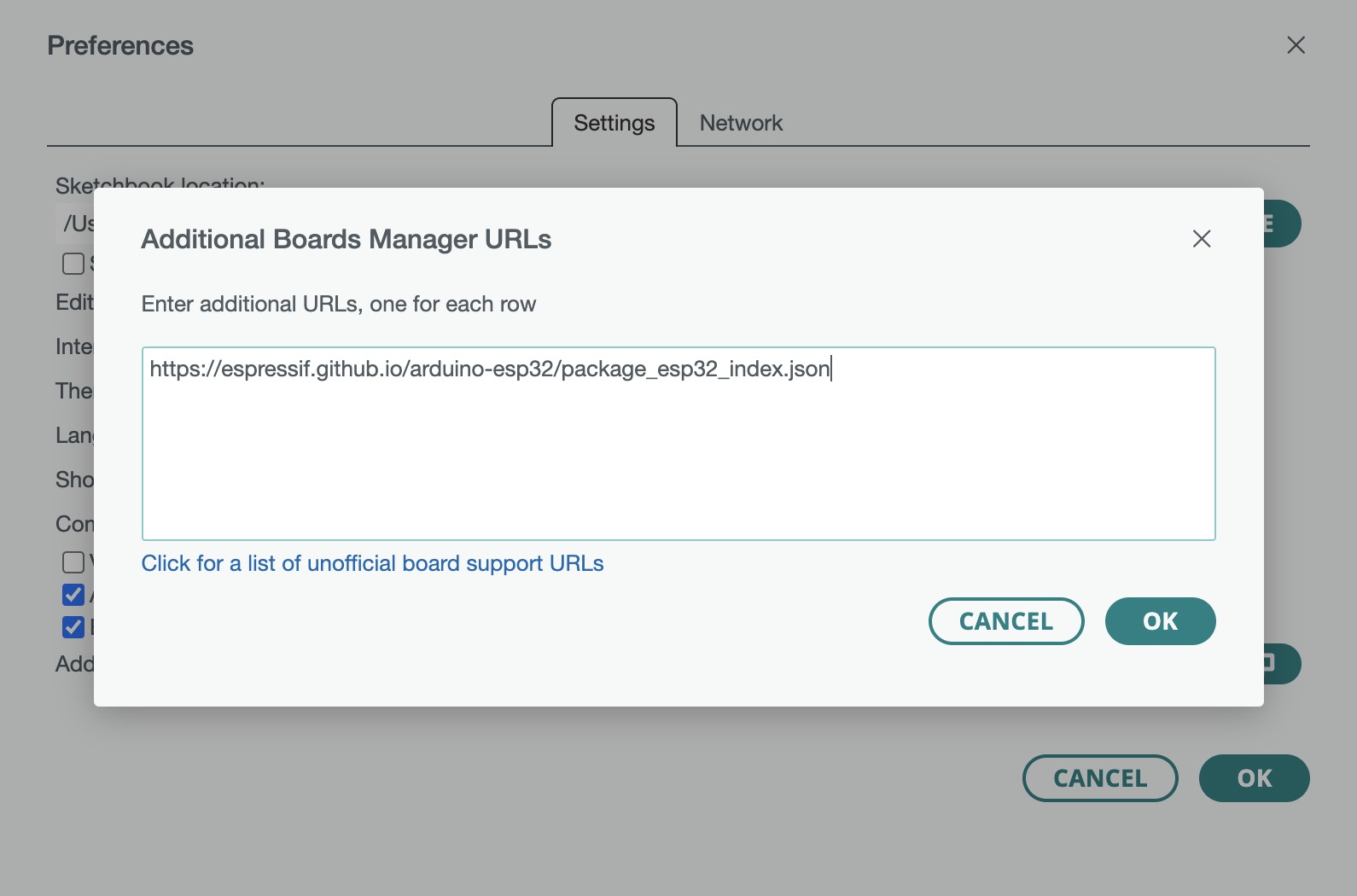
- First, open the preference memu of Arduino IDE, and paste this link into the Additional boards manager
URLs window:
https://espressif.github.io/arduino-esp32/package_esp32_index.json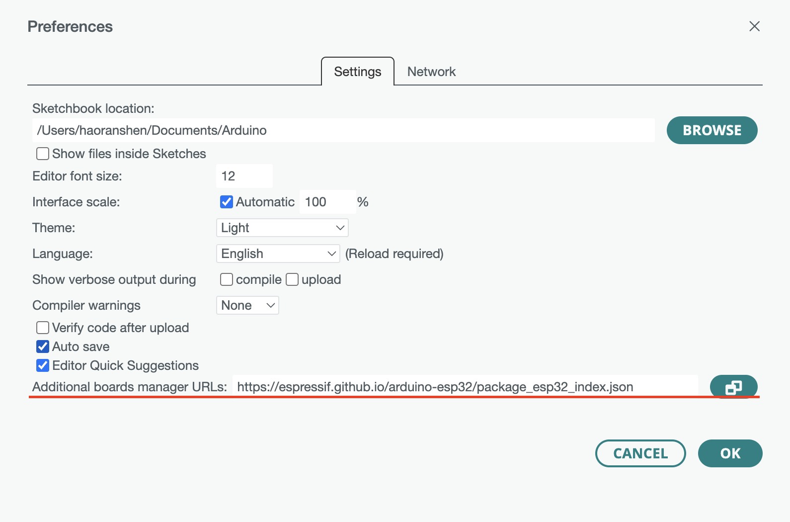
- Then open the Board manager tab and search for the
esp32platform and install.
- After installing, now I can select XIAO ESP32C3 board in Arduino IDE

- I'm on a Mac, and when I first tried to upload program to the Esp32 board, I got an error saying:
"xcrun: error: invalid active developer path (/Library/Developer/CommandLineTools), missing xcrun at: /Library/Developer/CommandLineTools/usr/bin/xcrun". After some research online, I fixed the error by opening a terminal and running the following command.
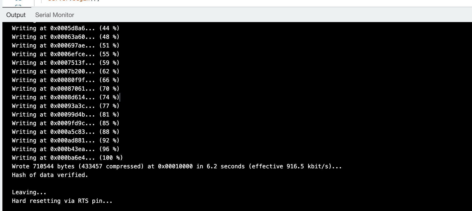
This installs the Command Line Tools package of Xcode, and after the installation is completed, I can upload the code to the board successfully.xcode-select --install
Trying WiFi
Now I can upload programs to the Xiao esp32, first I began studying some example programs that came with the esp32
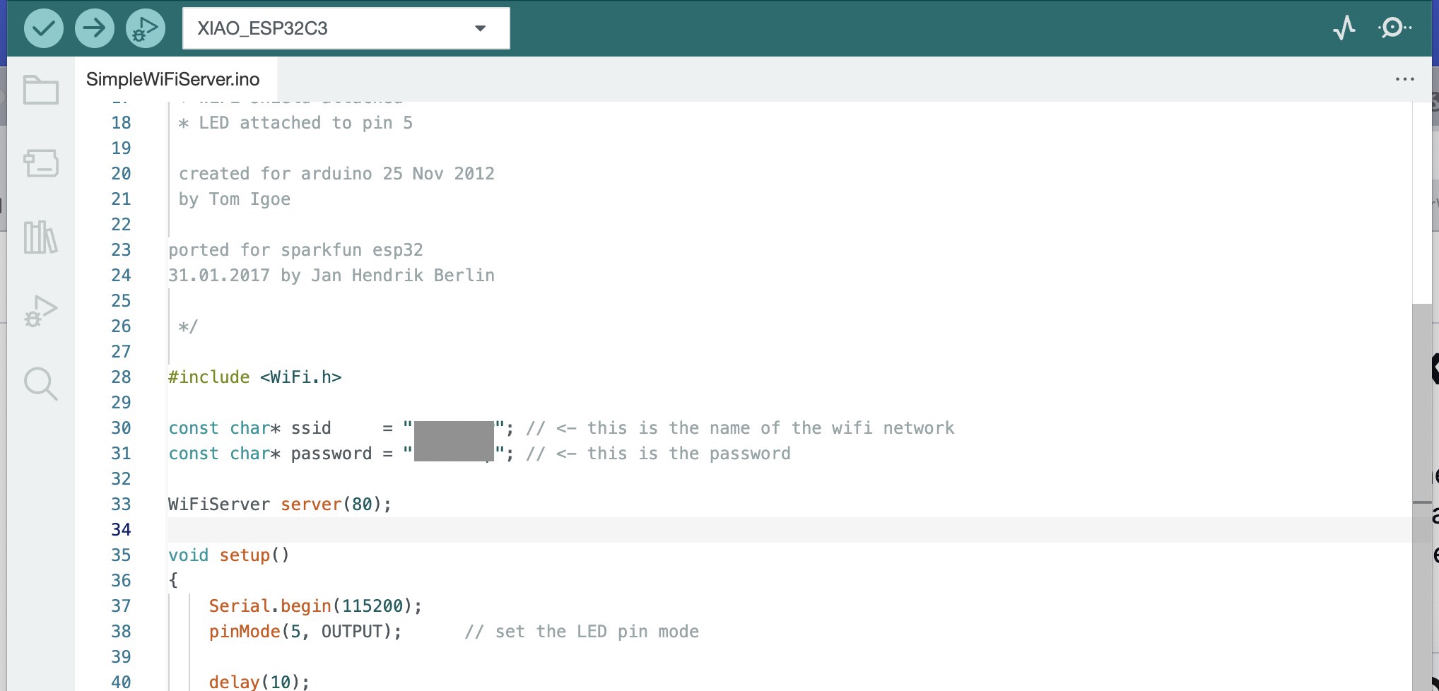
platform. As I was trying with the SimpleWiFiServer example under the WiFi category, I went into
researching how networking works between devices in general. As it turns out, this example uses the IP
protocol -
which is the shorthand for 'Internet Protocol', to let the board communicate with our computer.
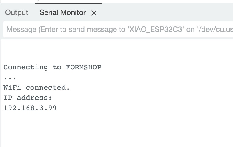
The IP protocol, as stated in its name, is the protocol used to identify different devices throughout the network, making 'the Internet' possible. In the wifi server example, the board can connect to a WiFi network by its SSID and password. After connection, the board gets an IP address from the router, printed in the serial monitor and can be used to identify the board within the network.
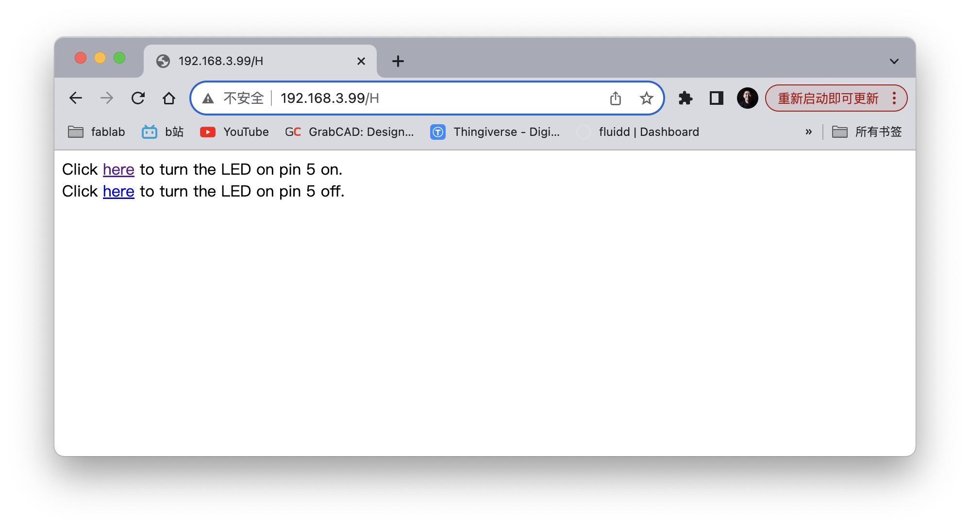
According to the comments in the example, I can now control the LED connected to the board by opening the address in the browser.
And when I connected to the board from the browser, the board printed more stuff in the serial monitor.
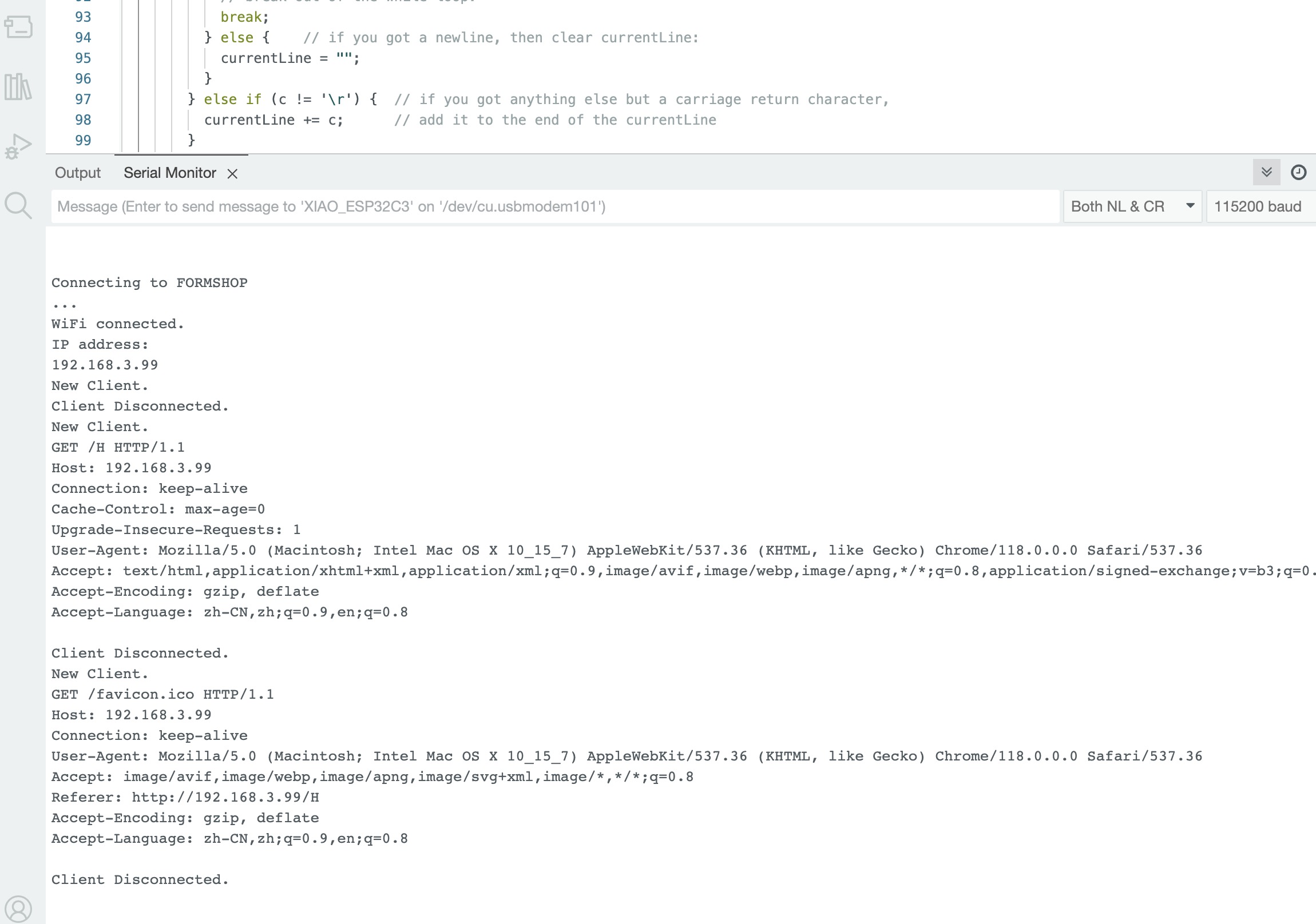
After some more research, I learned that the browser displays the web page by making requests to the servers on the Internet, and showing the web page that it got back. During the process, they uses the HTTP protocol to exchange messages. And by looking at the code, I now know that the thing printed by the board is the HTTP message it got from the browser.
Communication between boards
After studying more examples, I also found out that the ESP32 board can become a wifi hotspot itself, just like our smartphones. So now I can have other boards connect to it and send messages over the wifi.
I came up with these programs by modifying the examples, one for the receiving board that changes the LED when receiving different messages and the other for connecting to the receiving board and sending messages over a certain period.
/* WiFi receiver
   Code for receiving message over wifi
   adaped from the WiFiAccessPoint example
*/

#include <WiFi.h>

int led = 5;                    // led on pin 5
const char* ssid = "receiver";  // wifi access point name

WiFiServer server(80);  // server for receving messages
WiFiClient client;      // the client that has connected
String message = "";    // message received from the client

void setup() {
  pinMode(led, OUTPUT);

  Serial.begin(115200);
  Serial.println();
  Serial.println("Configuring access point...");

  // start an access point that has no password
  if (!WiFi.softAP(ssid)) {
    log_e("Soft AP creation failed.");
    while (1)
      ;
  }
  IPAddress myIP = WiFi.softAPIP();
  Serial.print("AP IP address: ");
  Serial.println(myIP);

  server.begin();
  Serial.println("Server started");
}

void loop() {
  WiFiClient c = server.available();  // listen for incoming clients
  if (c) {
    Serial.println("New Client.");
    client = c;  // save the connected client
  }

  if (client.connected()) {
    while (client.available()) {
      char c = client.read();
      Serial.write(c);  // print what the client has send
      if (c == '\n') {
        // message ended
        if (message == "open") {
          // if we got a message says "open", turn on the led
          digitalWrite(led, HIGH);
          Serial.println("command open: LED ON");
        } else if (message == "close") {
          // if we got a message says "close". turn off the led
          digitalWrite(led, LOW);
          Serial.println("command close: LED OFF");
        } else {
          // print the unknown command
          Serial.print("Unknown command: ");
          Serial.println(message);
        }

        message = "";  // clear the message
      } else if (c != '\r') {
        // add the character to the message
        message += c;
      }
    }
  }
}
/* WiFi sender
   Code for sending message over wifi
   adaped from the WiFiClient example
*/

#include <WiFi.h>

const char* ssid = "receiver";          // the name of the access point
const char* http_host = "192.168.4.1";  // the ip address of the wifi access point defaults to 192.168.4.1
const int http_port = 80;               // the port of the receiving server
WiFiClient client;                      // the client to send the message

bool is_on = false;  // the LED is on or not

void setup() {
  Serial.begin(115200);
  Serial.println();
  Serial.println("******************************************************");
  Serial.print("Connecting to ");
  Serial.println(ssid);

  // connect to the receiving board
  WiFi.begin(ssid);
  while (WiFi.status() != WL_CONNECTED) {
    delay(500);
    Serial.print(".");
  }
  Serial.println("");
  Serial.println("WiFi connected");
  Serial.println("IP address: ");
  Serial.println(WiFi.localIP());
}

void loop() {
  if (!client.connected()) {
    // try to connect to the receving board
    if (!client.connect(http_host, http_port)) {
      Serial.println("Failed to connect");
      delay(2000);
      return;
    }
  }

  if (is_on) {
    // send close command if the led is on
    client.print("close\n");
    client.flush();
    is_on = false;
    Serial.println("sent command: close");
    delay(3000);
  } else {
    // send open command if the led is off
    client.print("open\n");
    client.flush();
    is_on = true;
    Serial.println("sent command: open");
    delay(3000);
  }
}
As shown in the video and the code, I have one board open a wifi access point and a LED connected, another board connects to the first board and send different commands over a period of 3 seconds. When the first board receives an 'open' command, it turns on the LED, and when receiving a 'close' command, it turns off the LED.