Individual Assignment:
"Show how the design and operations of your Final Project are cleanly integrated together."
____________
Updating Model Design Elements
References for ‘Little Buddy’ 3D Model Design:
This Playlist from channel “Daniel Kreuter” was used as a reference for building ‘Little Buddy’ from scratch. [#01] Blender 3.0 Character Modeling Tutorial - Beginner Friendly [2022]I used these videos from channel “Not Very Good Guy” as references for hollowing out 3D Prints and adding Joint Keys.Blender. How to cut and key a model for 3d printing
How to cut up and key a hollow model in Blender for 3d printing
How to hollow a model in Blender for 3d printing
__________
UX Design
Genuine User Experience is still needed as the final project is not yet operational, however people I’ve shown the printed prototype had a positive reactive to its cute design so at least I know that is going in the right direction. It also has a pretty good weight distribution after performing some collision tests. Will continue to test and review with users as the final project evolves.Packaging
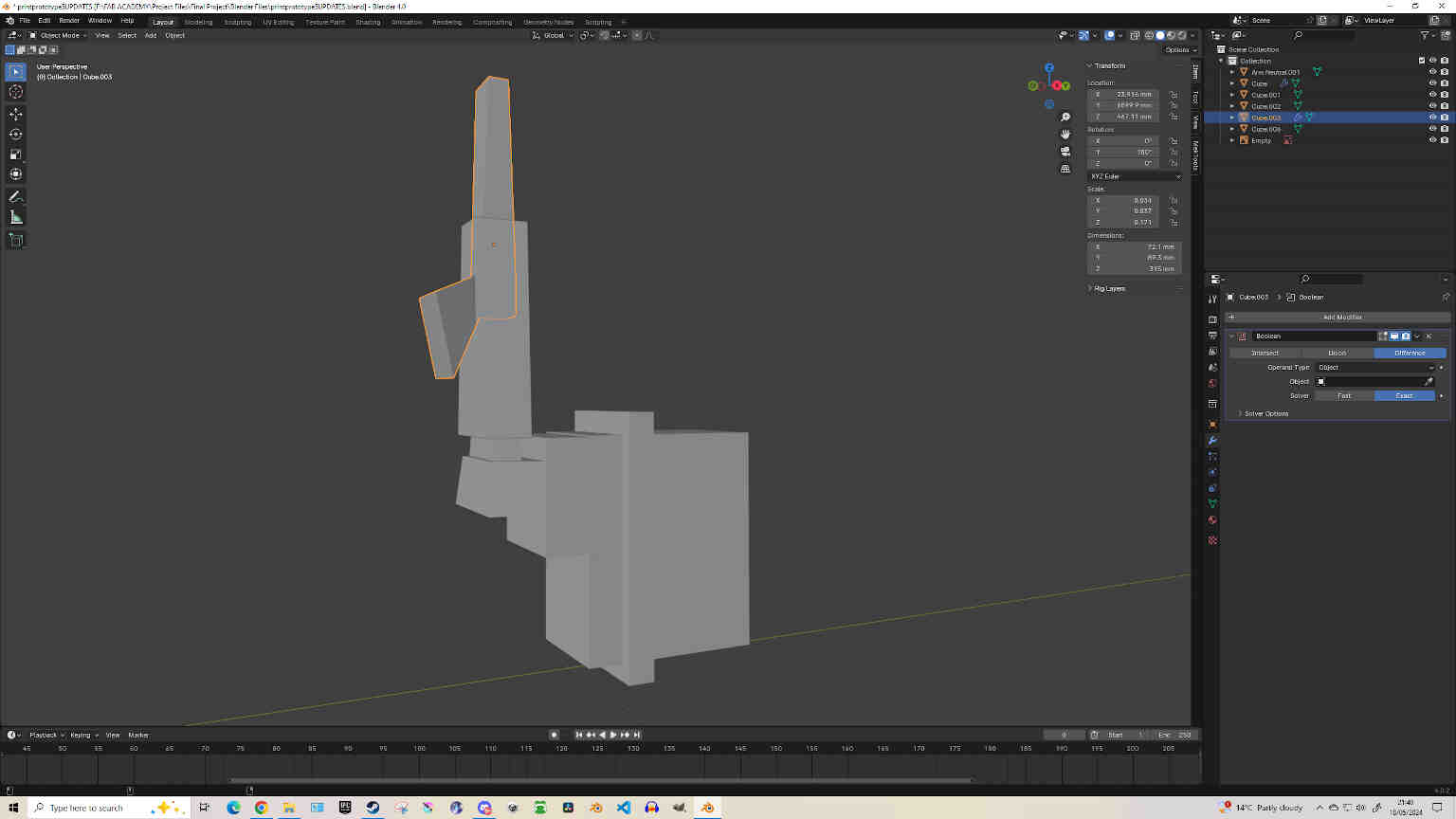
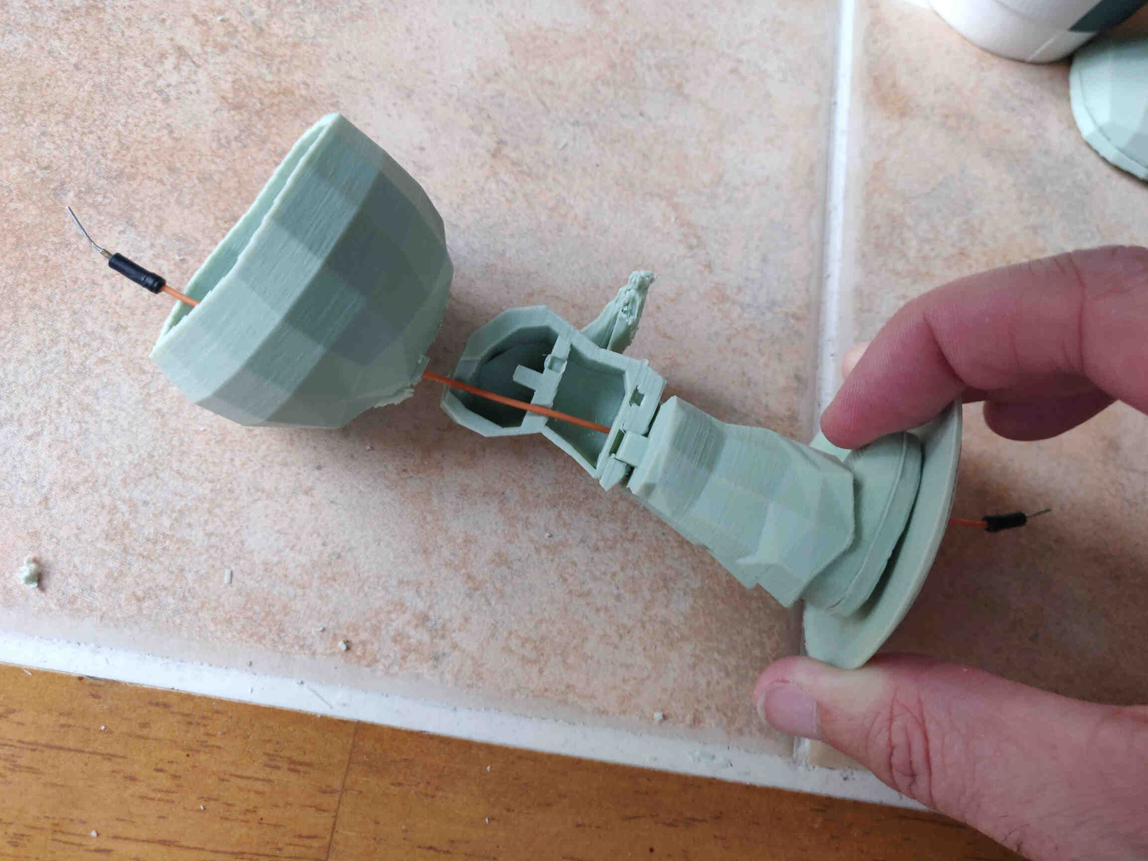
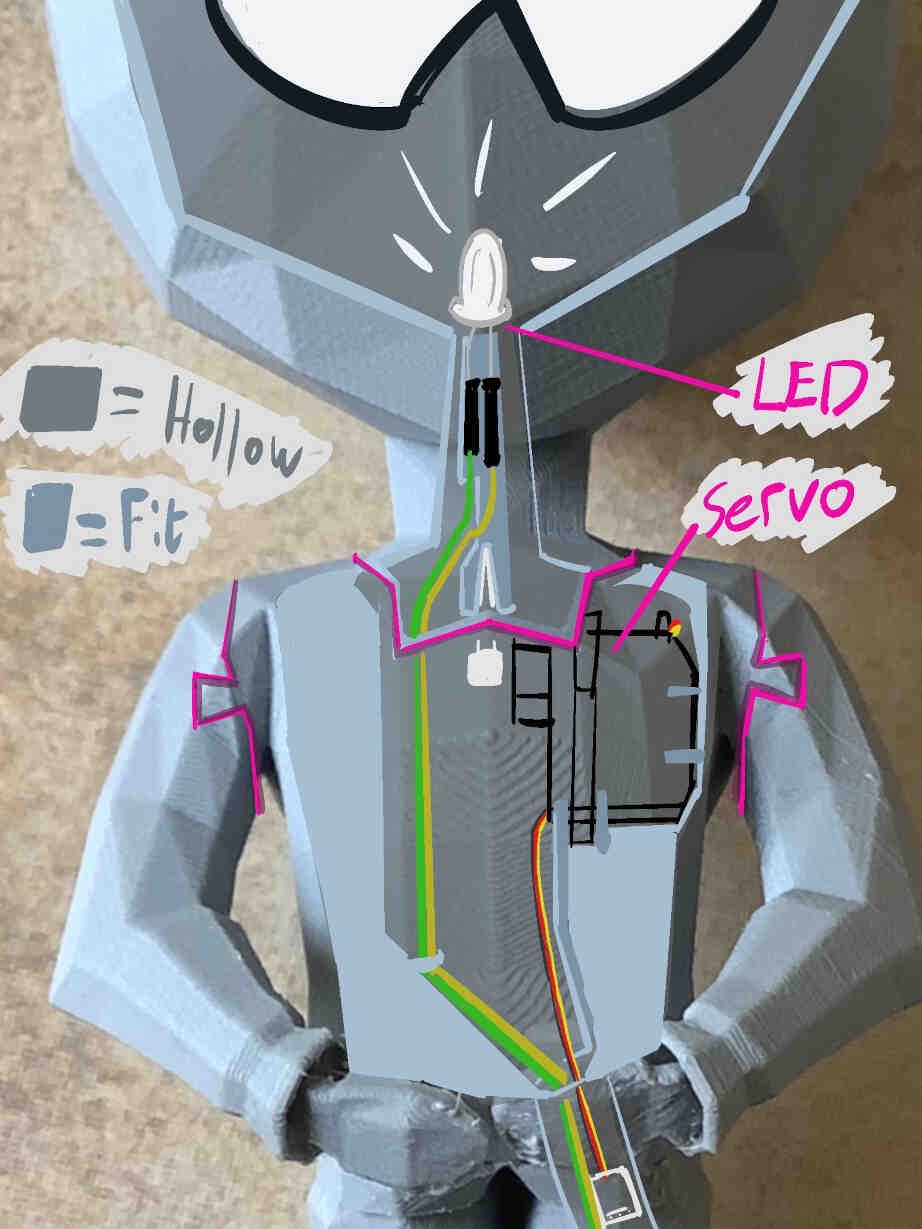
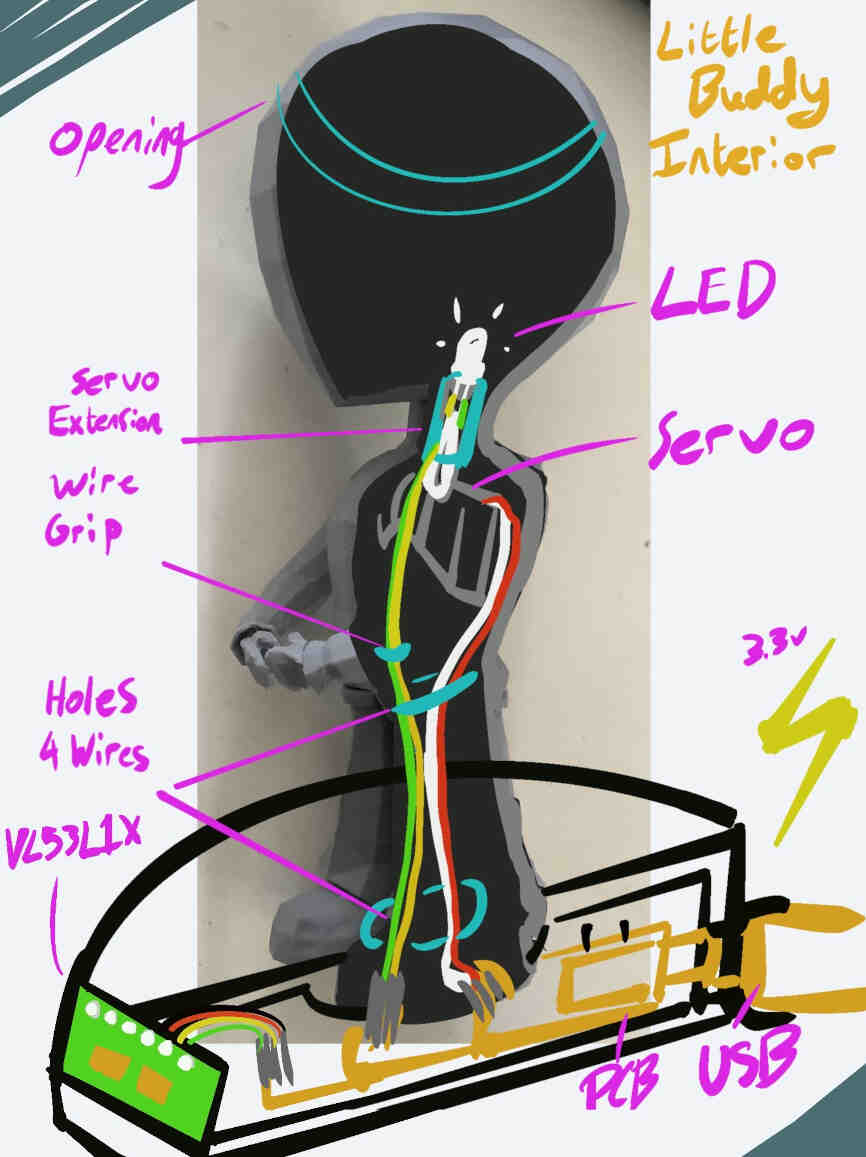
I’ve designed the Base of the product to house the PCB - which will have a semi-circle shape fitted around the back of the base, with a wired extension for the Time of Flight sensor to reach the front of the base, allowing interaction with the users. Using a boolean modifier, I added a tunnel that will go through the right side of the model (his left leg) and through the chest up to the neck. I’ve added a neck extension that will give greater reach for the servo to stably connect to the head. This extension also has an extra slot on the tip to hold the LED and allow for connections to be safely made. However this design implementation may not work out but it’s worth testing and improving. The model is separated into parts so that it can be assembled & disassembled by anyone. This makes it easier for me to make improvements on the design and integration while also allowing users room for customisation. I have ideas for an actual packaged design but I need to focus my attention on the product itself first.Testing
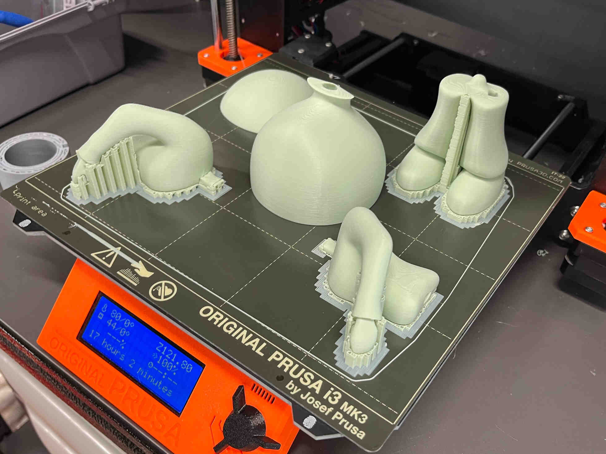
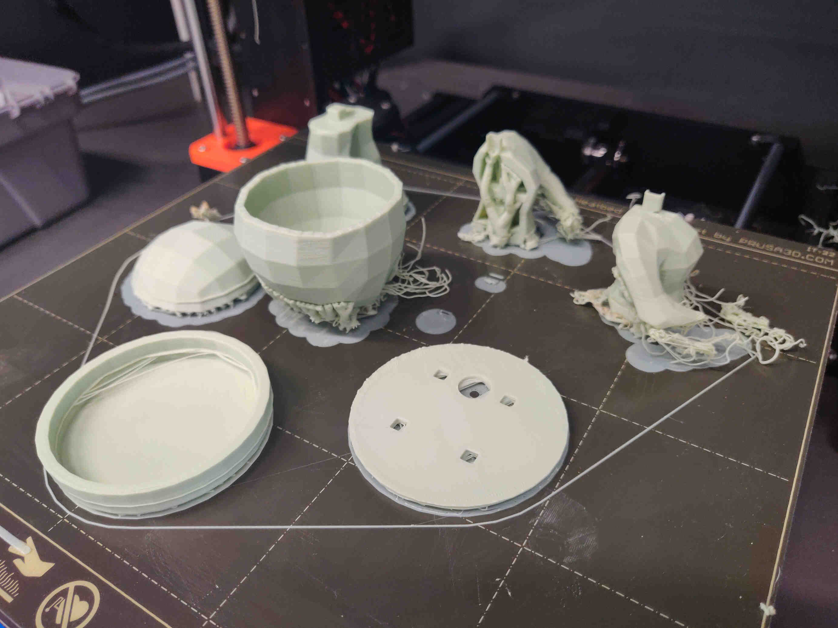
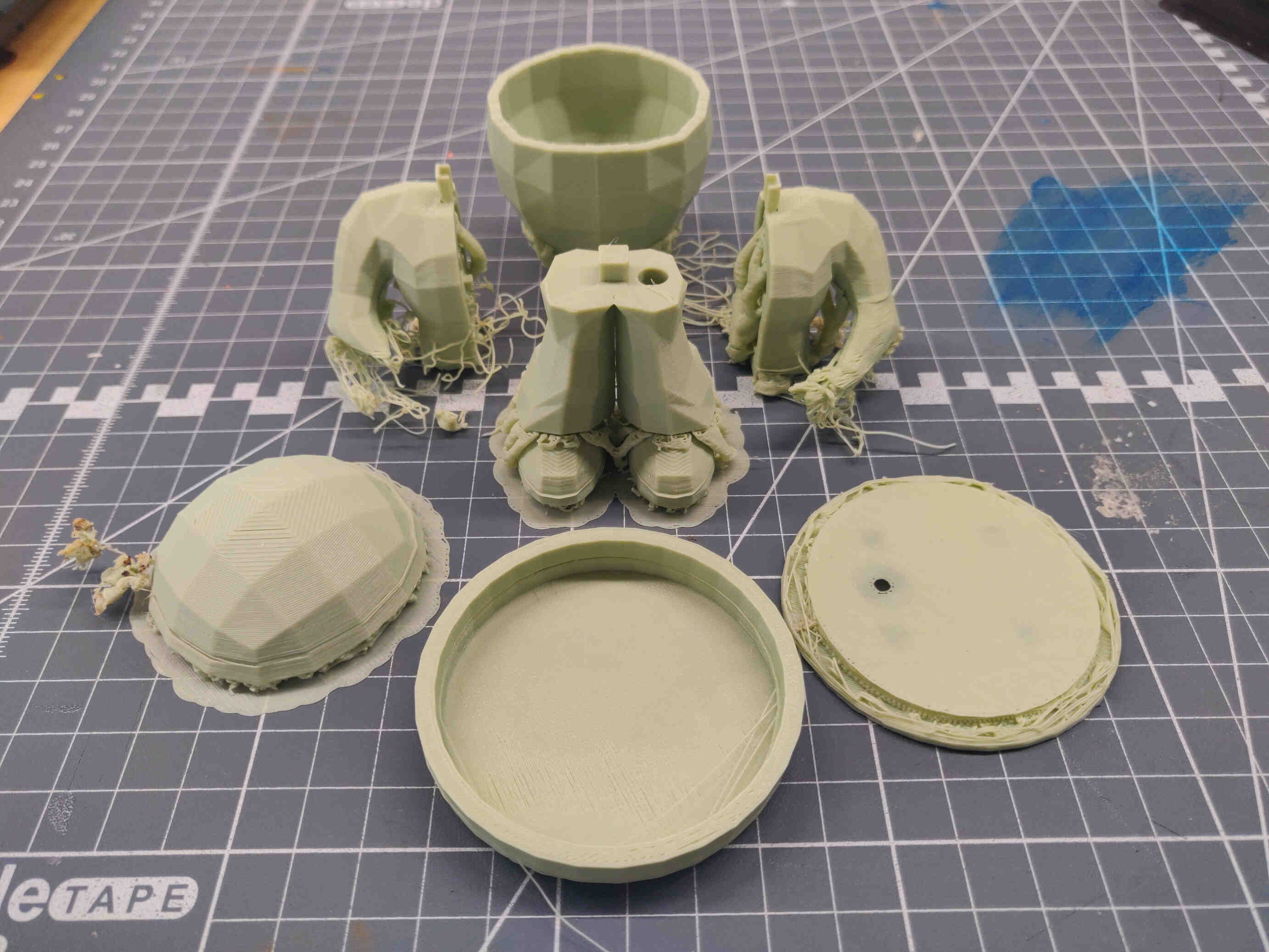
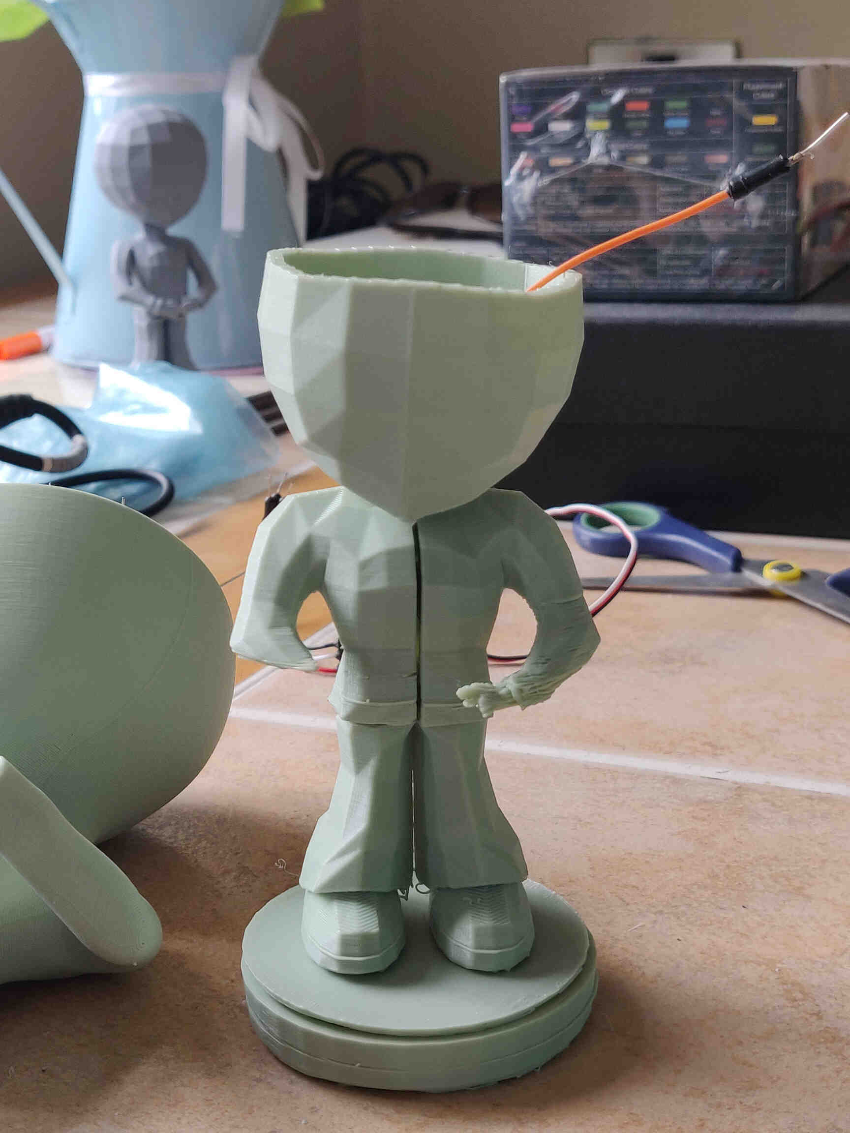
3D Print: I printed 2 versions of my updated model design - one version with seperated parts, wiring routes and hollowed out, including a Base and servo extension. The other was a rushed High Poly model that quickly subdivided. This was to get a feel of the model's current state, the height measurements, fitting, print quality, etc. Both were printed on a Prusa 3D Printer with a 0.20 nozzle and printed at 0.20 Detail. This was an issue for smaller prints trying to form small parts, but the quality was still there, but 0.20 Detail is too thick for smaller designs and keying.PCB: I was running out of time time to physically test my PCB design as it would take another day or so to fabricate, but I have tests the Arduino / Breadboard connection and uploaded the code through Arduino IDE and this was the result:
TEST AND EXPLAIN RESULT!!!
Failure modes:
The first version of my new design finished printing at 3pm Tuesday after a couple printing issues. Printing issues were due to unnecessary supports being knocked over, interrupting the print layers and bed heating being too low for the new PLA material being used. (fixed by re-slicing, orienting objects appropriately, manually placing supports and raising the bed heating by 10 degrees via the Prusa Printer interface).__________
Tasks to complete Over Weekend (May 18th-19th):
- Document New Plans for updating design. (DONE)
- Illustrate the internal design and wiring in Procreate. (DONE)
- 3D Design a Servo Motor using correct measurements for references. (DONE)
- Adjust 3D Model Topology and sizes in Blender. (DONE)
- Hollow out Model and Adjust Internals for Circuitry. (DONE)
- Separate Head+Neck / Arms / Legs models. (DONE)
- Research and Concept a new custom PCB to be milled and soldered during the week.
(Circuit Board should incorporate traces needed for: 1x Seeed Studio RP2040, 2x servo motors, 1x VL53L1X ToF & 1x LED) (DONE)
Tasks to Complete (May 20th-24th):
Use KiCAD to design PCB.
Use Modsproject to get trace files and Mill with Roland SRM-20 to fabricate the PCB.
Solder and test the Custom PCB using a Multimeter.
Print a High Poly version of the Little Buddy Prototype.
__________
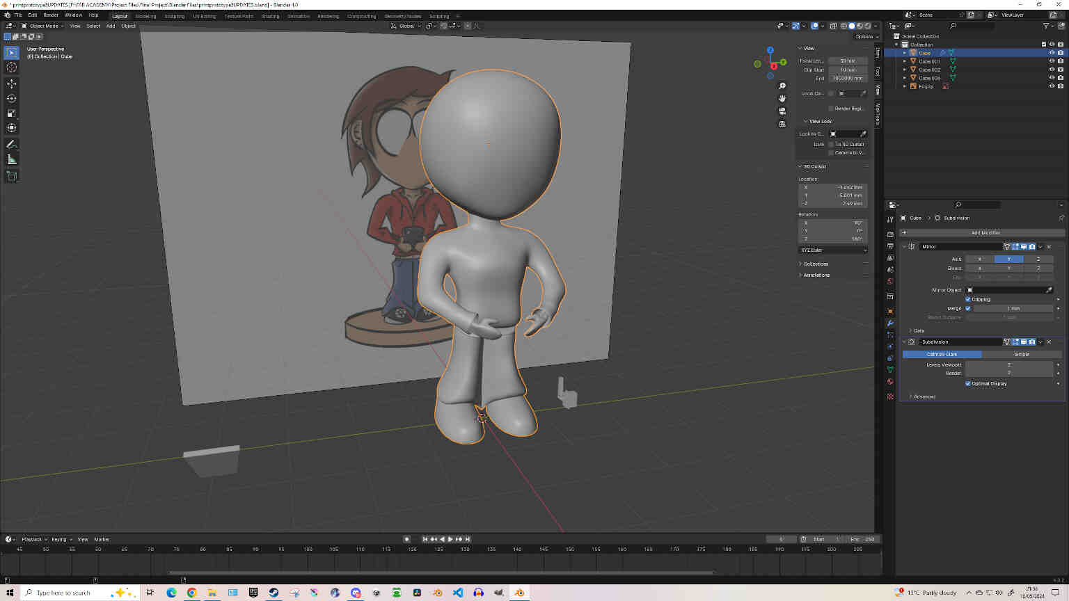
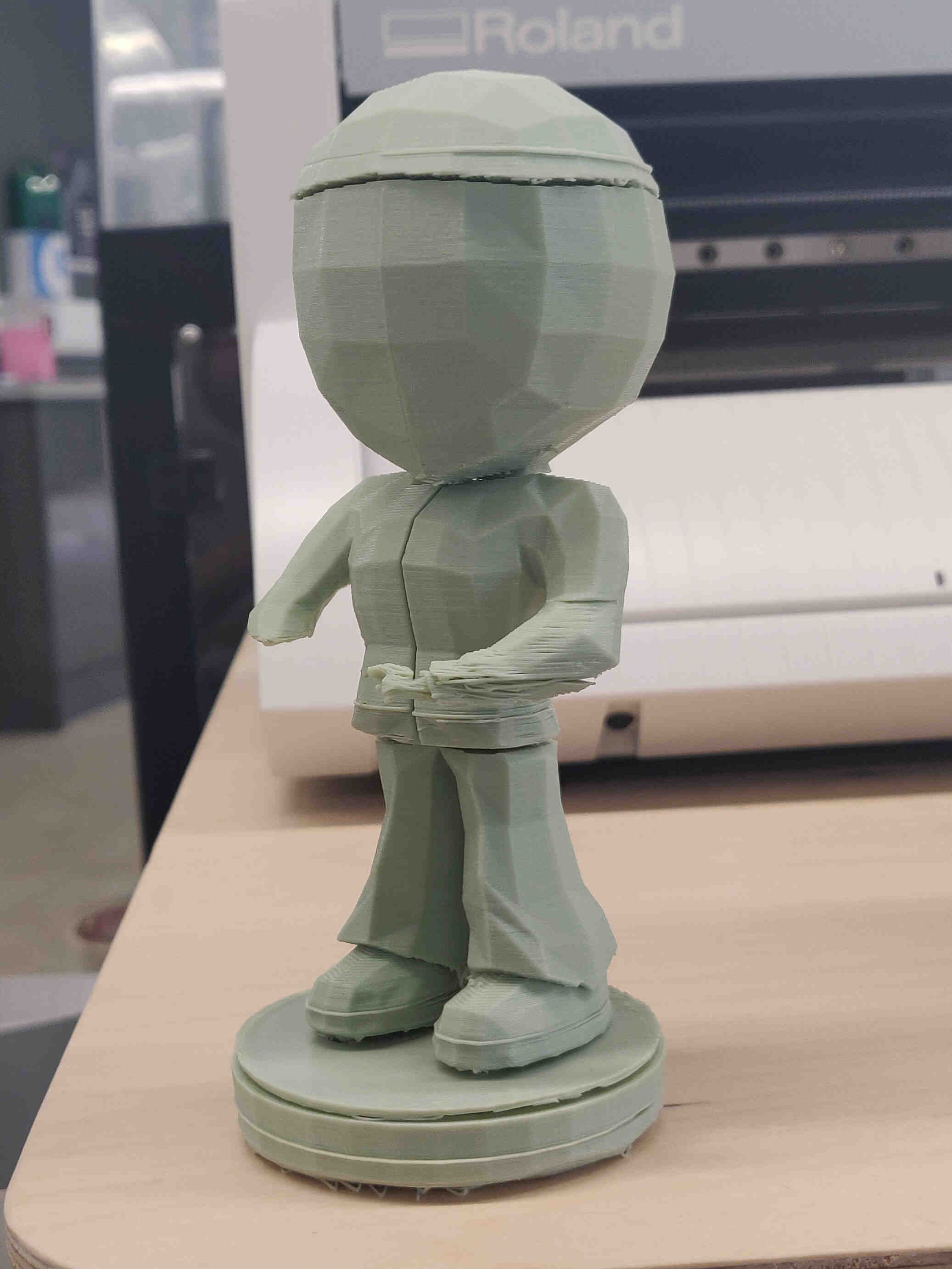
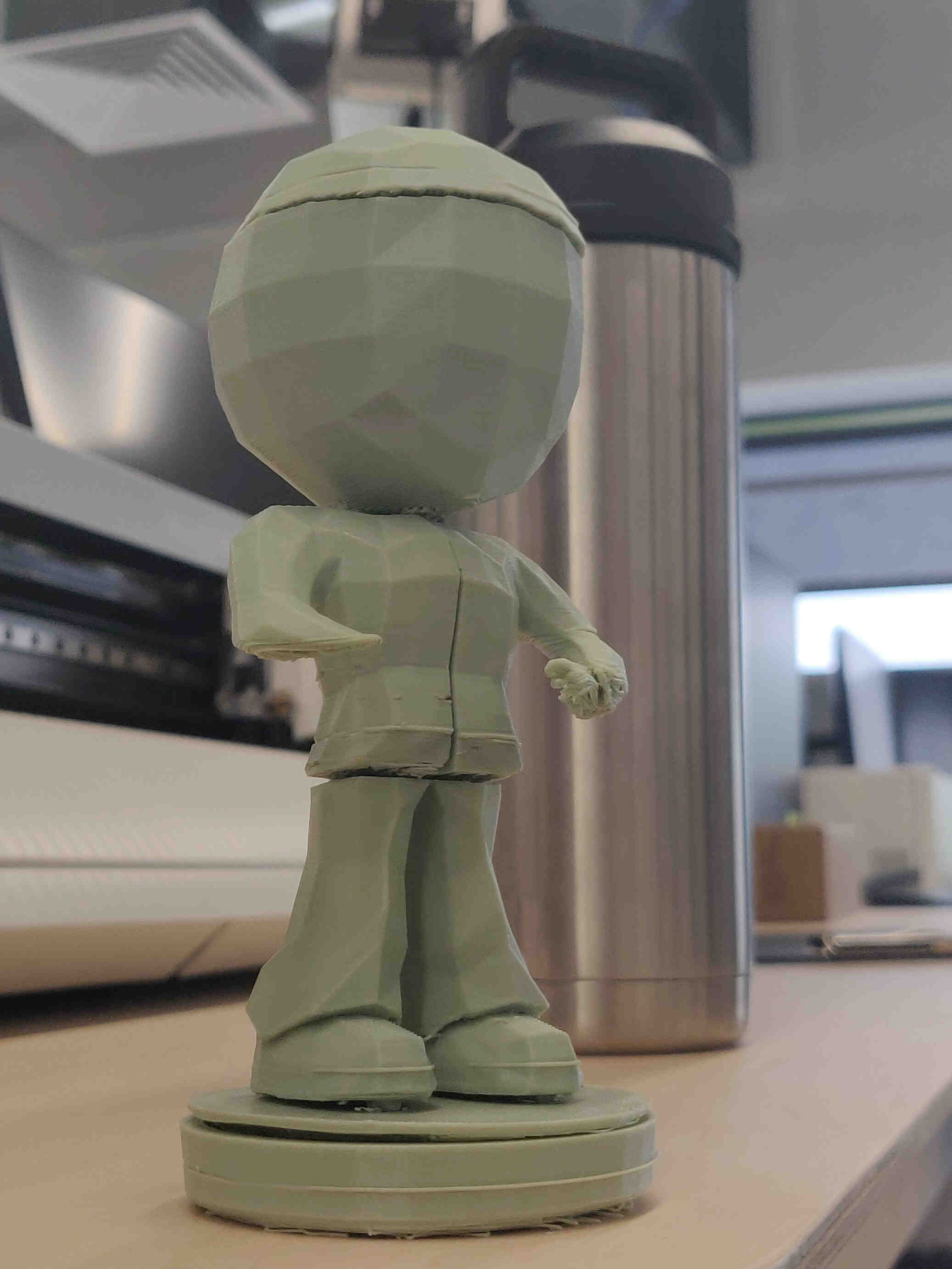
Little Buddy 3D Design Update
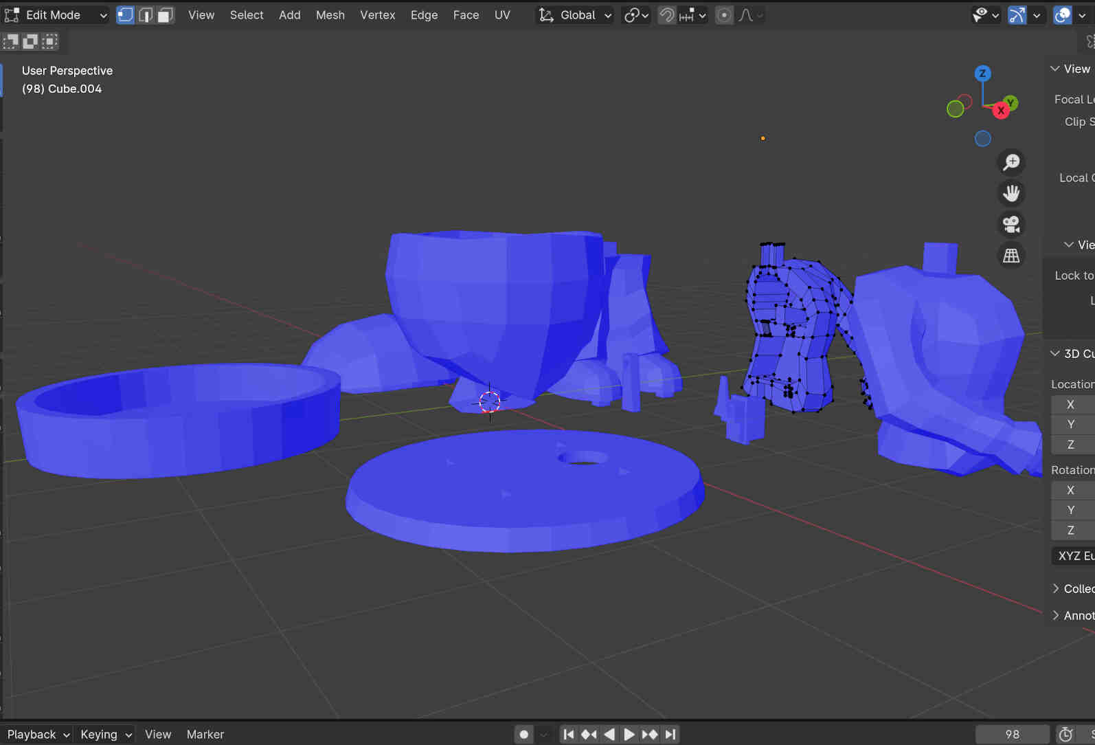
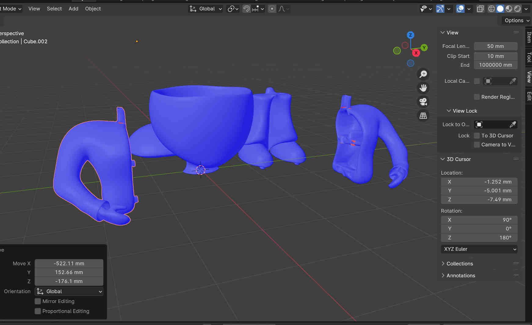
Updated design and topology, added more space around the chest and shoulders to make room for the Servo Motor. I debated whether to hollow the print out first or leave it until after I finished all the design elements. The reason for this worry is that I use Blender’s ‘proportional editing’ tool often, and I'm worried that it could upset the interior design and structure if the outer design is updated after the interior is done.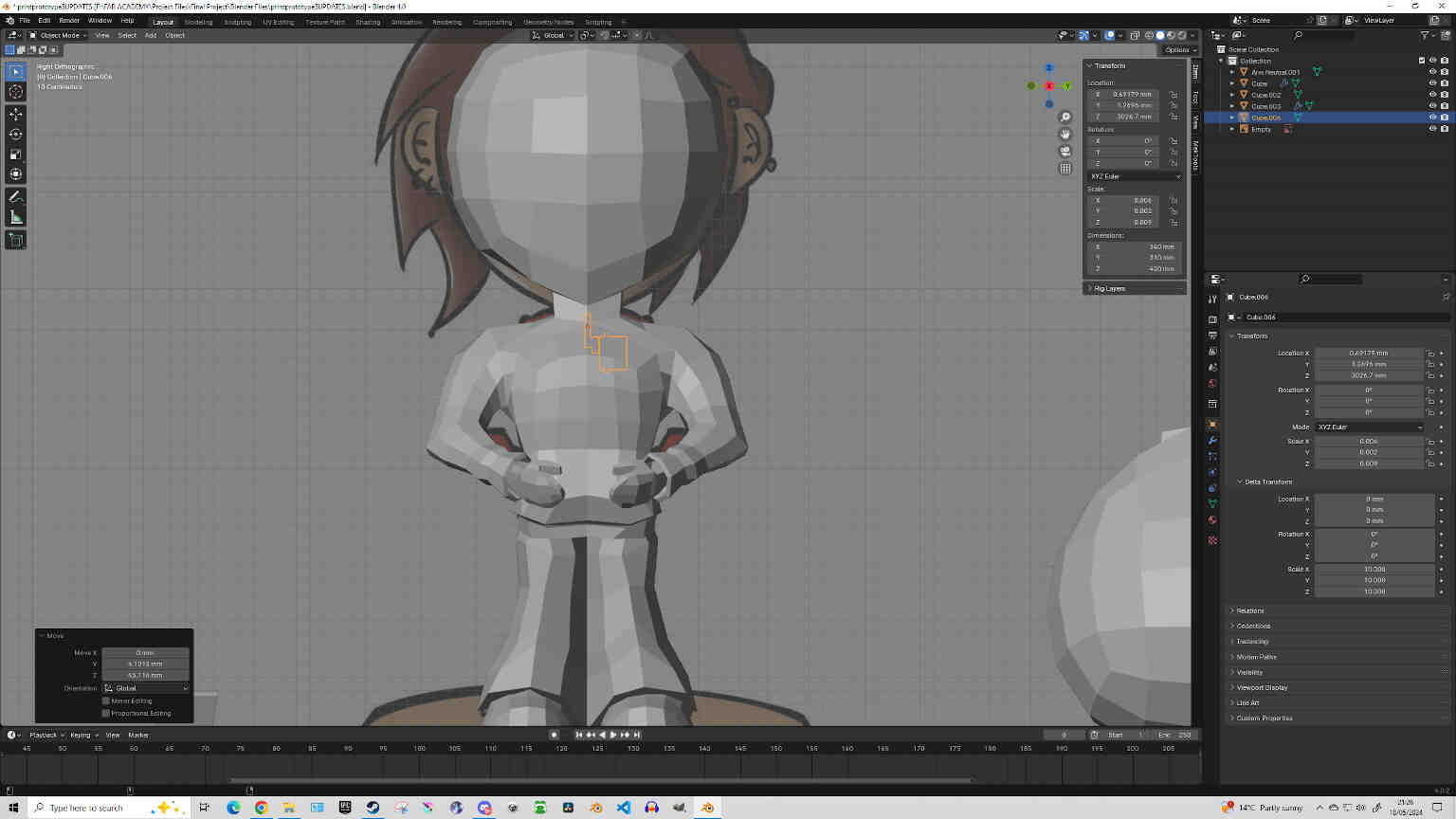
To get over this worry, I decided to take my Little Buddy Prototype, test hollowing-out, Separation & Keying techniques, then 3D print the result to see the print’s stability and give a rough feel of how it fits together.
Majority of the tools/modifiers I used:
Boolean, Mirror, Extrude, Merge (M), Inlay (I) and Separate by Parts (P).
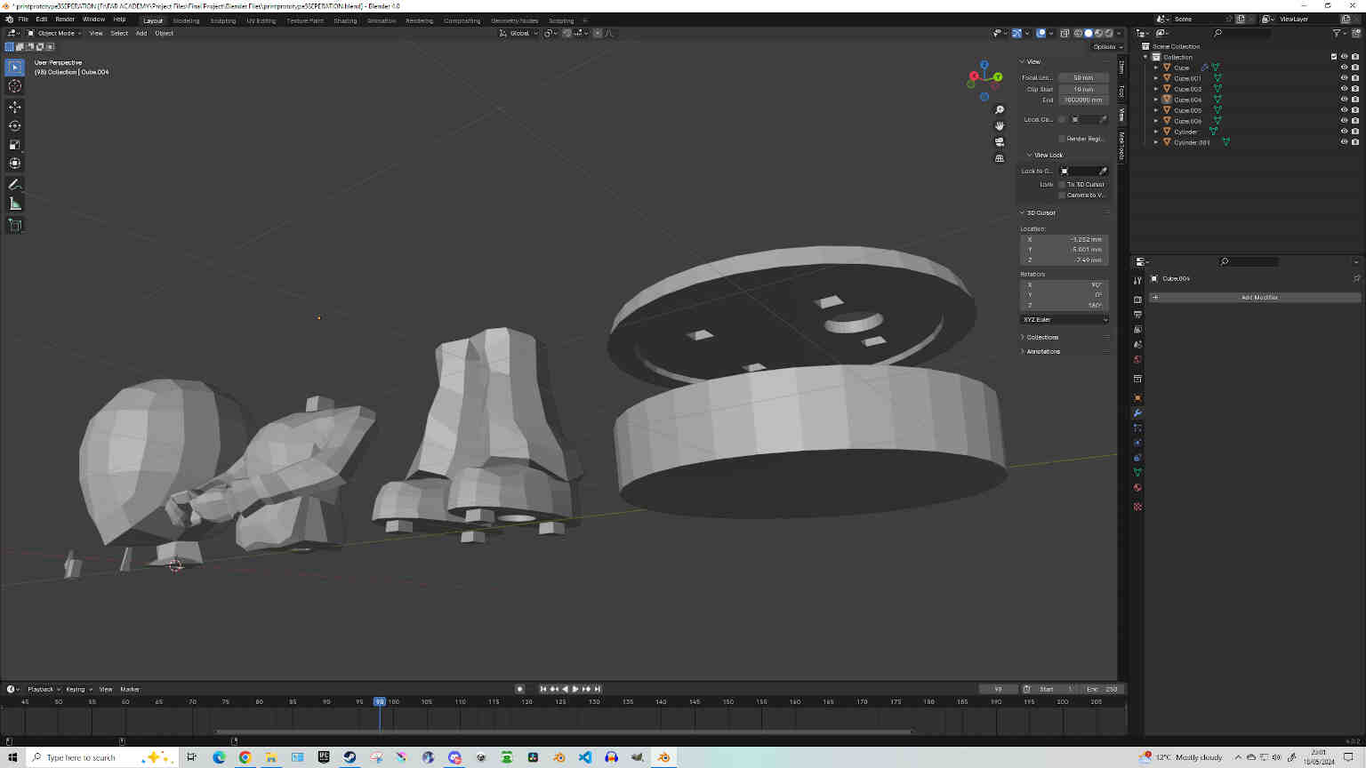
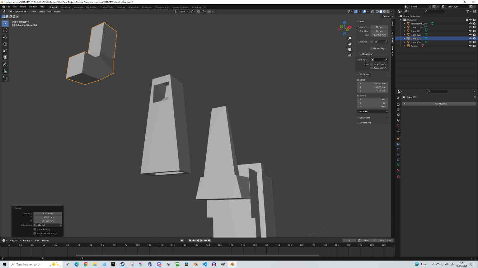
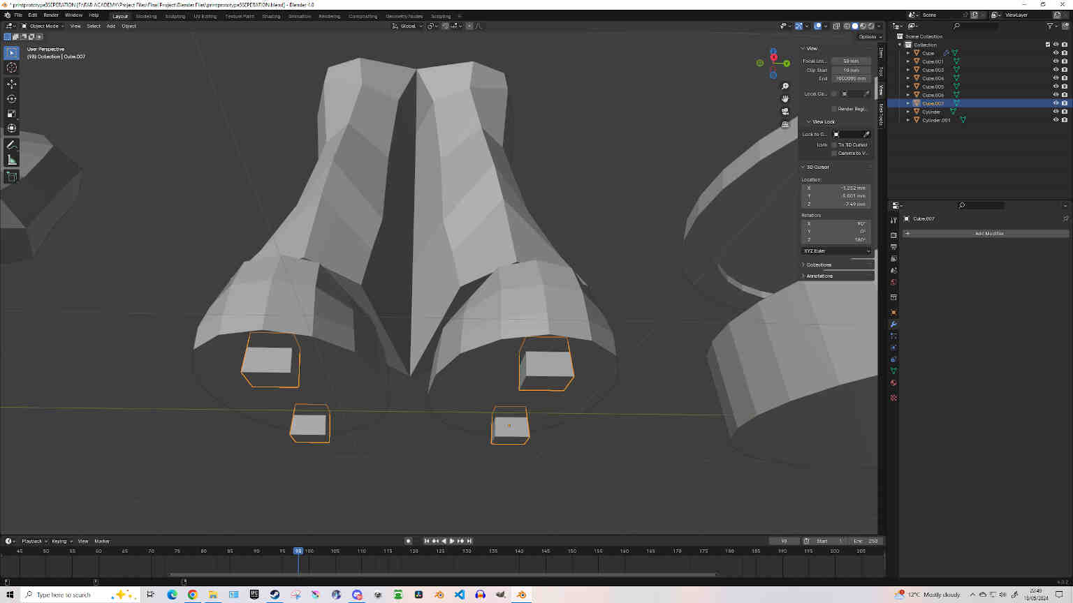
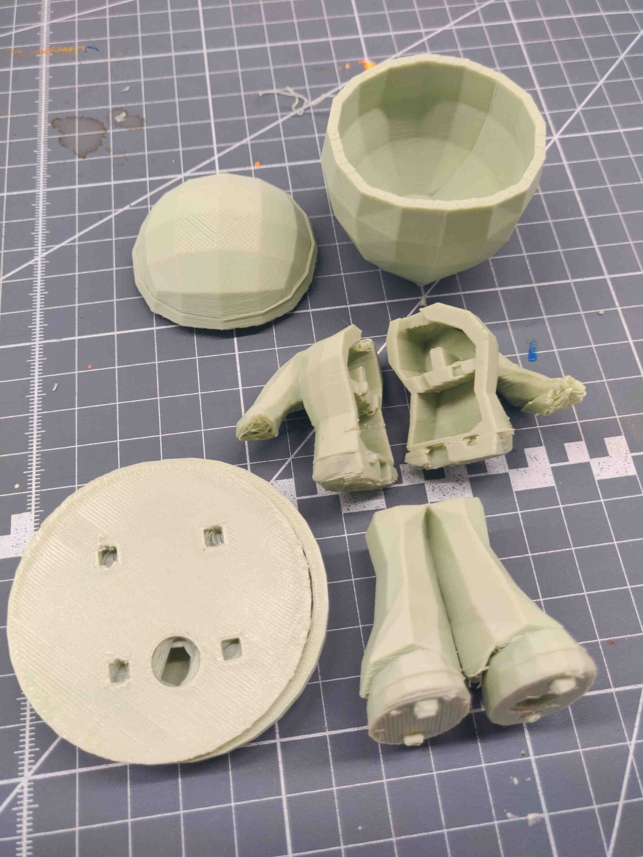
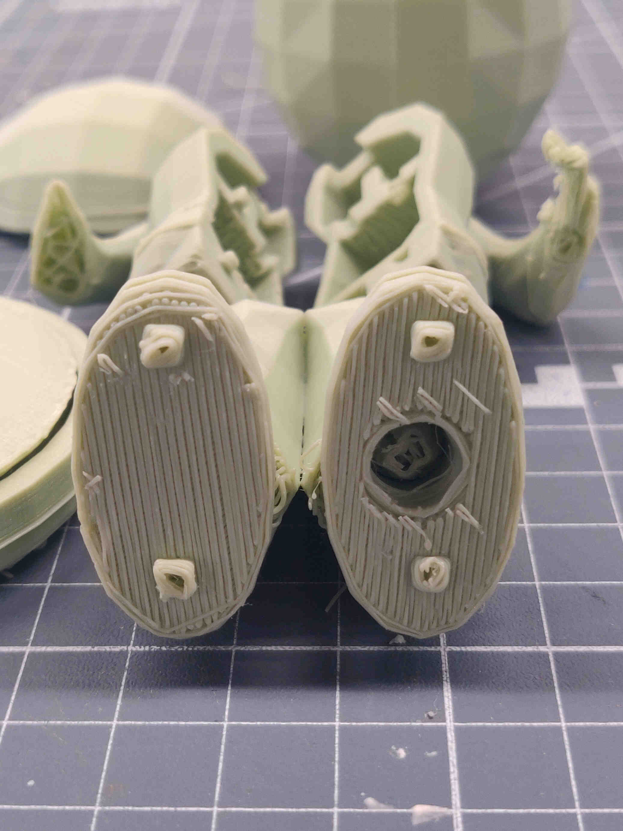
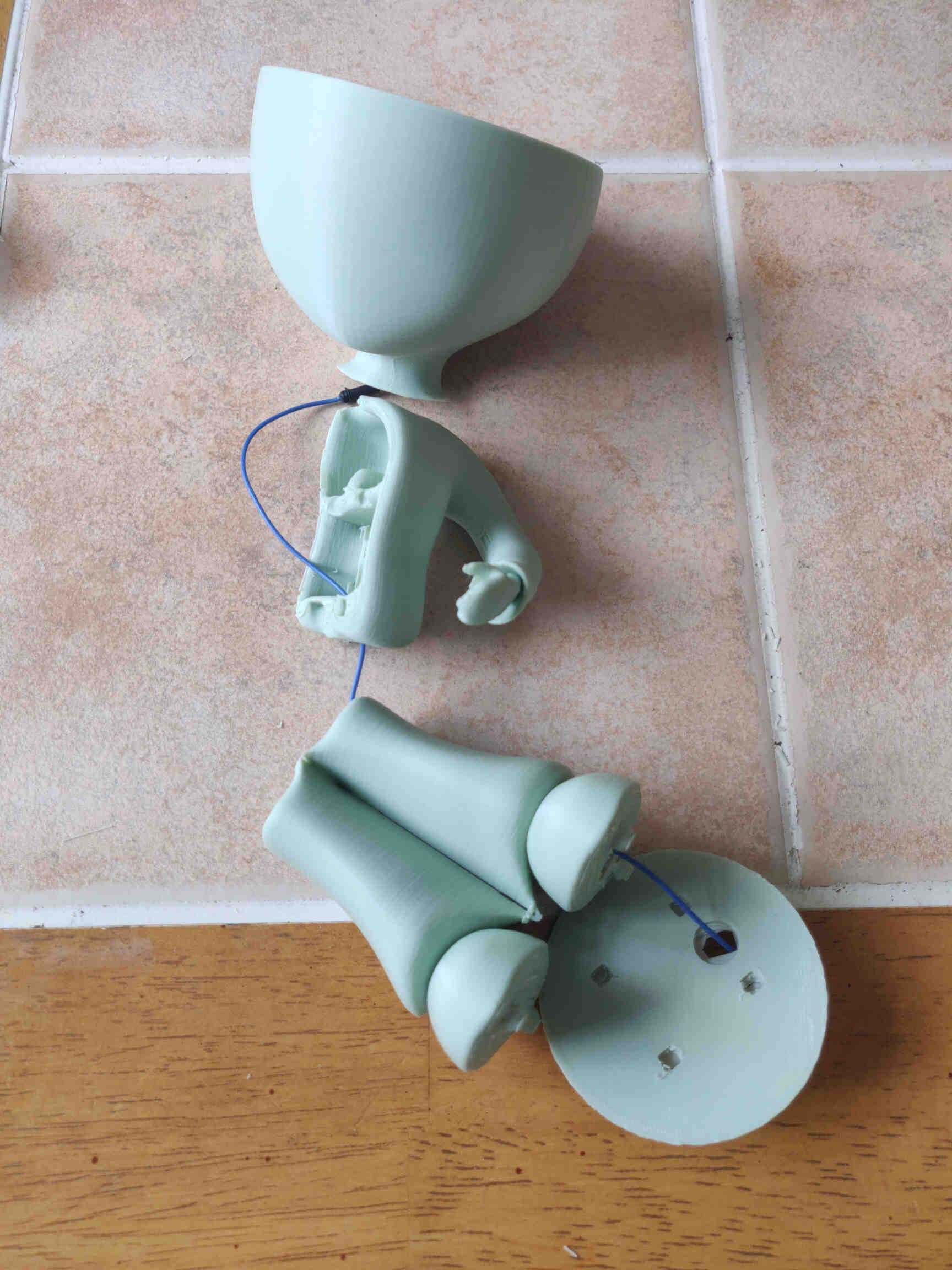
I separated the legs from the base, the chest from the waist, split the chest into two halves, separated the head from the chest and the top quarter of the head. I fixed any notable design/face orientation issues around the neck, chest & crotch, created a Base for the model to stand on and gave it a lid that has a slot for wiring under the right foot, as well as slots for keying. Next I added keys to the base, feet, waist, chest & neck using the Boolean Modifier (Difference/Union), then Tapered and Beveled the keys.
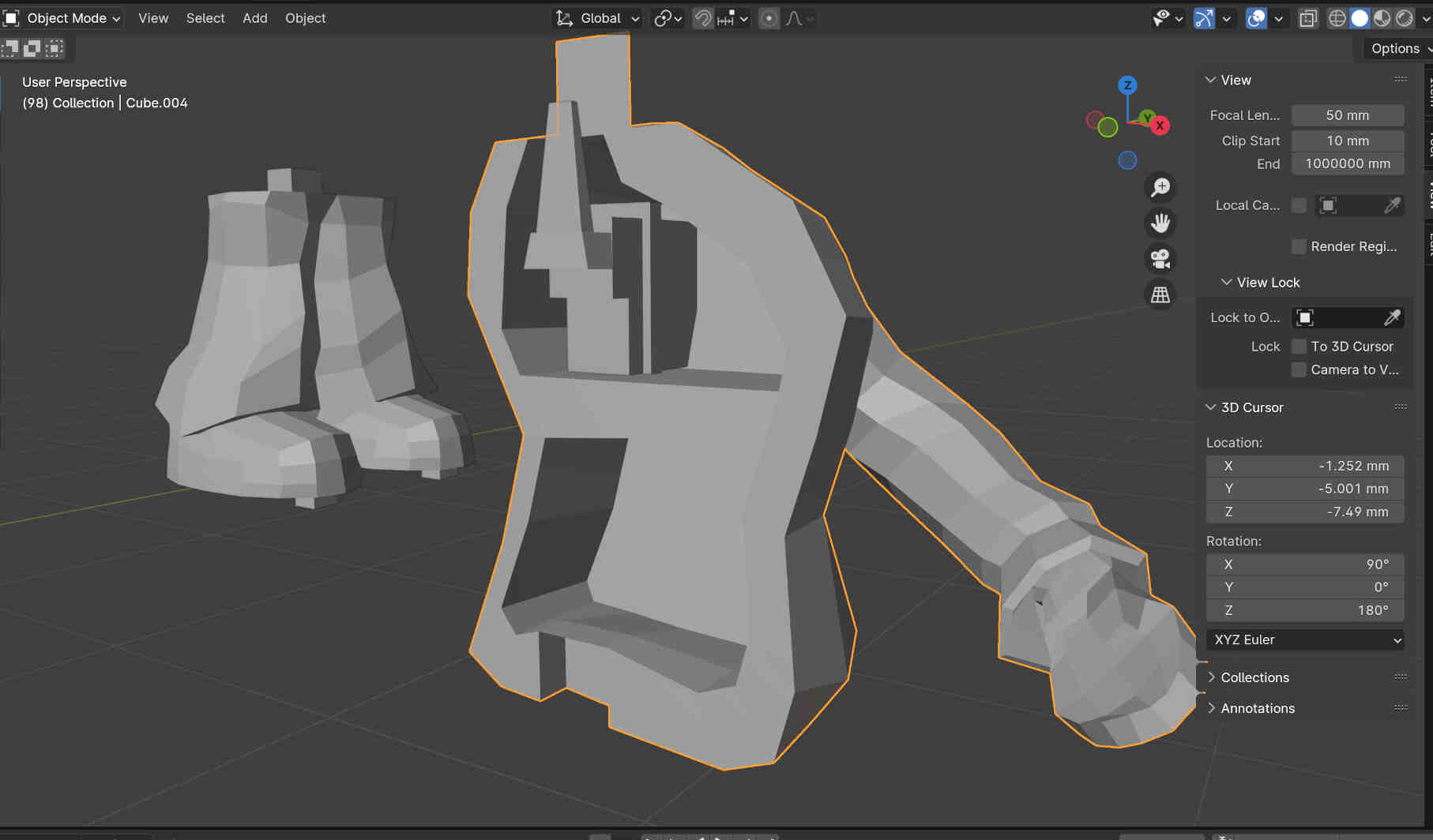
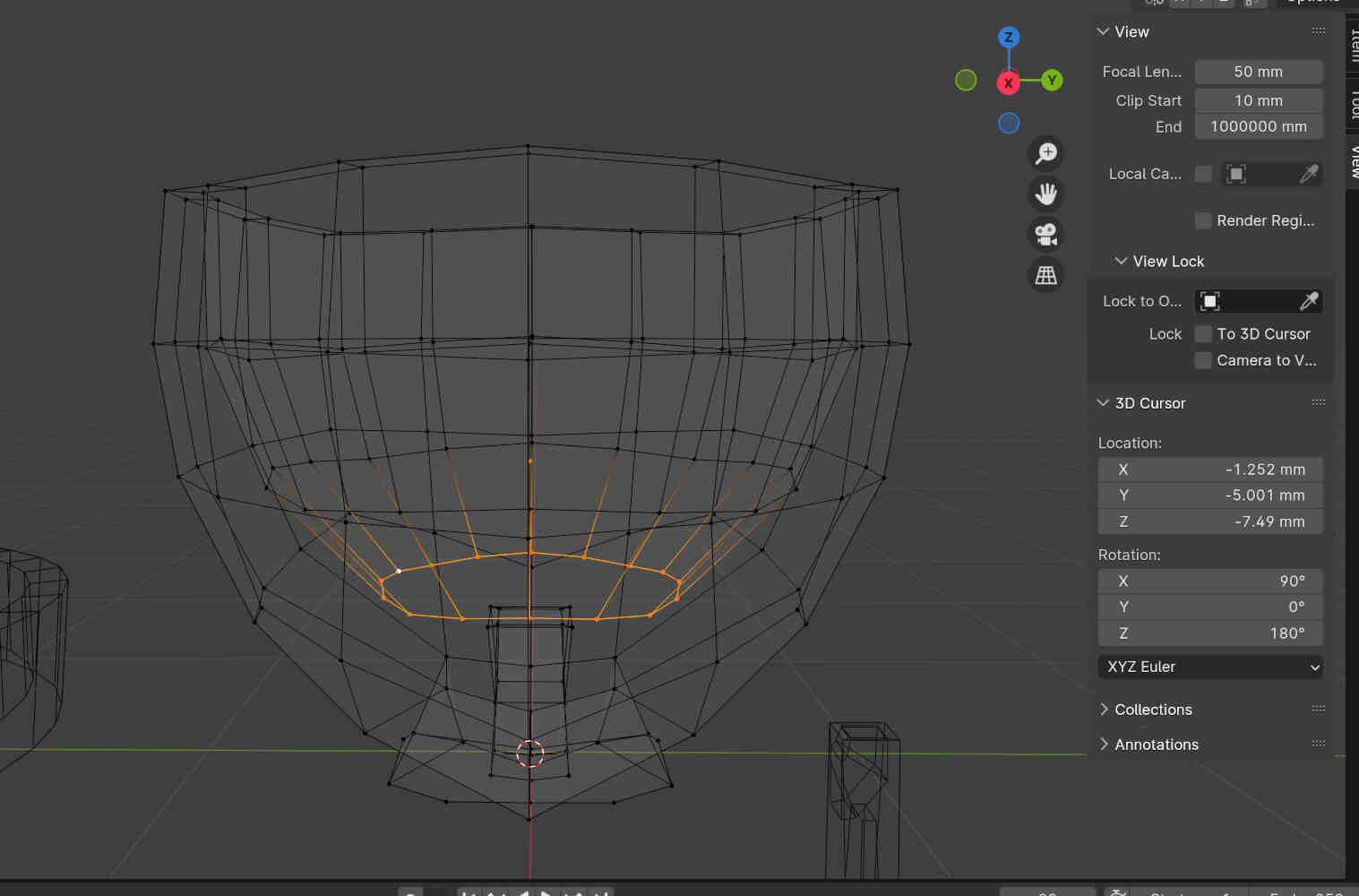
Designed servo / wiring extension for the neck, added a wiring tunnel that starts on the right side of the base that leads through the right leg, through the waist & chest, up through the neck and through the servo extension.
__________
Issues with the print:
As mentioned earlier, the first version of my new design finished printing at 3pm Tuesday after a couple printing issues. Printing issues were due to unnecessary supports being knocked over, interrupting the print layers and bed heating being too low for the new PLA material being used. (fixed by re-slicing, orienting objects appropriately, manually placing supports and raising the bed heating by 10 degrees via the Prusa Printer interface).
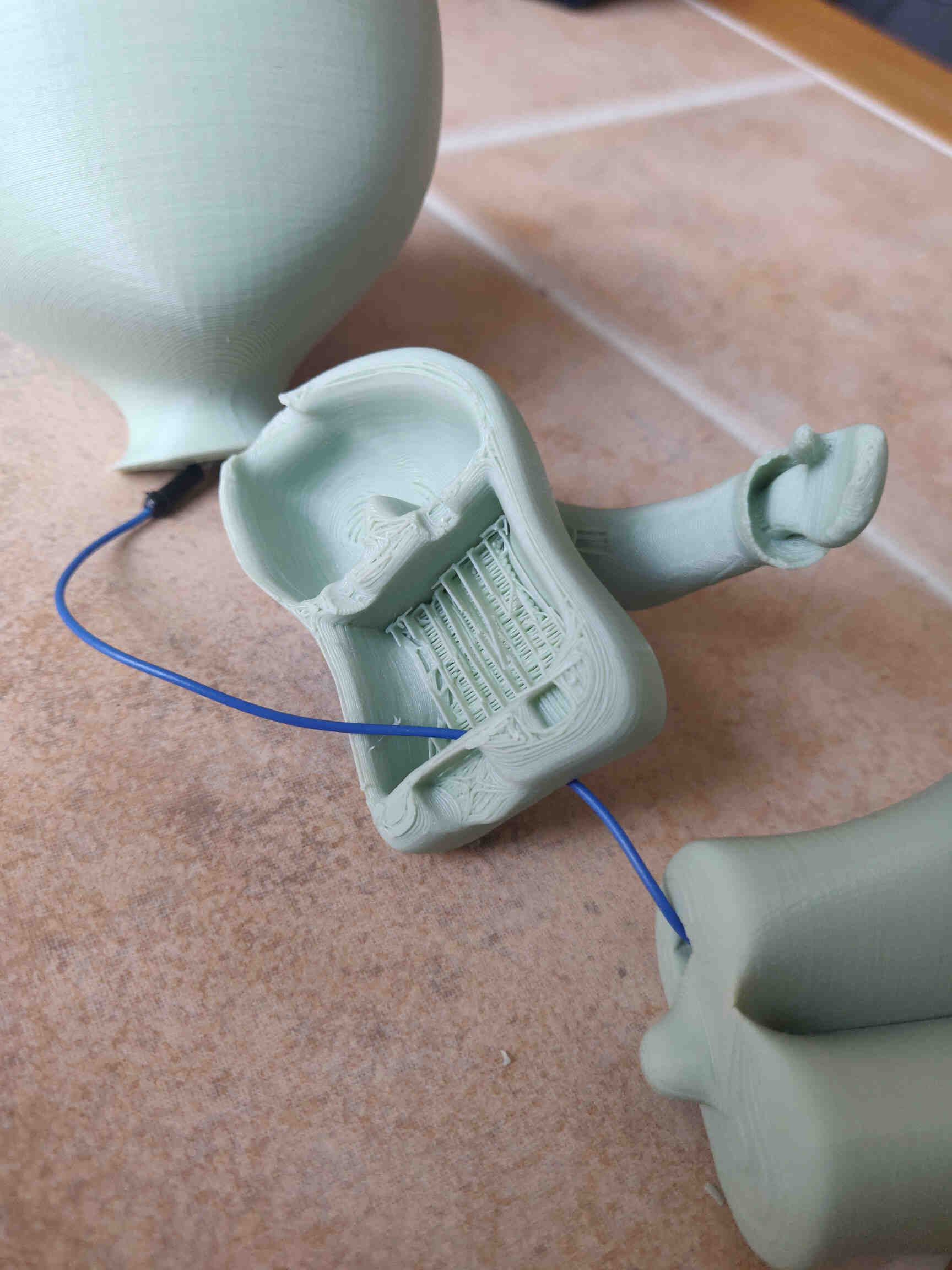
Issues with the print include hollowed out pieces having an unwanted layer filled in, most likely from using a boolean modifier to cut a hole in two connected objects. I don’t have a full explanation for why this happens, but I’ve experienced this issue on multiple prints before for this exact reason. This will need to be fixed as simply cutting through the hole in the Post-Processing stage is not desired.
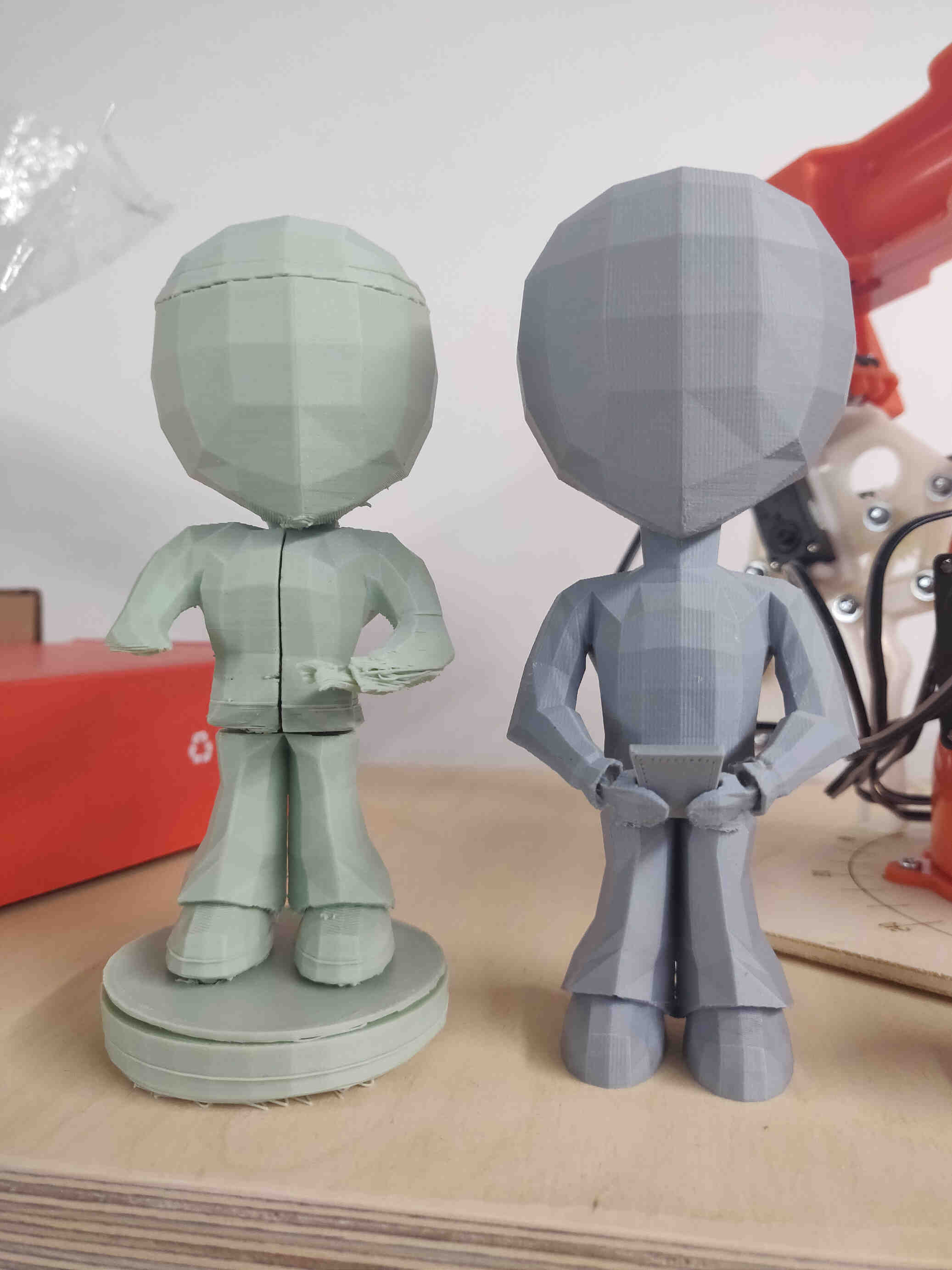
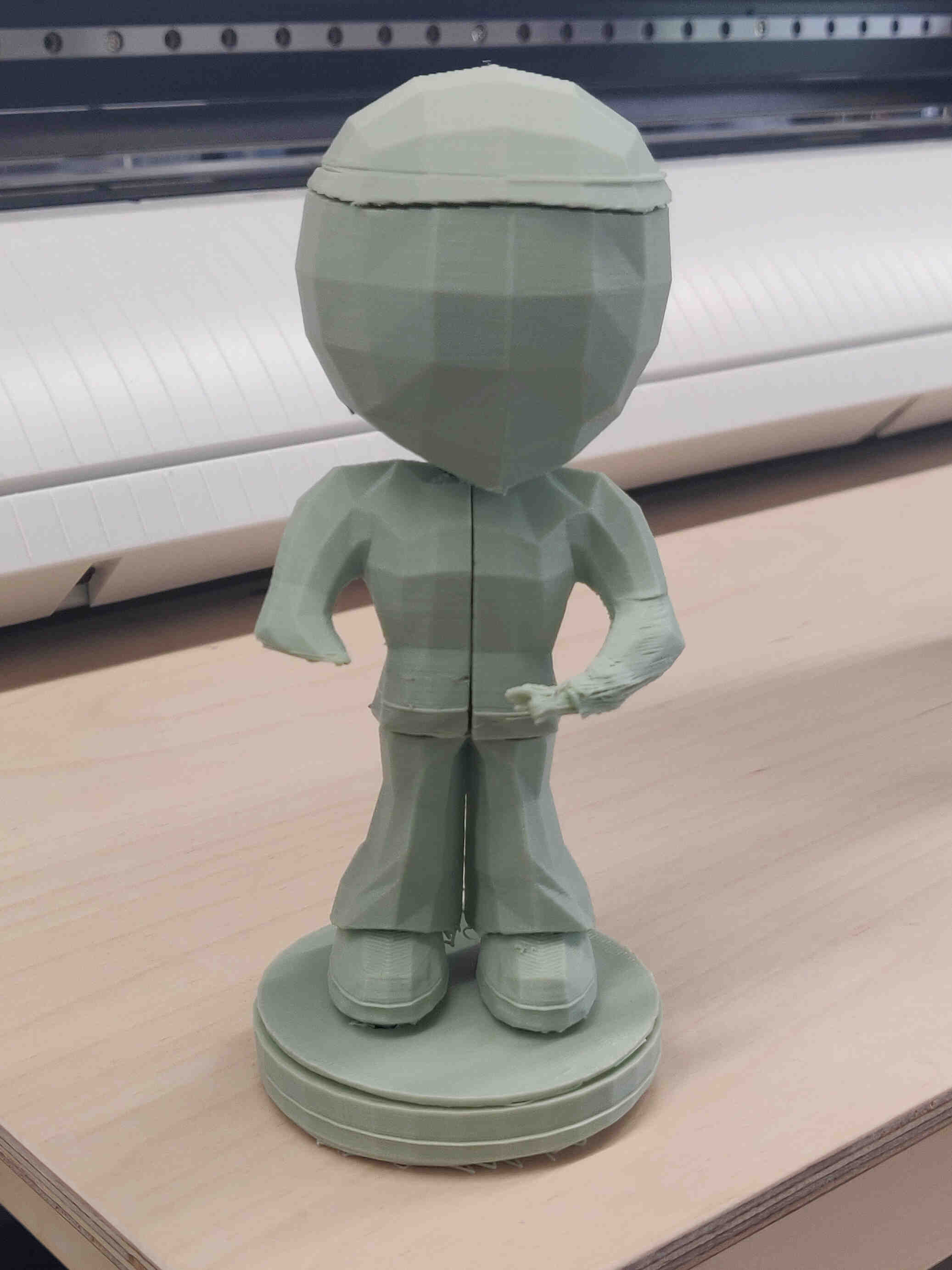
Before I left for the day, I setup a PLA print of the High Poly Prototype version at a larger size. This is more for sizing reference than anything else - I used a Subdivision Modifier over everything INCLUDING the keys and hollow cuts which will deform them completely, so I'm not expecting much in terms of perfect fitting. But I was also very curious on what the High Poly print result would be. Below is the final image I could get before I had to wrap up and update the website for System Integration week. (Result of High Poly Print is now below!)
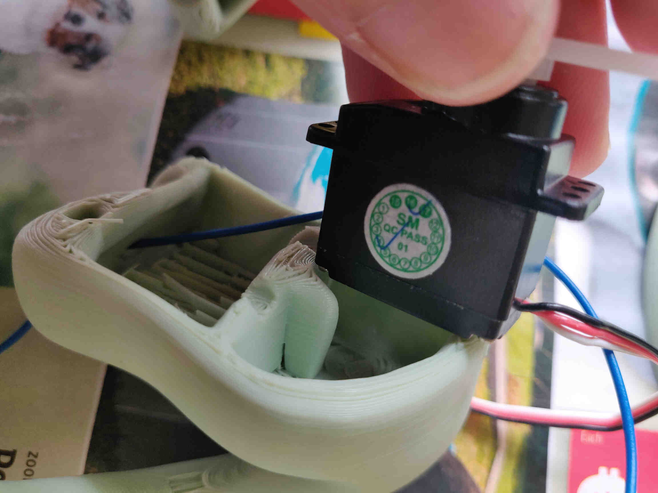
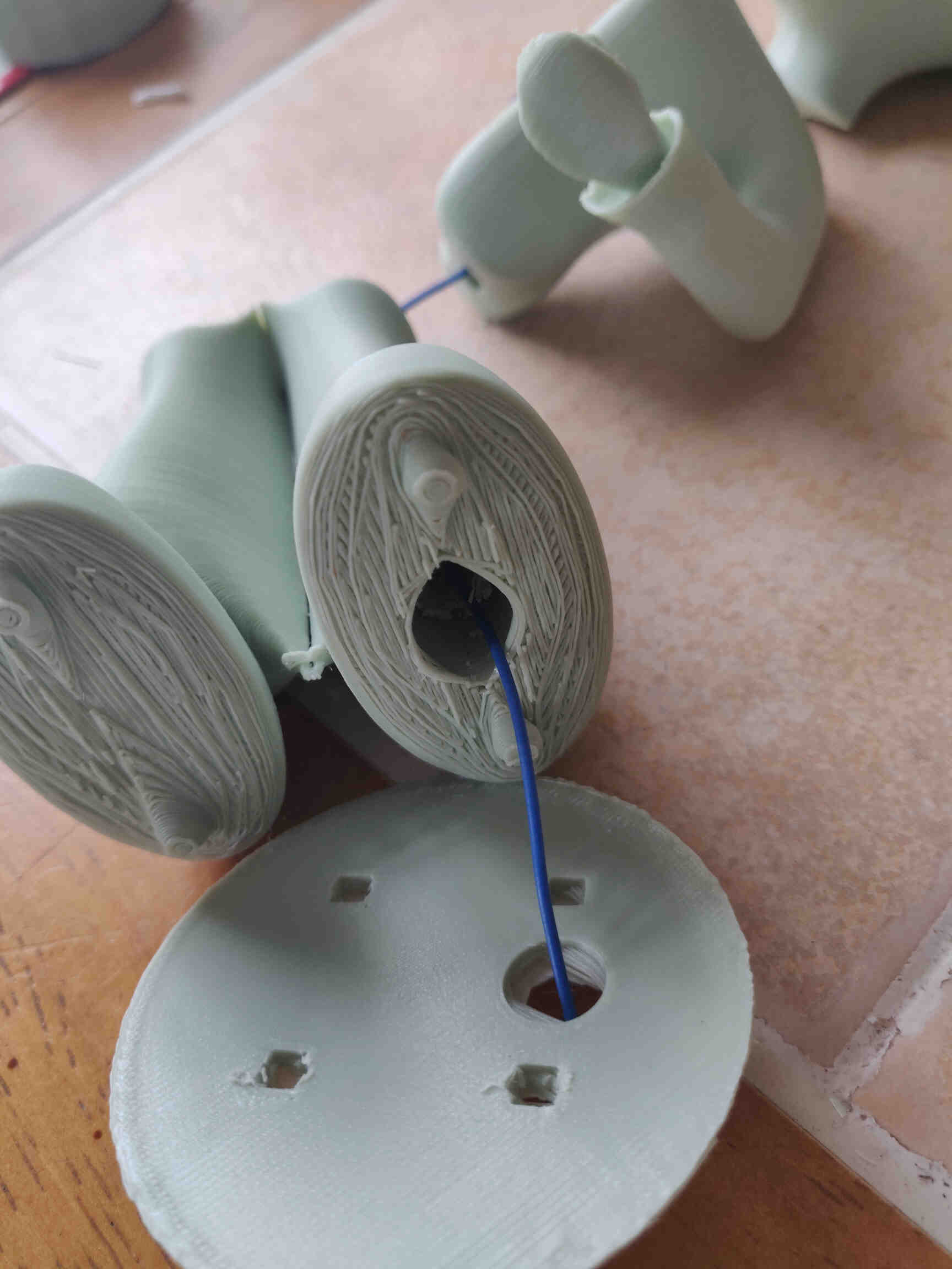
High Poly Model and Wiring Integration:
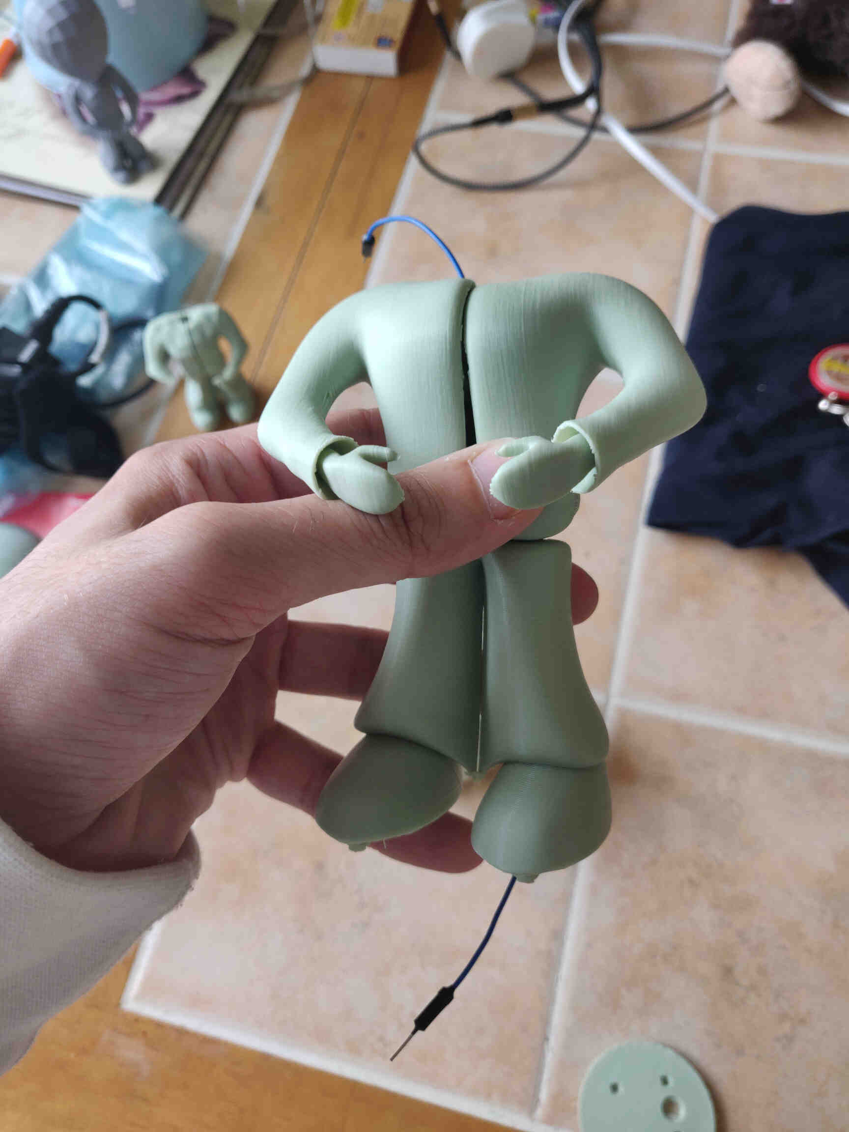
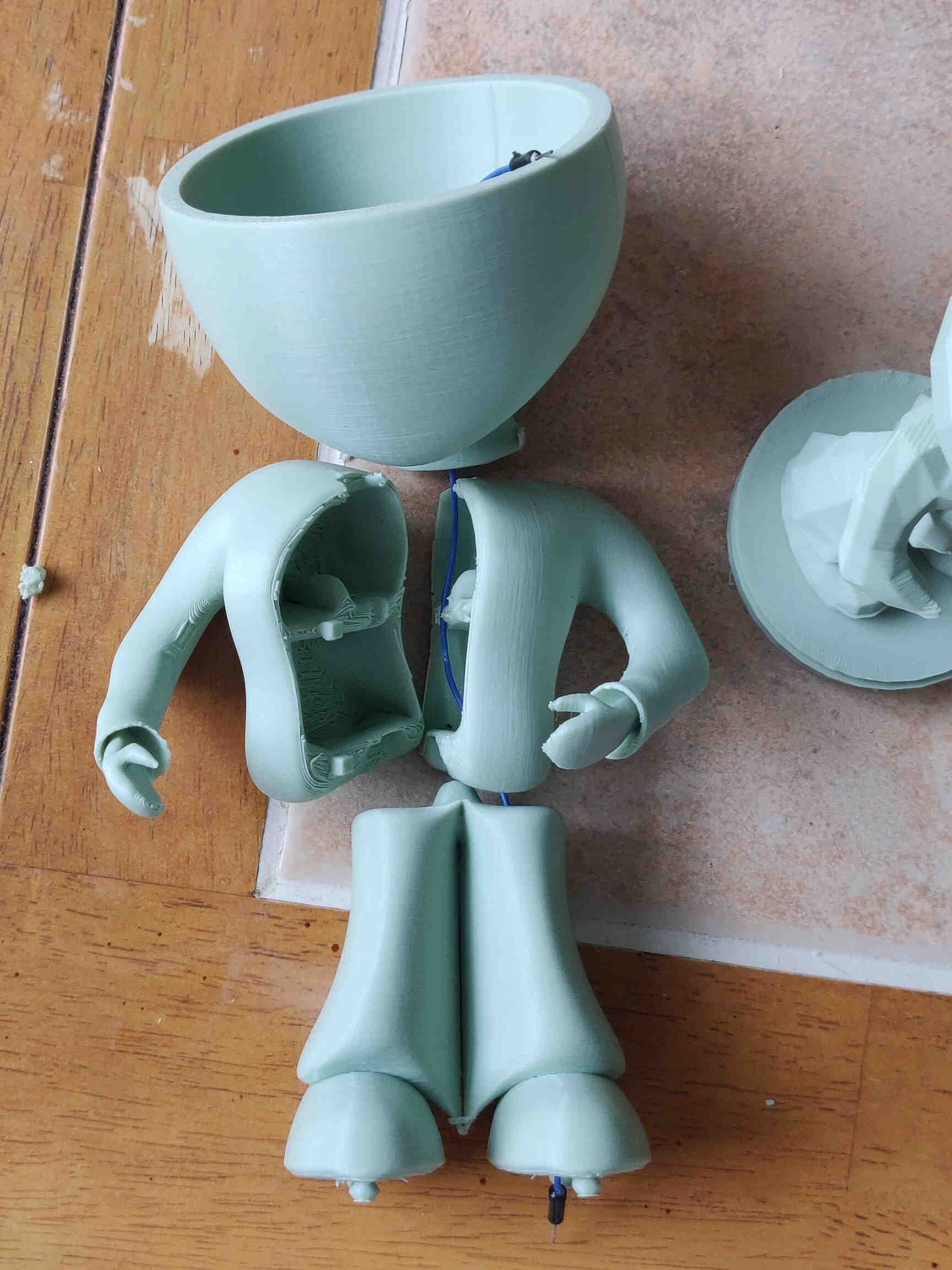
I was happy with the wire fitting (though a few adjustments needed to be made in the future) but sorely disappointed with just how much further I have to go before I get the correct measurements to fit the servo. For context, Blender is pretty unreliable with measurements, even after changing settings and preferences. The issue being that when you bring the model into Slice software, it ends up being very small. Our fablab technician recommended I just multiply the size of the model by 10 once it's in slice software, so I'll attempt that next time.
Although the High Poly Print was a rush job, it came out super smoothly. Still, it's undeniable that I much prefer the Low Poly version as it reminds me of the ol' Playstation 1 days and my time as a gamer - so I'm going to push forward with a Low Poly model for my Final Project.
__________
Circuit Board Design Research
After researching the type of traces / PCB designs needed for my final project to use a VL53L1X ToF Sensor, a Servo Motor and an LED. I was understanding the basics after everything I've learned through debugging, but I was still feeling overwhelmed. A friend offered to ask ChatGPT for a general reference on the whole structure, and I was inclined to agree.
So I asked ChatGPT “How to make a circuit board using a Seeed Studio Xiao RO2040 that works with a VL53L1X time of flight sensor, a servo motor and an LED light?”
Once again I'm blown away by ChatGPT’s range, responsiveness and sense of understanding on the subject - but most of all, how clearly I can understand it.
It's worth noting that if I paid for ChatGPT4.0, it would most likely have given me diagrams to either download or view for better understanding. Times like these, the subscription is really tempting.
On one hand you could argue that I should gain a full understanding of traces and components and follow the research & design process. On the other hand, it could be more reliable than my inexperienced brain and lend me much more time to focus on the processes I like, such as 3D Modeling.
Either way, I'm finding more useful ways to integrate AI into my own work in the future, which is either a positive or negative step. Only time will tell for generations to come.
__________
ChatGPT’s response (v3.5, 19th May, 2024)
To create a circuit board using the Seeed Studio Xiao RP2040 that works with a VL53L1X time-of-flight sensor, a servo motor, and an LED light, follow these steps: Materials Needed:1. Seeed Studio Xiao RP2040
2. VL53L1X Time-of-Flight Sensor
3. Servo Motor
4. LED Light
5. Resistors (for the LED, typically 220Ω)
6. Capacitors (if needed for debouncing or power stabilization)
7. Breadboard and Jumper Wires (for prototyping)
8. PCB Design Software (e.g., KiCad, Eagle)
9. Power Supply (appropriate voltage and current rating for the servo and sensor)
10. Soldering Kit (soldering iron, solder, flux)
Steps:
1. Schematic Design
Create a schematic diagram using PCB design software.
- Microcontroller (Xiao RP2040):
- VCC to 3.3V
- GND to ground
- Assign pins for the VL53L1X, servo motor, and LED.
- VL53L1X Sensor:
- VCC to 3.3V (ensure compatibility with the Xiao RP2040)
- GND to ground
- SDA to an I2C data pin (e.g., pin 2 on Xiao RP2040)
- SCL to an I2C clock pin (e.g., pin 3 on Xiao RP2040)
- Servo Motor:
- VCC to the appropriate voltage (usually 5V, use an external power supply if needed)
- GND to ground
- Signal pin to a PWM-capable pin on the Xiao RP2040 (e.g., pin 6)
- LED:
- Connect a 220Ω resistor in series with the LED to limit current
- Anode (long leg) to a digital output pin on the Xiao RP2040 (e.g., pin 7)
- Cathode (short leg) to ground
2. Breadboard Prototyping
Before creating a PCB, prototype the circuit on a breadboard to ensure functionality.
1. Connect the VL53L1X Sensor to the Xiao RP2040.
2. Connect the Servo Motor to the Xiao RP2040 and power supply.
3. Connect the LED with the resistor to the Xiao RP2040.
4. Upload Code to the Xiao RP2040 to test the sensor, control the servo, and blink the LED.
3. PCB Layout
Using PCB design software, create the layout:
1. Place Components: Arrange the components on the board.
2. Route Traces: Connect the components with traces according to the schematic.
3. Add Ground and Power Planes: Ensure stable power distribution.
4. Verify Design Rules: Check for any errors or potential issues.
4. Fabricate the PCB
Send the design files (Gerber files) to a PCB manufacturer.
5. Assemble the PCB
Once you receive the fabricated PCB, solder the components onto the board.
Example Code (Seeed Studio Xiao RP2040)
Here’s a simple example code to interface the VL53L1X, control a servo motor, and blink an LED using Seeed Studio Xiao RP2040:
  #include
  #include
  #include

  Adafruit_VL53L1X vl53 = Adafruit_VL53L1X();
  Servo myServo;
  const int ledPin = 7;

  void setup() {
    Serial.begin(115200);
    Wire.begin();

    if (!vl53.begin()) {
      Serial.println("Failed to detect and initialize sensor!");
      while (1);
    }
    vl53.startRanging();

    myServo.attach(6); // Attach servo to pin 6
    pinMode(ledPin, OUTPUT);
  }

  void loop() {
    int distance = vl53.read();
    Serial.print("Distance: ");
    Serial.println(distance);

    if (distance < 500) { // Example condition
      digitalWrite(ledPin, HIGH); // Turn on LED
      myServo.write(180); // Rotate servo to 180 degrees
    } else {
      digitalWrite(ledPin, LOW); // Turn off LED
      myServo.write(0); // Rotate servo to 0 degrees
    }
    delay(100);
  }
Tips:
- Power Management: Ensure that the power supply can handle the current requirements of the servo motor.
- I2C Pull-up Resistors: VL53L1X may require pull-up resistors on SDA and SCL lines if they are not built-in.
- Debugging: Use serial output to debug and verify sensor readings and component states.
By following these steps, you can design and build a circuit board that interfaces the VL53L1X time-of-flight sensor, controls a servo motor, and operates an LED light with the Seeed Studio Xiao RP2040. - (Written by ChatGPT v4o, 19th May 2024)
__________
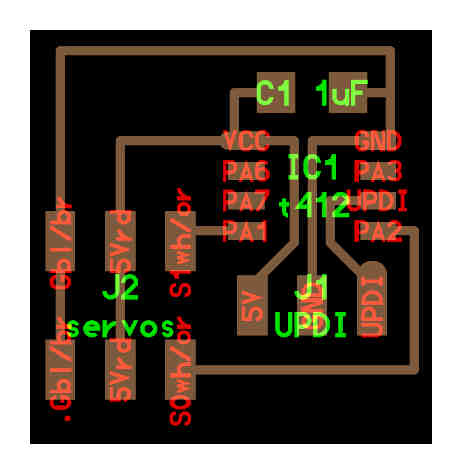
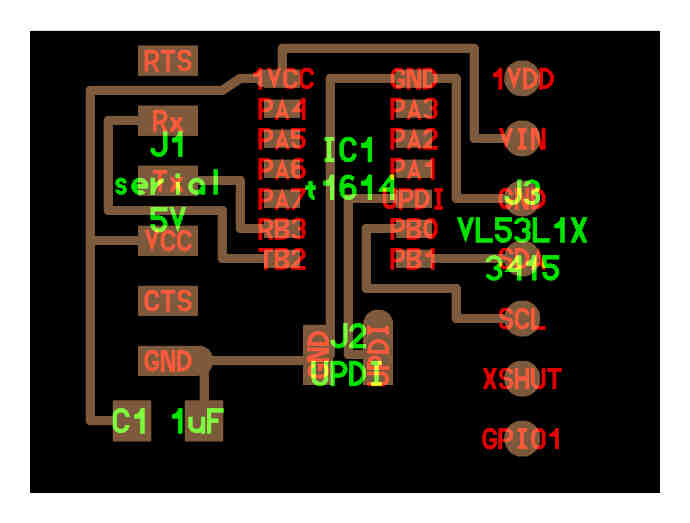
Circuit Board Concepting and Integration
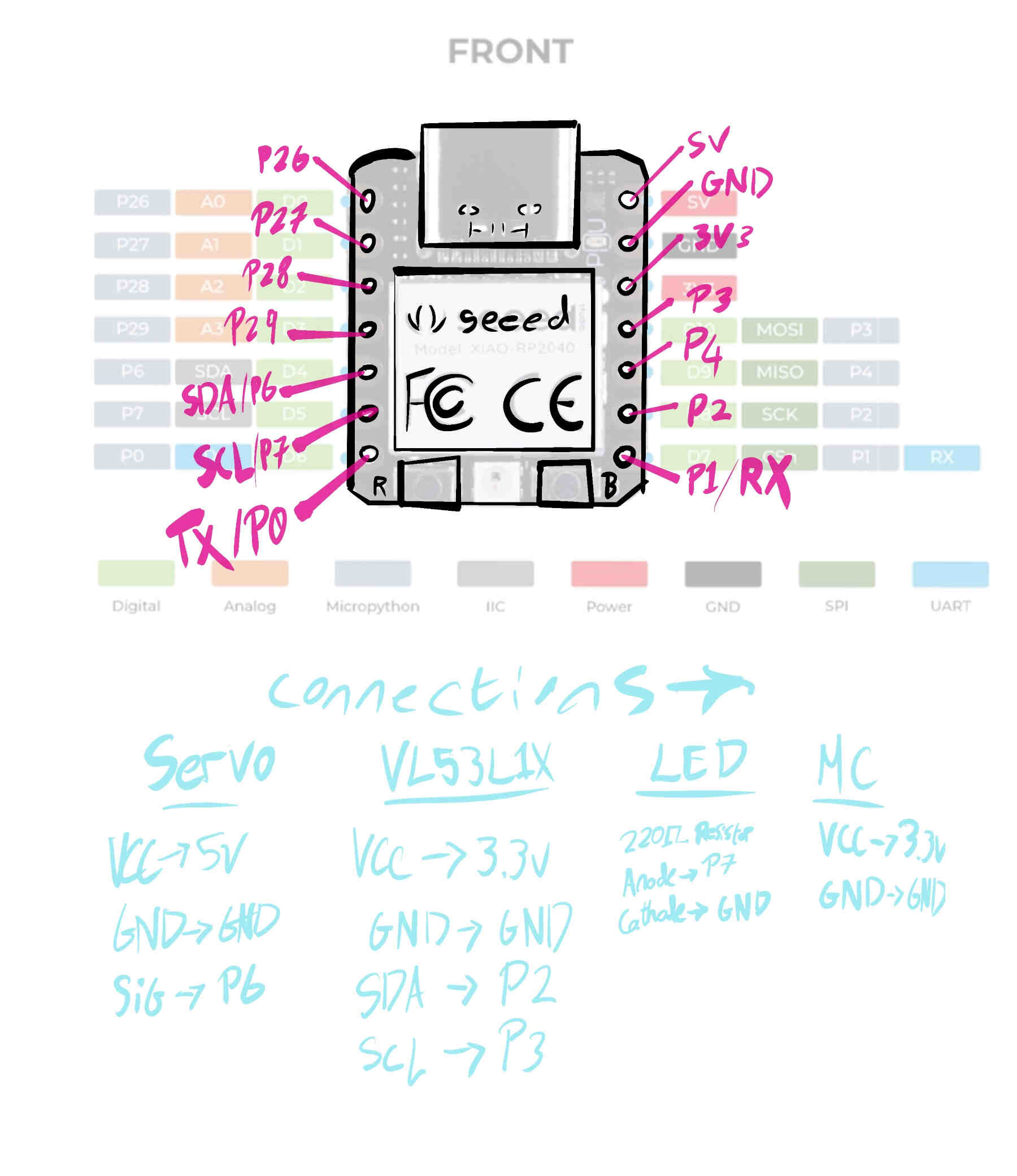
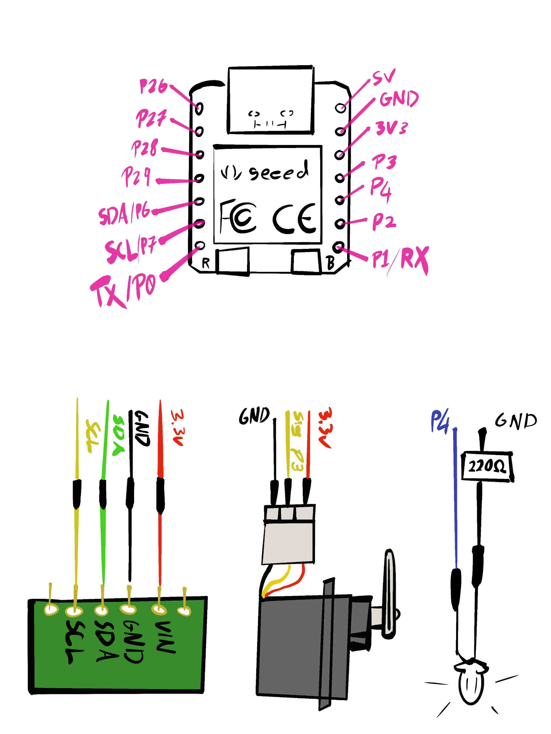
I spent a full day trying to understand how to design a PCB that integrates all of my final project needs. To do this in a way I understand is to draw it out in basic steps. As you can see from the images below, I went into Procreate and drew out an illustration of the Seeed Studio Xiao RP2040, VL53L1X Time of Flight, LED & a Servo Motor. Then I wrote out all the connections I needed to make and their pathways.

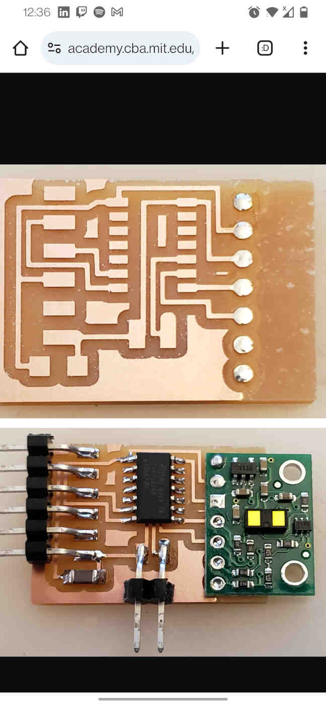
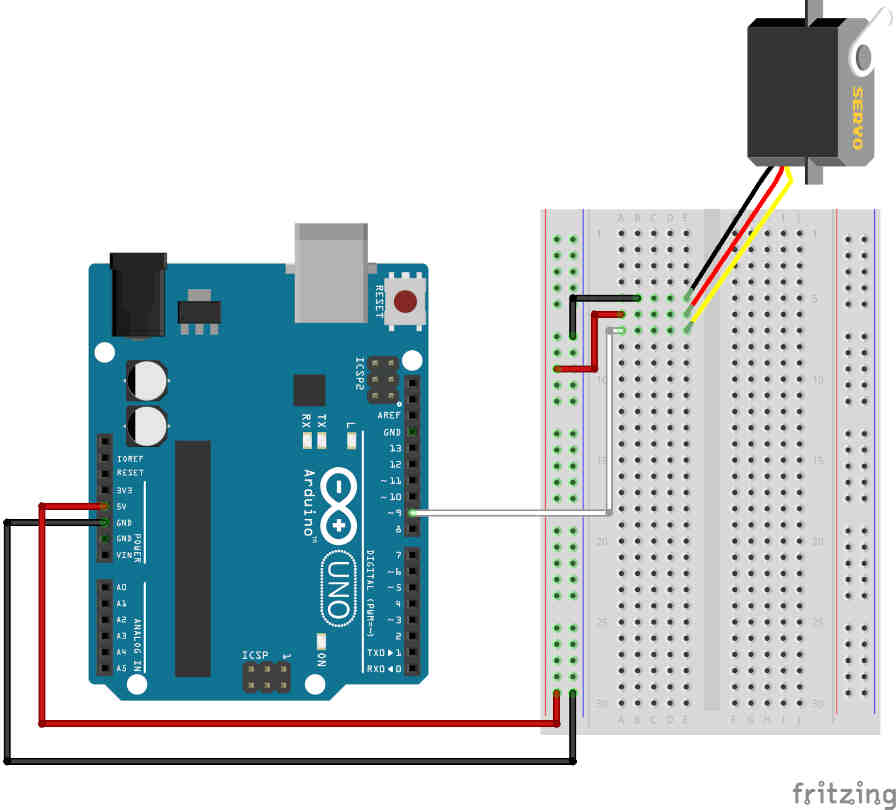
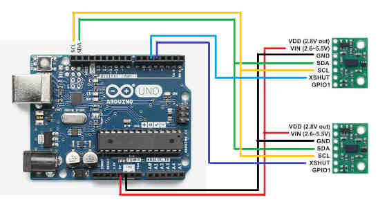
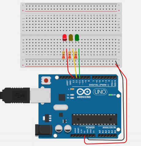
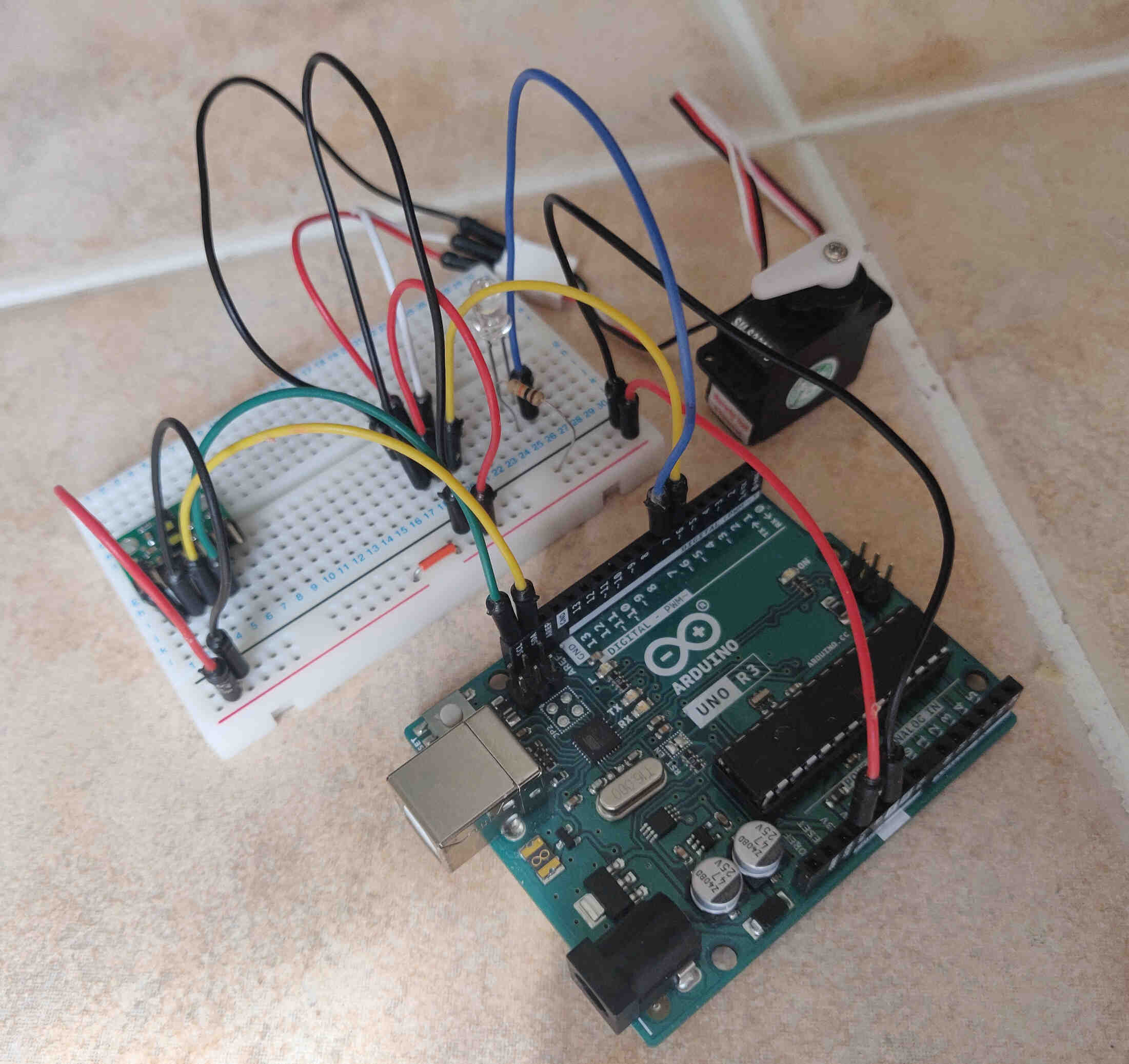
I struggled to find the right pathways and traces, so I took out my Arduino, Breadboard and components, then looked on Google Images for diagrams of Servo connections, LED connections and Below you can see the diagrams I referenced and the wiring I made to house all of these components.
Once that was done I spent some time in Procreate designing the traces and how the PCB board will be laid out and fitted into the base. Overall I’m impressed that I was able to do this as I struggled with electronics all the way through Fab Academy, showing just how far I’ve come - especially since I didn’t know how a circuit board worked at all before Week 4 into Fab Academy.
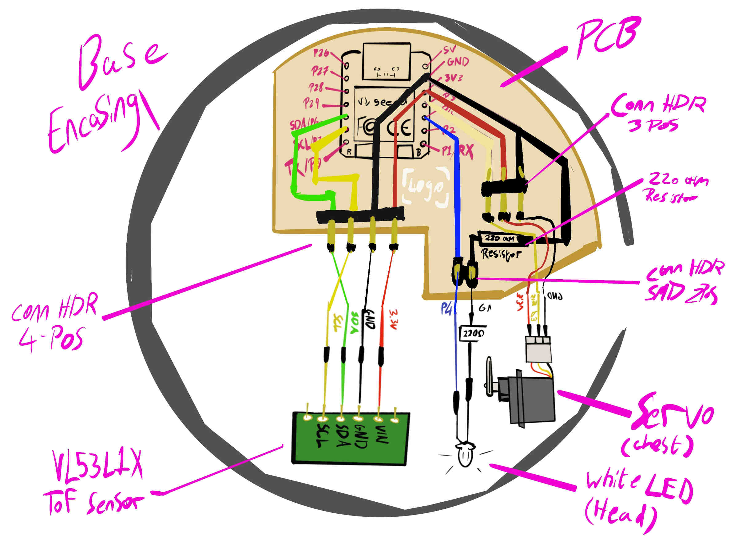
Now that the concept for System Integration is done, all I need to do now is design the board in KiCAD then fabricate it.
____________
Conclusion / Reflection
I agree with Neil that a week should be dedicated to System Integration as it was one of the processes that nerved me the most. I believe I was on the correct path, though I wish I could have done more. I wasn’t able to properly test my model or the fittings until after it was done printing which was the Tuesday afternoon, a day before the System Integration Week ends, with my high poly, full sized prototype unable to be finished until our actual Wednesday meeting, the day after I usually upload everything onto my website. So although things went smoothly this week, with a lot of good progress made, there wasn’t enough time for me to fully test out my fabricated designs - both PCB and Model. I can blame myself for not having the PCB fabricated before Wednesday's meeting as my nerves were very high. I didn’t want to design my PCB in KiCAD until I knew the Arduino/Breadboard was fully functional, and I stalled on testing it in case it didn’t work and I was stuck problem solving for the rest of the week. I was also conscious of giving myself too much documentation to cover in time for our Wednesday meeting. However I was very nervous about hollowing out my 3D model, adding fixtures and creating a PCB design because I’ve had multiple occasions where my designs ran into complications and was nervous I’d be stuck on the same complications - once again feeling out of my depth in Fab Academy. But as you can see from the above documentation, I managed to get through it. Of course, not everything worked out perfectly, and I will need to make a few changes, but in general I’m very happy with my progress this week and am well on my way to completing my Final Project and off to Mexico for Graduation (and a well deserved rest).____________