Group Assignment
Group Assignment Link:
____________
Some Early Safety Procedure Notes:
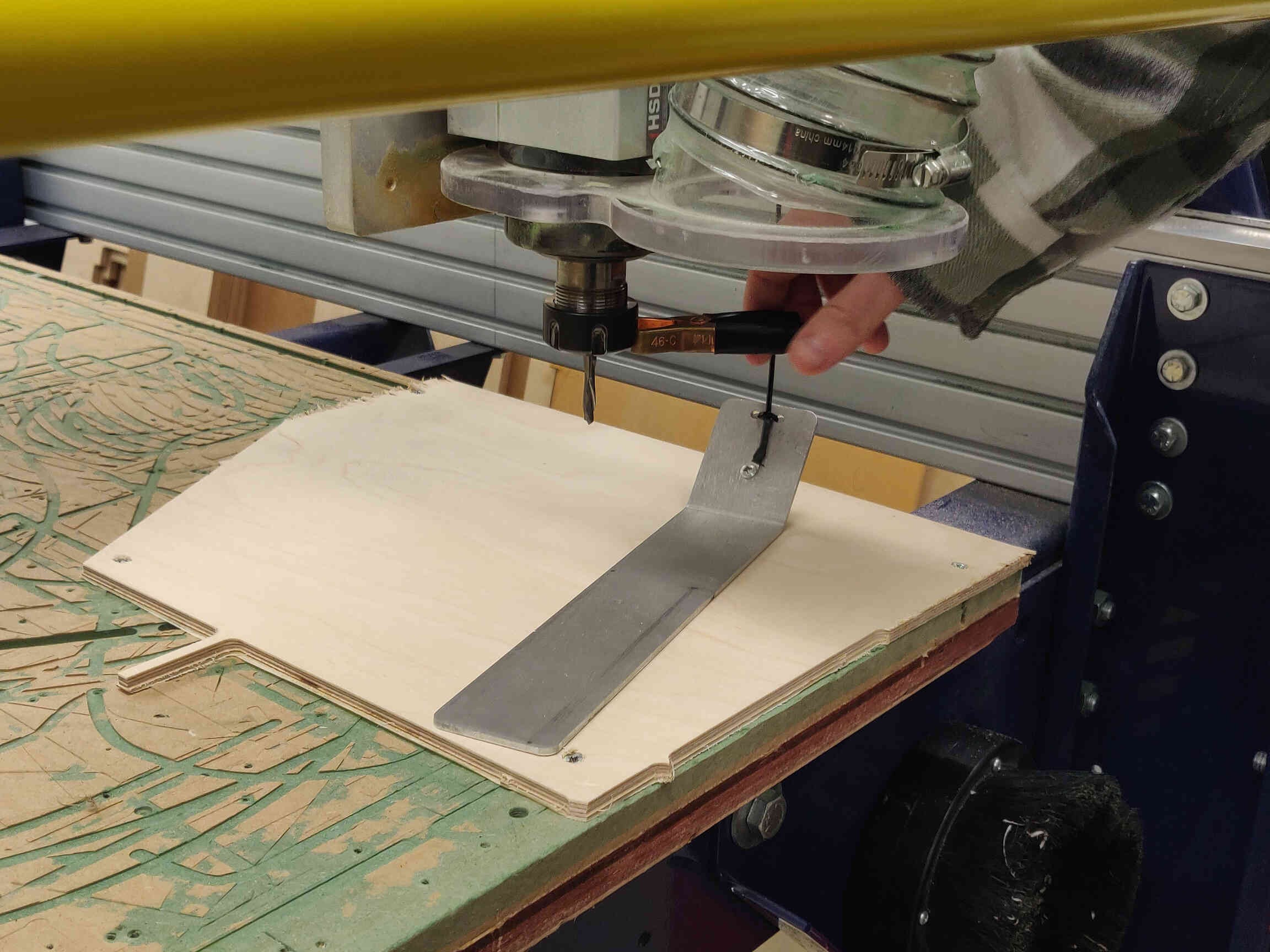
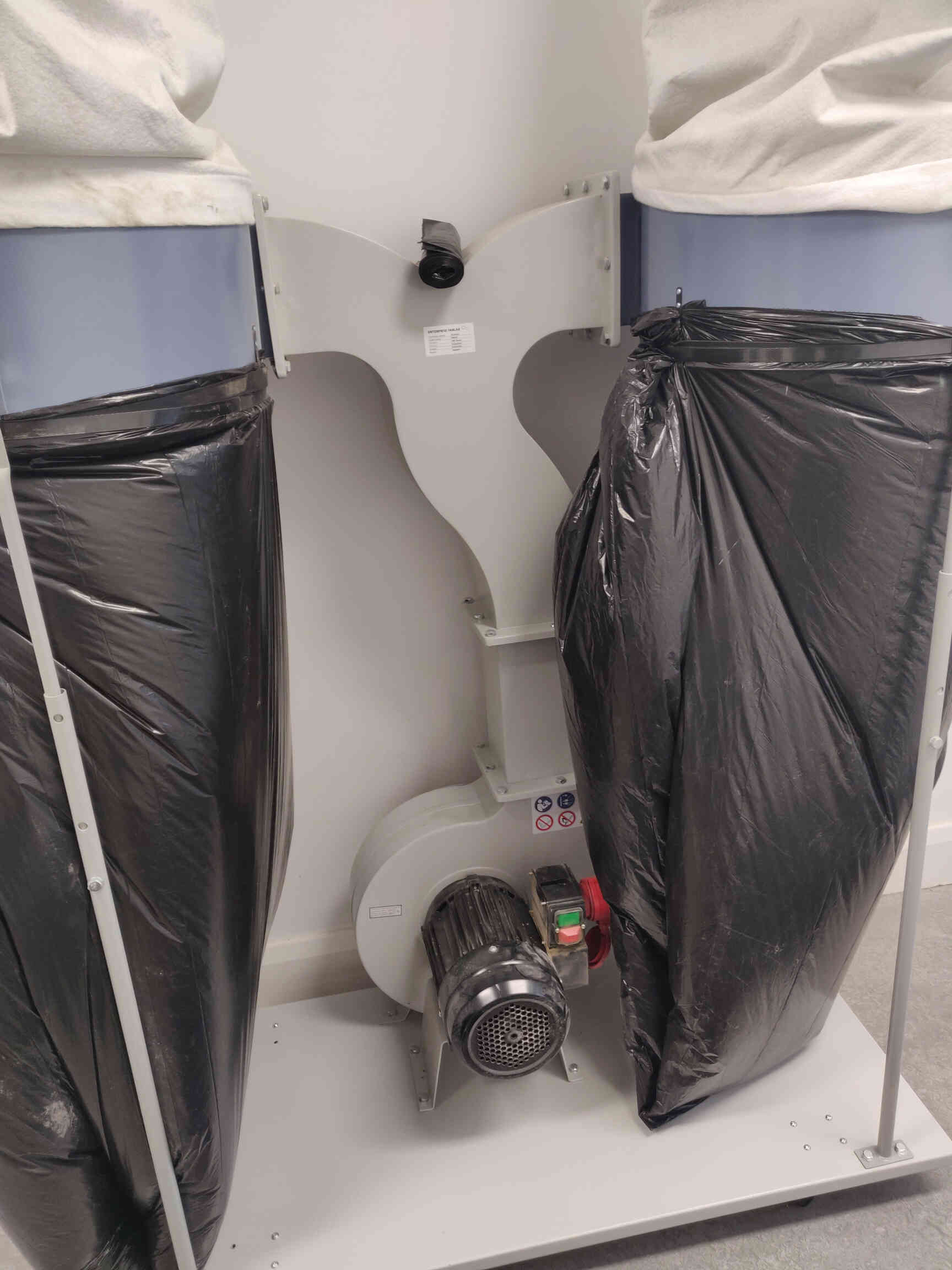
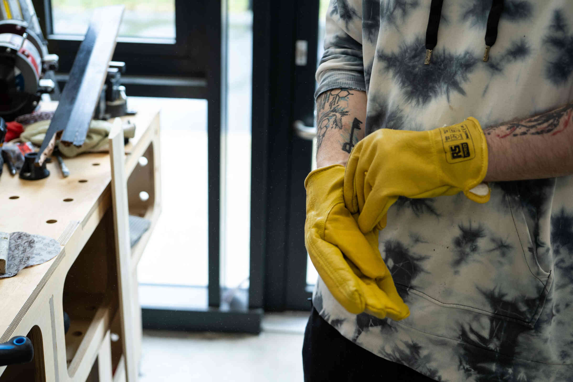
Don't touch sides - finger catching risk. When you interact with a CNC machine (changing tools), always turn it off first. Look, Listen & Smell. Possible Outcomes for not following Safety Procedures: Splinters, cuts, burns, impact, fires. Have tight gloves, not loose fitting. Use ear protection & eye protection. Wear a mask for MDF cuts for buildup of dust. Heavy boots in case something heavy falls. Using a blunt / dull drill bit can cause fires. It’s important to know how to stop the machine. Be aware of your personal & mental state when operating.Extra Notes: Why use CNC? Doing the work from the CAD side, then CNC used for repeatable projects, great accuracy. Can be used for many types of materials. (Wood, MDF, plastics, foams and aluminum.)
Designing, ShopBot Safety and Testing
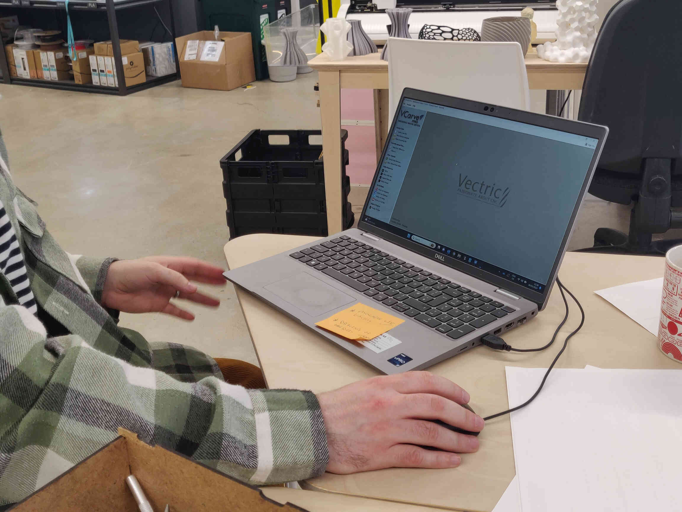
Our fablab technician 'Carl' gave me a full guided tour of milling something through a ShopBot that included the full process from start to finish.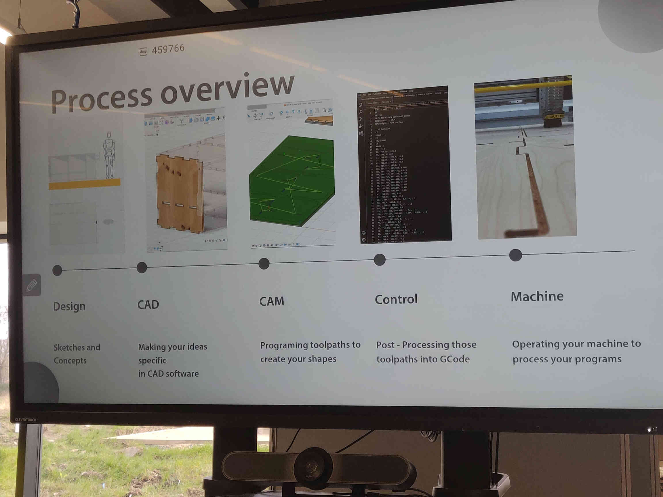
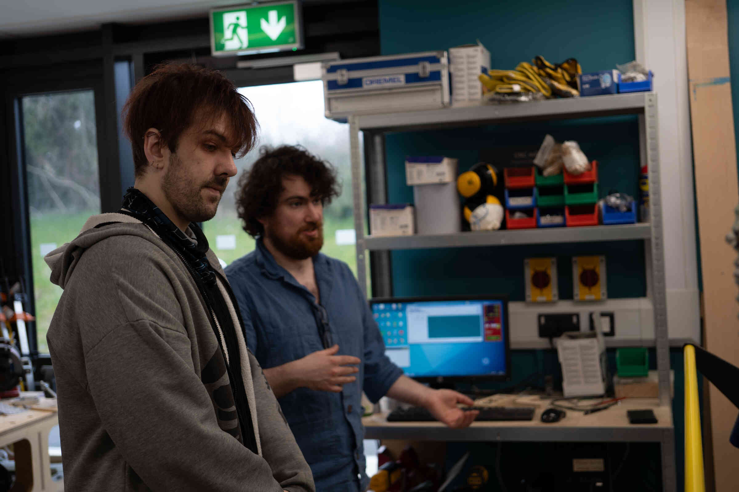
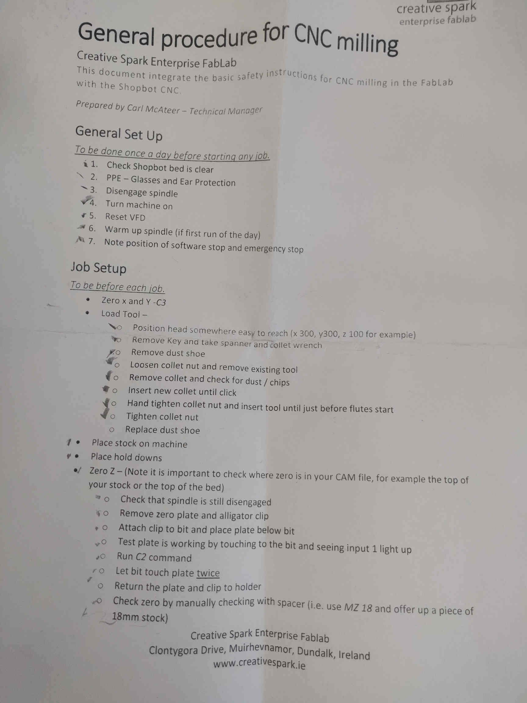
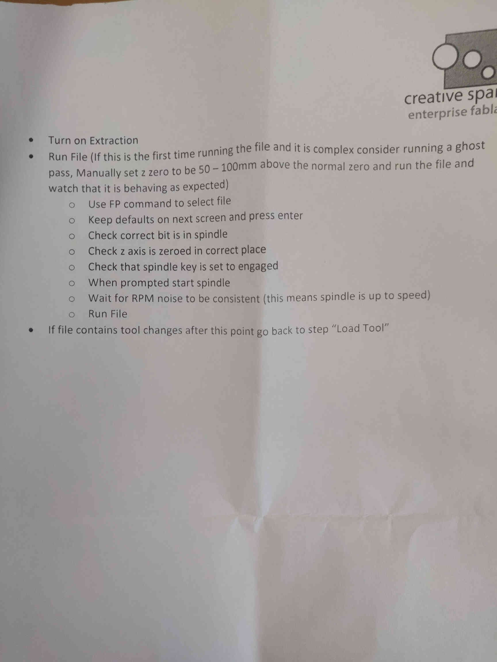
He guided me through the ShopBot machine process and all it’s safety procedures listed in this document:
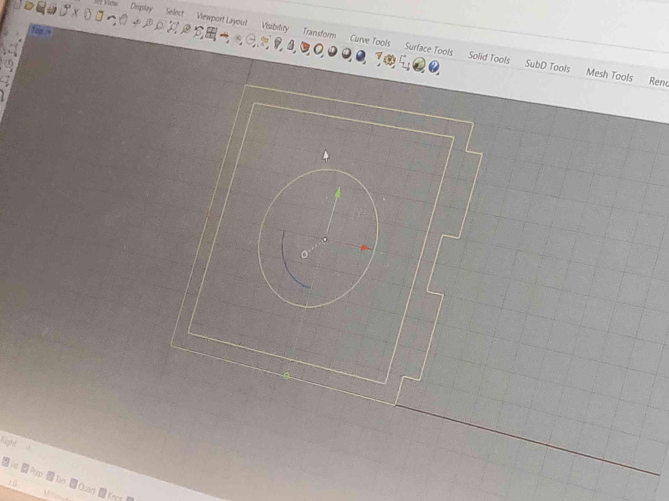
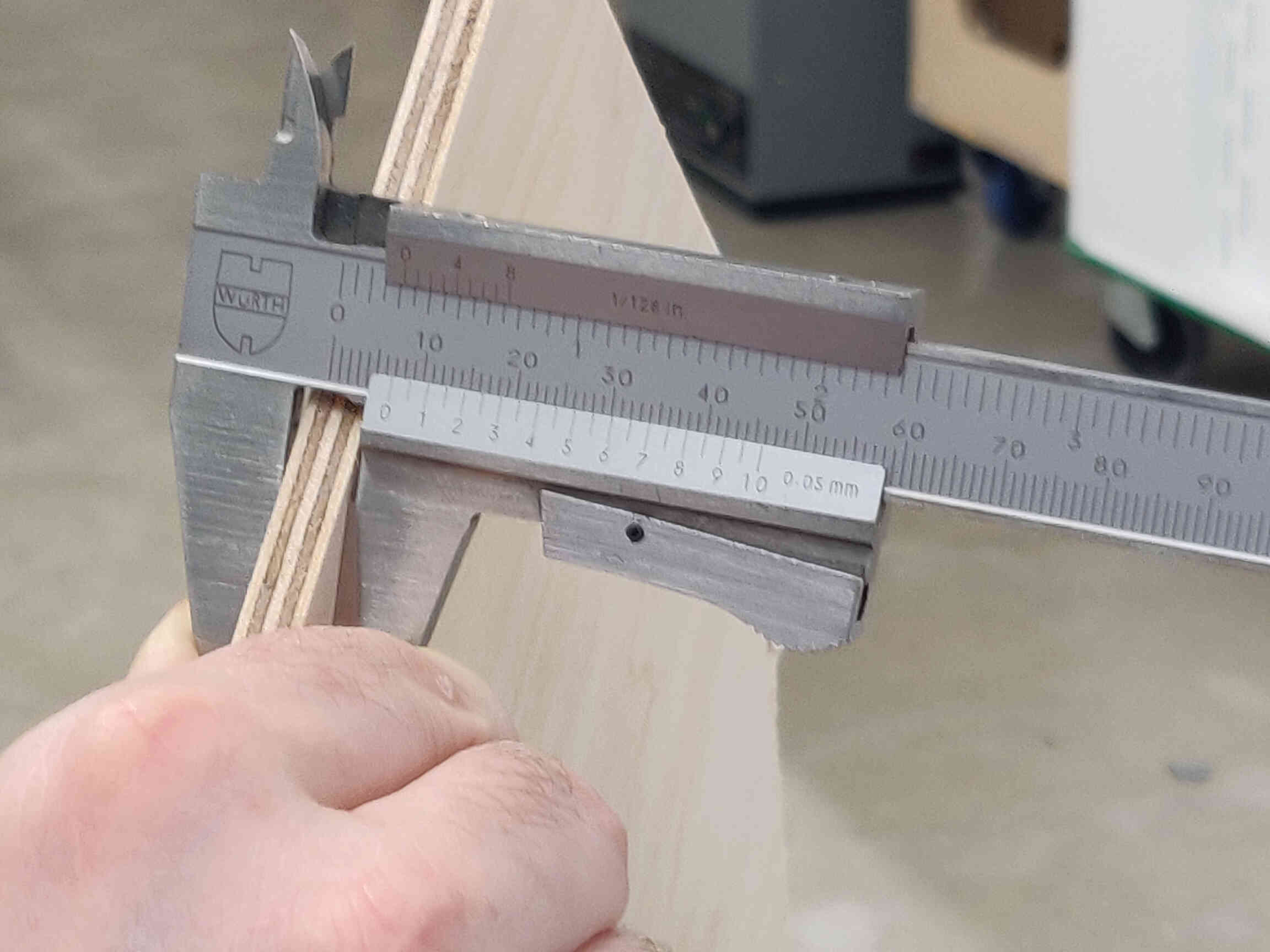
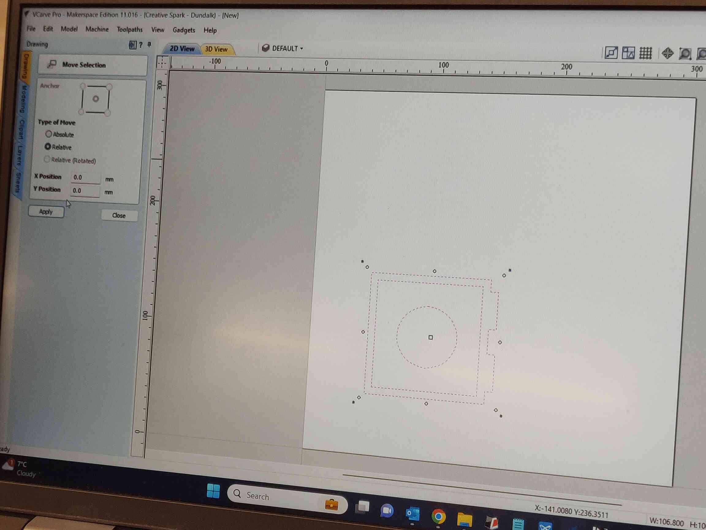
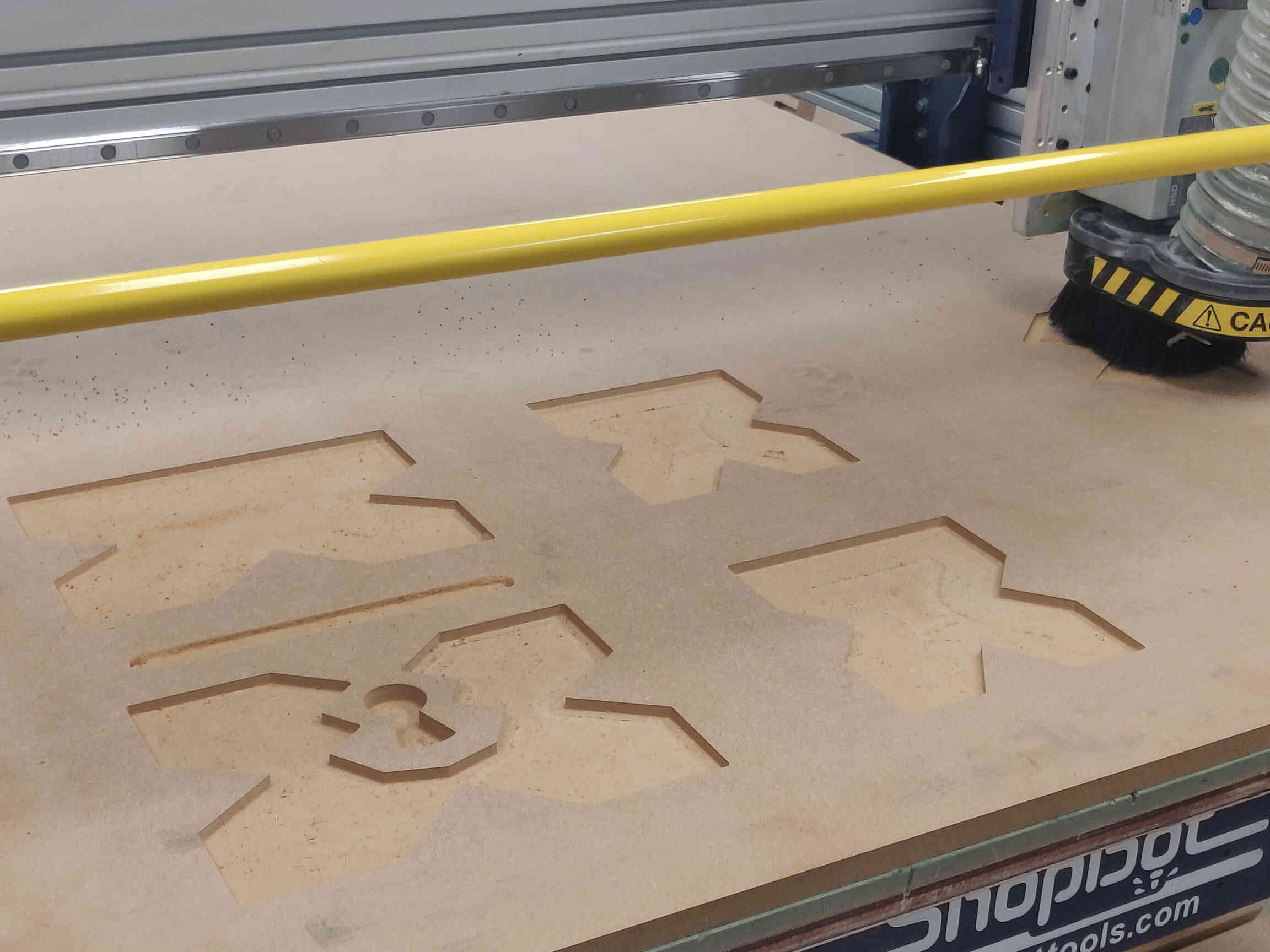
We started with a super simple design such as a square ashtray made from 6.8mm MDF. We made it with 2 simple squares appropriately distanced, then I added a circle in the middle and 2 joints at the edge - just to try adding some basic joints. We exported the design files as a DFX and brought it into VCarve. Here we went through the necessary settings and tools such as Profile and Pocket cuts. We exported them into 3 different g-code files, each being a separate milling process and named in order of job.

Once we finished exporting our CNC files, we went through and performed the full safety procedures for the ShopBot milling machine from start to finish twice over.
I was intimidated at first but was remarkably surprised how easy and understandable the process was - even when we had to edit the final g-code file as the outer line cut didn’t go the full way through. But as my instructors and technicians said, I can’t become complacent with the milling process, as a very simple mistake can easily cause machine or structural damage, fires, injuries, lost limbs and/or death.
It’s a highly dangerous machine and you must be entirely vigilant of your surroundings, mental and physical state and of your equipment - something as simple as a dull endmill or a tired operator could prove catastrophic.
In the end, everything went smoothly during our introductory run and I left with an ash tray that I designed and milled myself. Starting next week I’ll be able to mill my very own cartoon treasure chest!
____________
Individual Assignment
____________
Wednesday Meeting
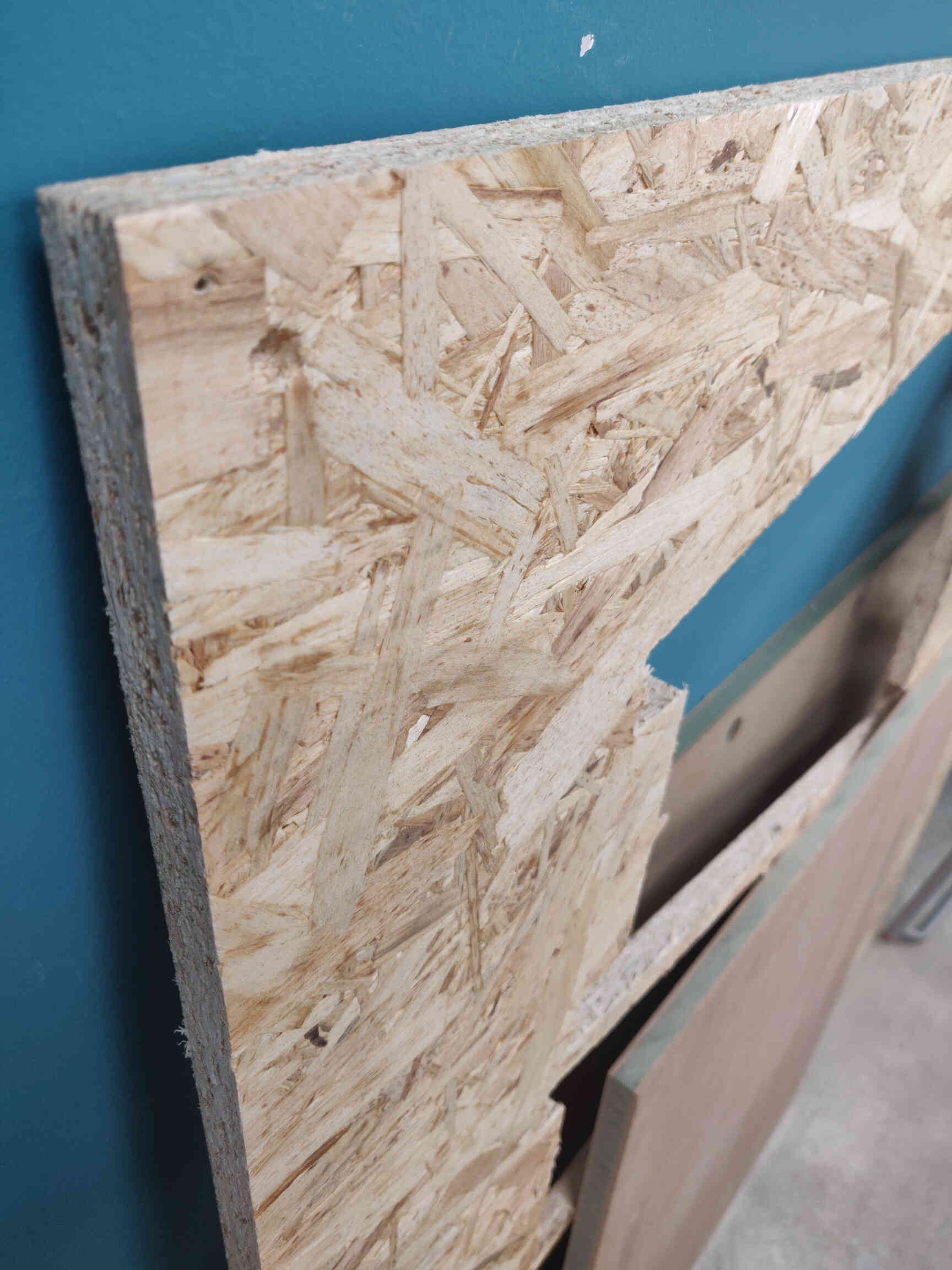
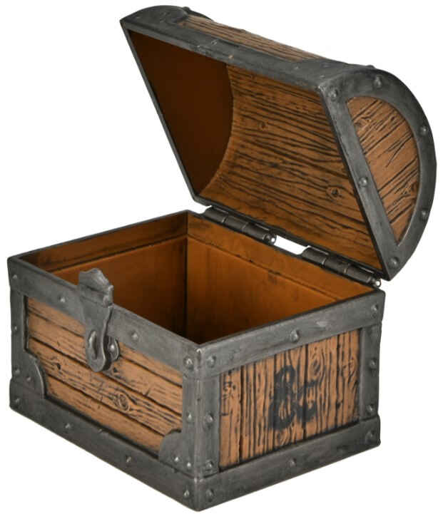
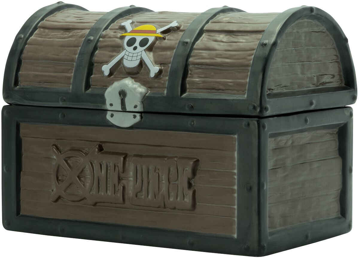
We’re gonna be making something BIG for this assignment with large scale machining using ShopBot - a classic milling machine for this week. The main material we will be focusing on using will be wood.Examples of Wood Material for cutting:
____________
CNC = Computer Numerical Control.
CNC Router specifically - large machine mainly used for cutting wood. CNC Tooling used for prototyping and full production for cutting, carving, machining and milling.Feeds = Speed at which it cuts a material path.
Toolpath = The information the machine uses to direct the drill bit through the material. Toolpaths operate as vectors.
Pros: Versatile, low tooling costs
Cons: Speed is limited by quality. Limited by 3-axis - can’t milling underneath material.
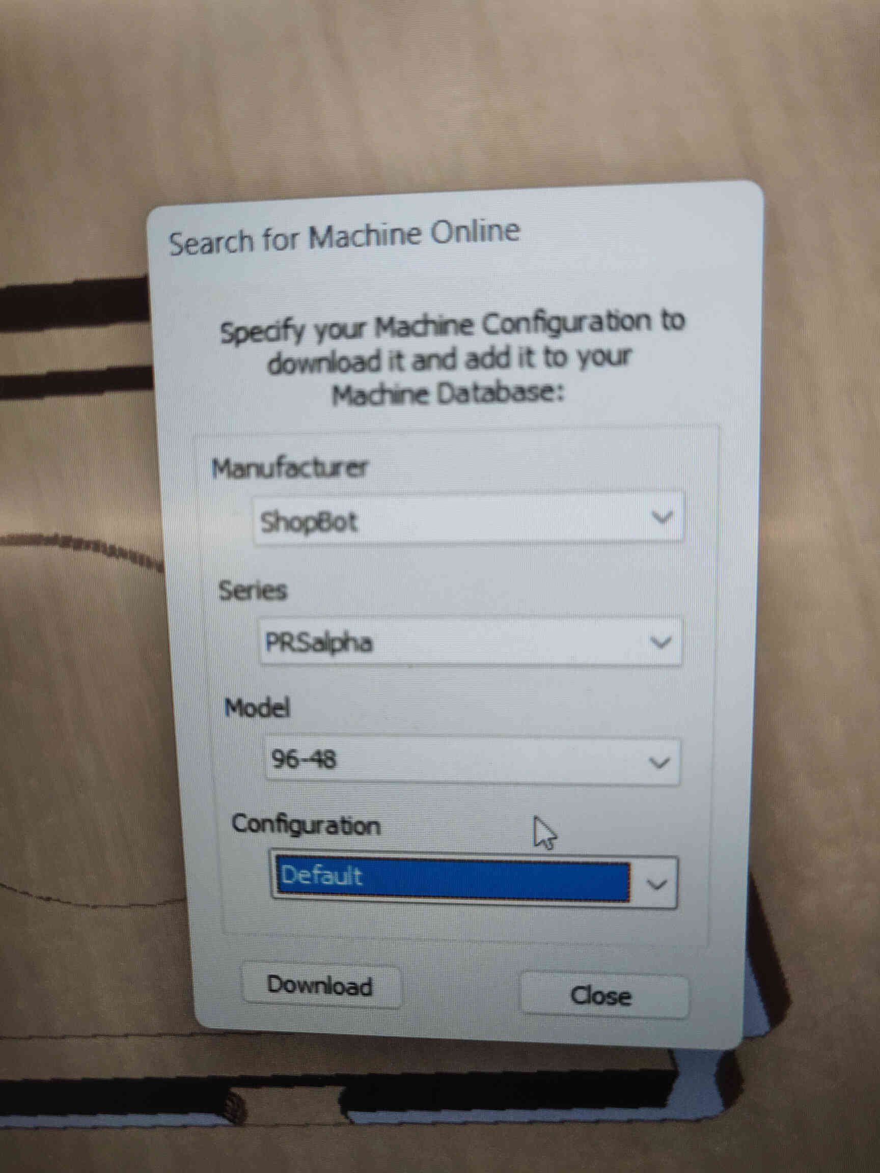
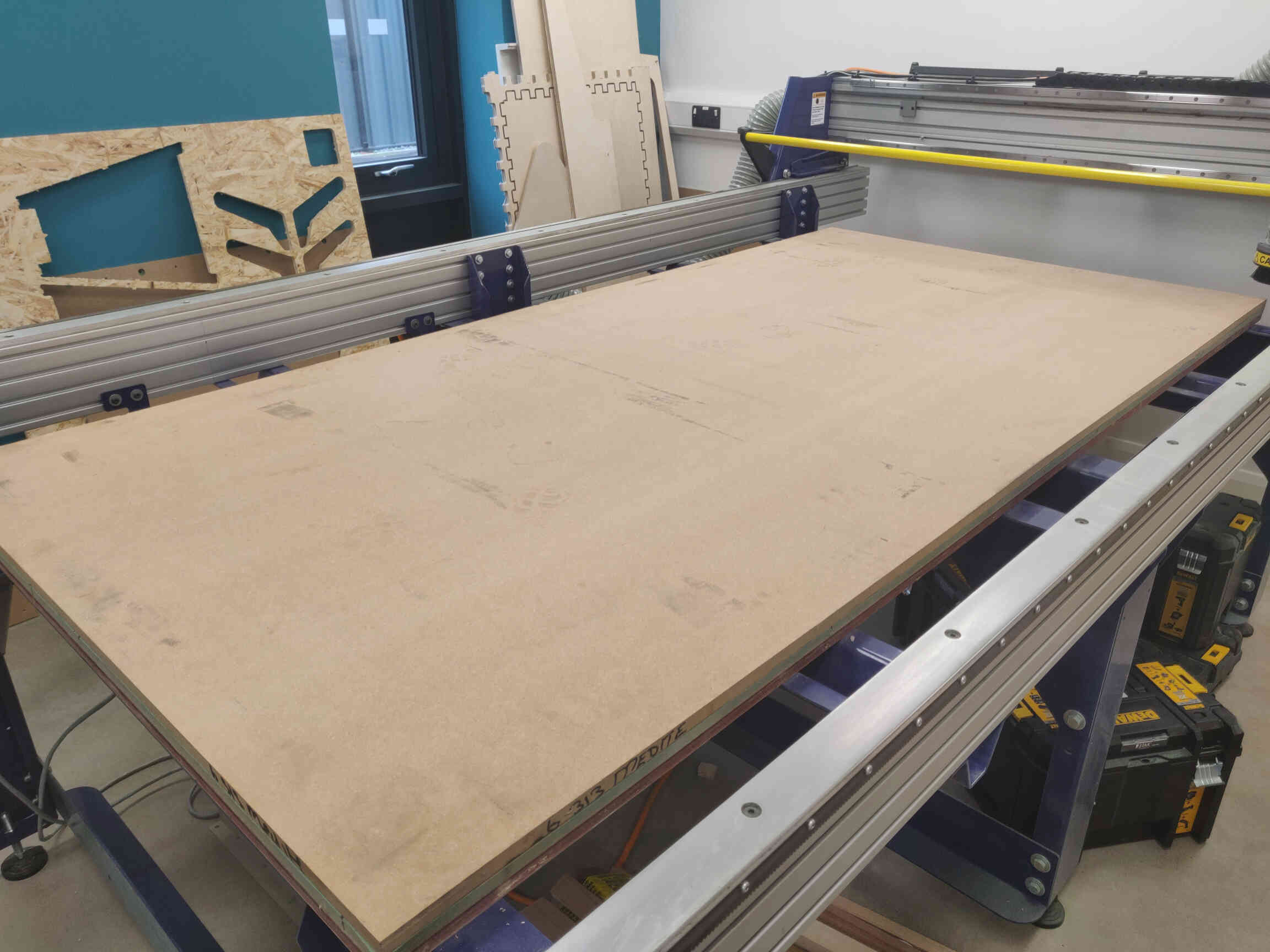
Our CNC machine: ‘ShopBot PRSalpha’.
Cut Movement Area: X - 2440mm Y-1220 Z- around 150
Process: Design -> CAD -> CAM -> Control -> Machine.
You are limited by your toolpath - keep attention to variables like flute length for deep cuts.


Software CAD: Rhino & Fusion 360____________
Software & Machines
Software CAM: VCarvePro
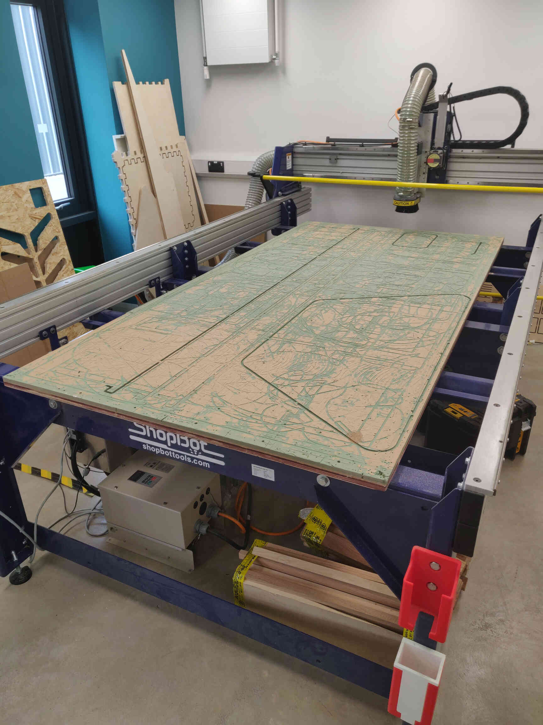
CNC Machine: ShopBot
Toolpaths: Drill, Pockets, Profile/Cutting, Engrave, Counter.
Tooling: Drill, Endmill, Ballnose / Tapered Mill - Chamfer Mill / V-Bit Mill, Face Mill / Mortising Bit.
If machine is squeaking - speed is too low.
“If the machine screaming, it’s looking for work.”

Discussed concepts with my instructor and local technician. We talked through various options for the process including design complications, software & machines I plan to use and joint designs. My initial plans were to use Fusion 360 to create a 3D design which would then be milled using the ShopBot machine.
However after weighing the options and guided through how this type of milling process goes, I ultimately decided that I would use the website MakerCase to create and download a box template, which I would then import as an SVG of DXF into Rhino software to make 2D parametric designs. Then bring those designs into VCarve to convert into g-code and send to the ShopBot machine to mill.
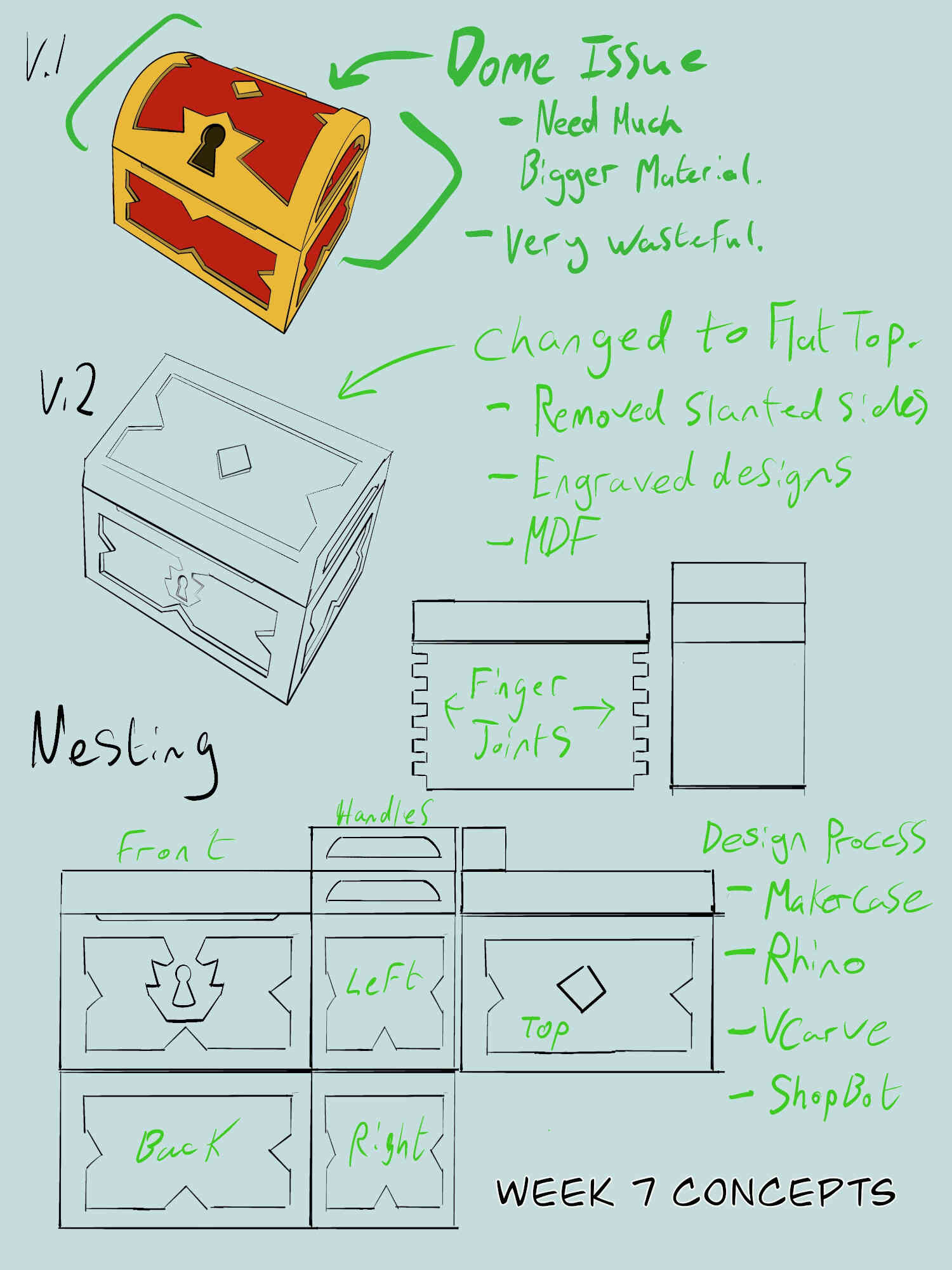
So I settled on a flat top for the chest with updated engraving designs. I also considered creating the box as a base using MDF, then would cut out the extensions made from OSB and join/fasten them on. After seeing how ‘Pocketing’ is done in VCarve, I decided to have the engravings as part of the MDF Base - meaning less material needed or wasted, less weight and more likely to get extra credit for “no fastenings or glue”. The sides are also no longer slanted and we are going with finger-joints. It was suggested by my instructor that I should make and download a box template from the MakerCase website, so we can update the design from there.
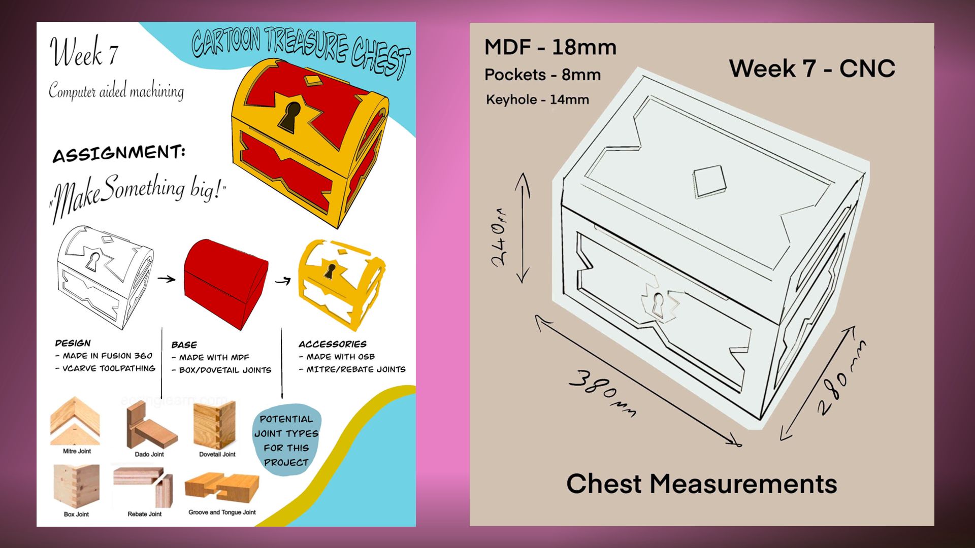
Width = 380mm | Height = 280mm | Depth = 260mm.

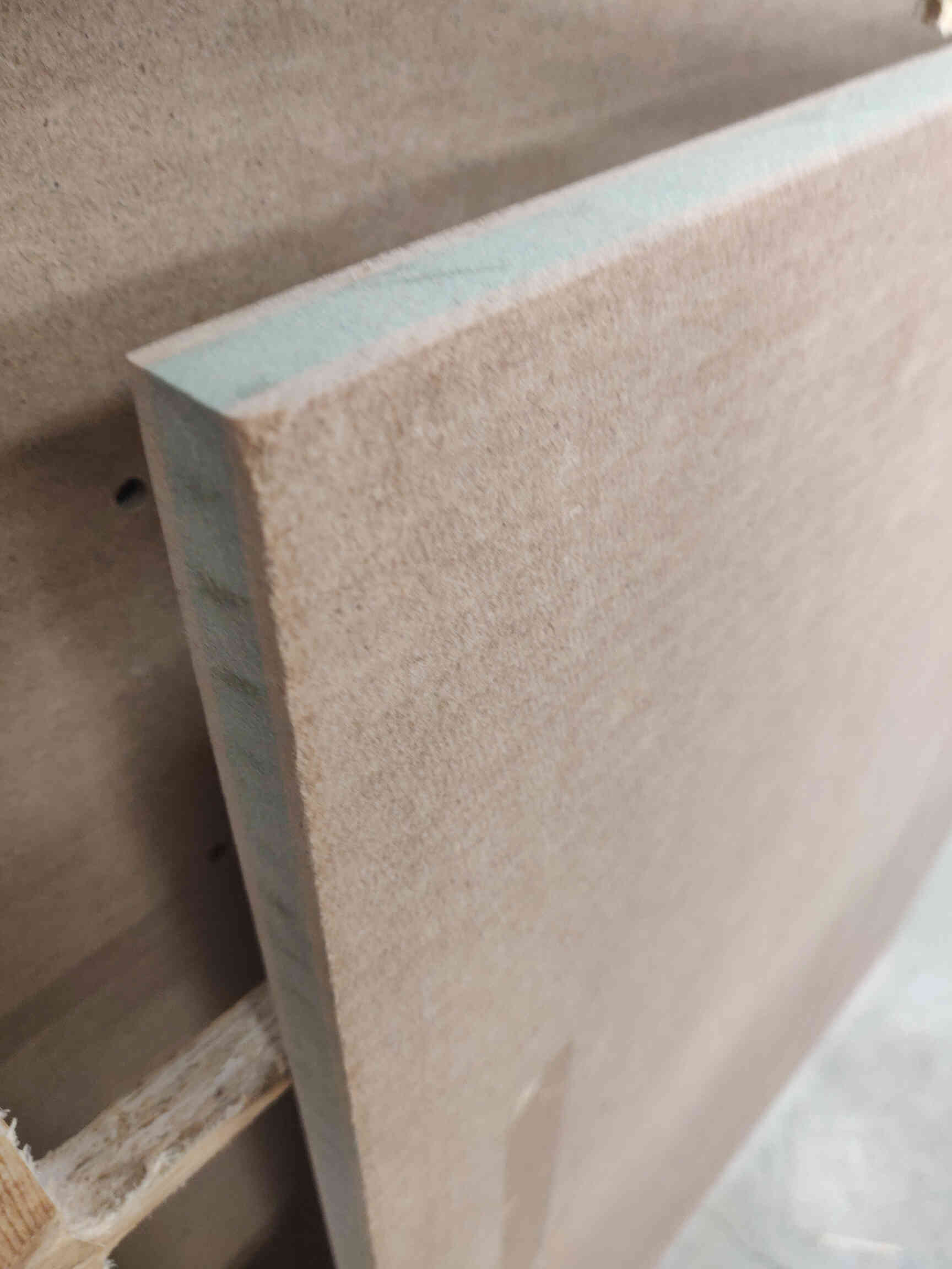
The dimensions were set to the OUTSIDE. Material Thickness of MDF is 18mm.
Originally I set it to be a ‘closed’ box, but I didn’t want the top of the chest to have finger-joints as I felt it takes away from the Treasure Chest look, so I set it to OPEN - choosing to design the top myself so that it will sit on top of the box can can be opened with a hinge later on.
Set Edge Joints to ‘finger’ and Finger Size to 36.
Afterwards I downloaded both the SVG & DXF files, though the intention was to bring the DXF file into Rhino3D.

After bringing the template into Rhino, I set about making my design. Against my own wishes to design the chest with a lot of detail, I chose to keep it super simple as I don’t have a lot of time in the Fablab to operate the ShopBot mill and I didn’t want to put myself under pressure if things go wrong.
For designing in Rhino, we are mainly going to stick to these design tools:
Polyline, Rectangle, Circle from Point and Arc tools.
Also to edit our designs we can use the commands:
Join, Explode and Trim.
Rhino, similar to Adobe InDesign, is fantastic at measuring space, midpoints & distance. A great way to get a concise design is to create lines that act as borders or guides, allowing you to correctly gauge spacing when making your design. Utilizing this user-friendly performance, we can use the simple tools listed above to accurately shape our design.

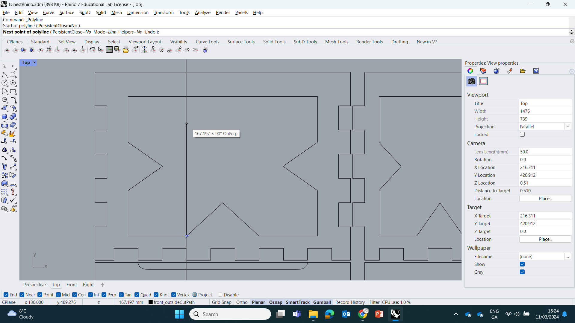
Now we will make a Rectangle Border that goes on the inside of our Front Panel design with 20mm spacing on either side. To measure this, I used the Polyline tool to draw a 20mm line on each side, then starting at the top left corner, I used the Rectangle tool to create a rectangle that's the same height & width as the Front panel. Then I clicked on the newly made rectangle, then used the scale options (little square boxes on the RGB Gumball) to scale it down so that each side connects to the 20mm lines we created earlier. When that's done, you're free to delete the 20mm guides (lines we made).
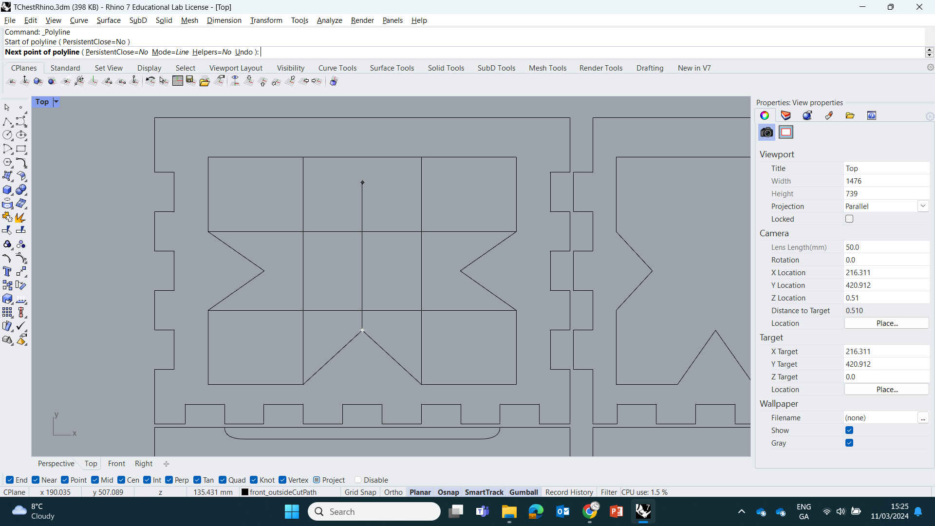
Now select the Polyline tool and find the midpoint of the left & top side of your rectangle, then draw a line going across each midpoint to form a cross intersection. With that done, draw another line going straight across around 20mm above that horizontal line. Select the new horizontal line and in the command menu, type and select “Mirror”. Now click on the middle horizontal line - this will give your Mirror command a reference for where the midpoint is located and how far spaced the mirrored design will be. Then you need to angle the mirror (using your mouse) to place it correctly. Make the mirror line be 20mm BELOW the middle horizontal line.
Now we have our guides, we can start making the pointed arrows on the left, right and bottom of the inner rectangle. Do this by selecting the Polyline tool and simply draw two lines forming the arrow using our guides as a measurement reference.


(Creating Keyhole Design ^)
Now that we have our lines down, we can Delete or use the ‘Trim’ command to delete the reference guides & inner arrow lines - this can be easier with the Explode & Trim commands - allowing you to delete jointed sections of your design. The ‘Explode’ command is basically the opposite of the ‘Join’ command. Exploding your design will separate all the connected line joints into individual shapes, making it easier to remove unwanted lines. When finished, Drag Select your inner design then type & enter the ‘Join’ Command to join all all the lines into one shape.


(Creating Keyhole Design ^)
Note: If any lines are still disconnected, then there might be a open space hidden between you joints. Find the parts that aren't connecting, then zoom in really close with the mouse wheel until you see the gap. Then use you mouse/selection tool to click and Drag the lines into place. Then zoom back out, select all the lines you wish to connect, then enter the ‘Join’ command again.


(Creating Keyhole Design ^)
Copy & Paste your inner engraving designs from earlier and add one to the new “top” panel.
We will make 2 simple additions to this inner design. Using the methods I detailed above, add an arrow to the top line pointing inwards like the others. Then add a diamond shape directly into the middle using the rectangle or Polyline tool.
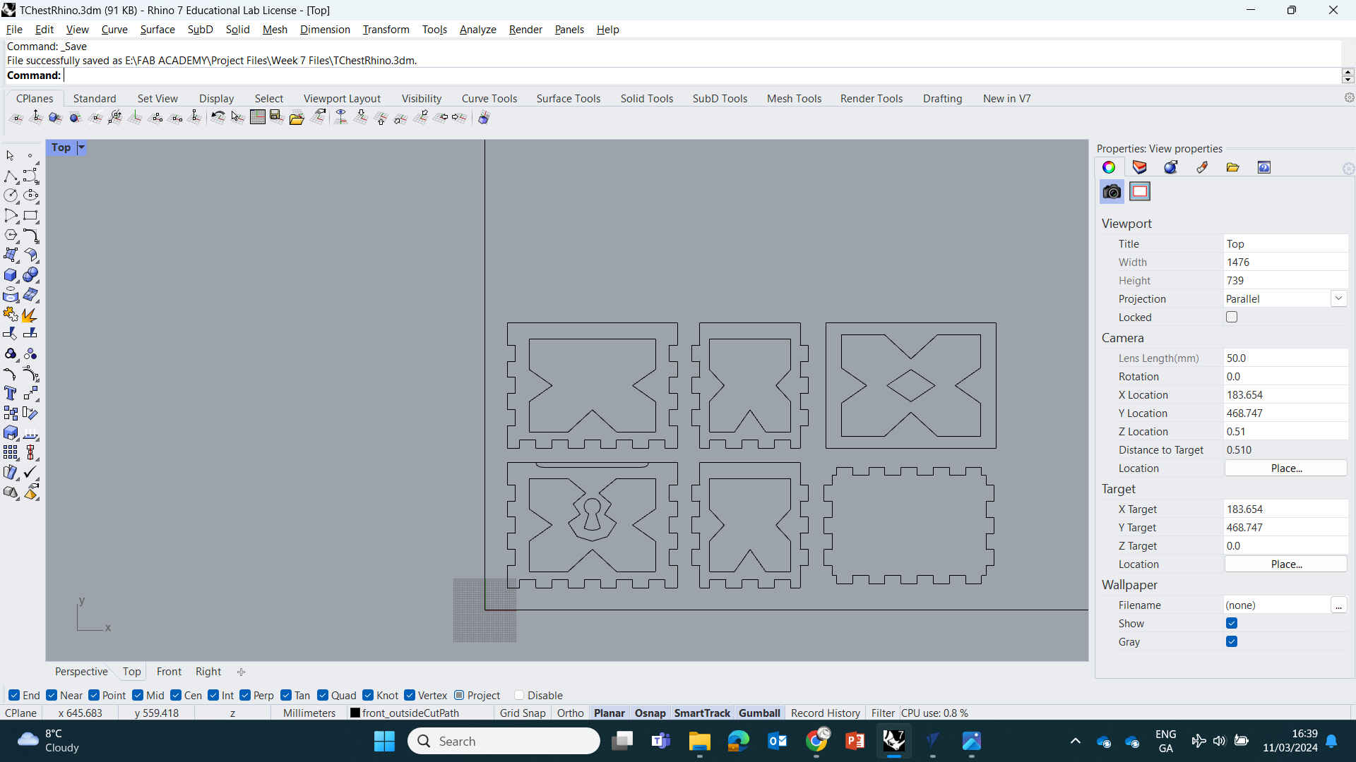
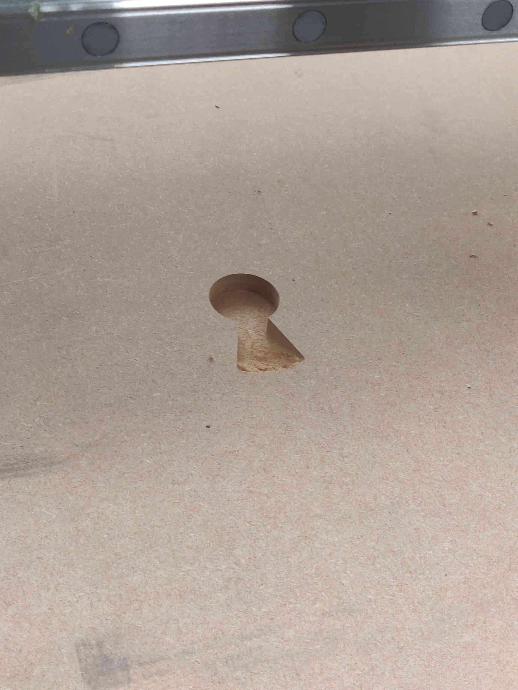
Using the tools and methods as detailed above, I created the Keyhole, Front Finger holes, Orgaainzed designs for Nesting, then selected all and exported design as DXF.
Focus on first two toolpaths - Profile and Pocket.
Pass Depth - same as tool depth. Standard Spindle feed 12000rpm.
For Passes use Offset instead of Raster. + Conventional Milling.
Ramp Plunge Distance 50mm.
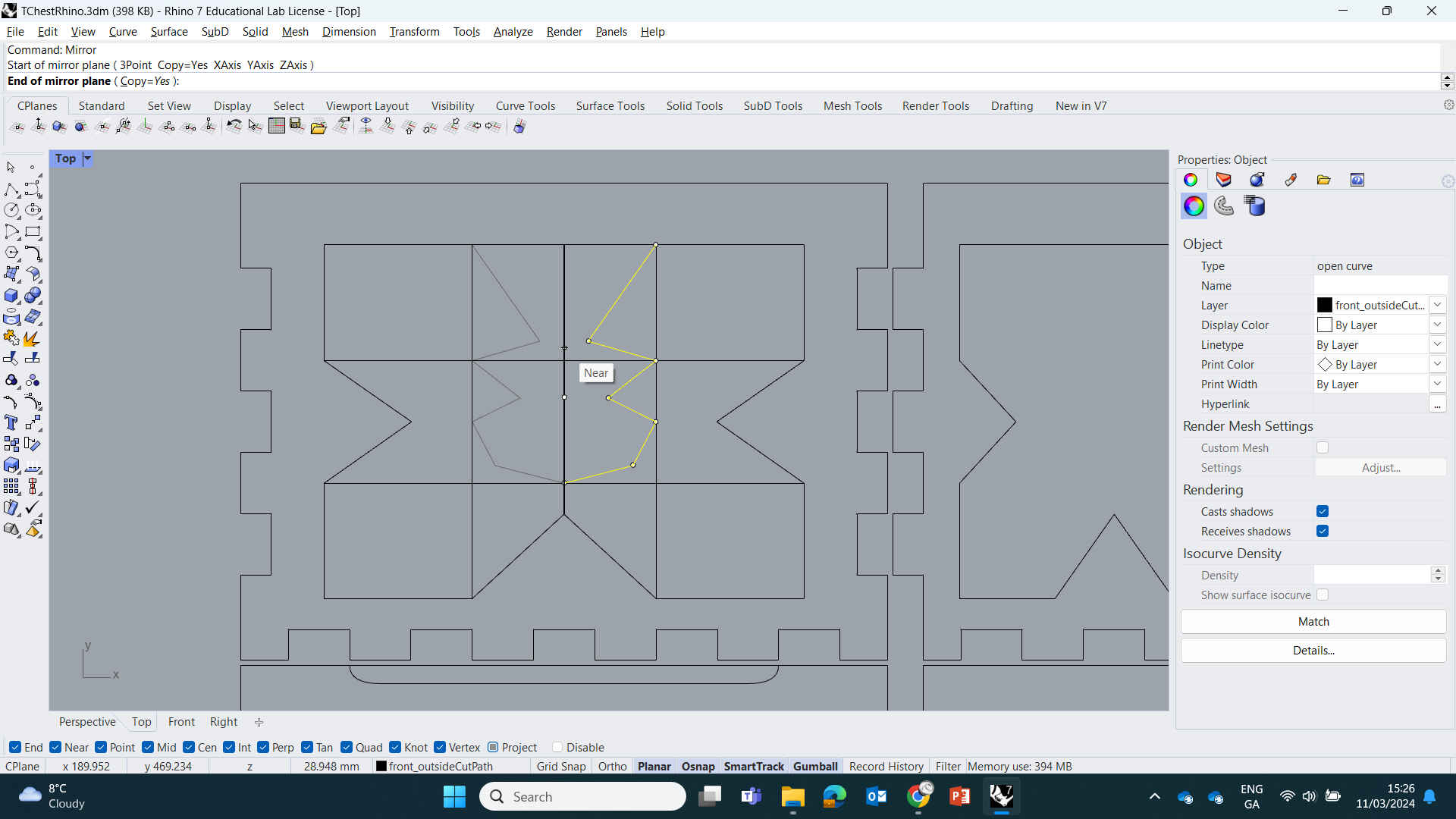
EDITOR’S NOTE: MakerCase added its own small dogbones into the design (yes it was my fault) and now it wouldn’t allow me to remove them to add proper-sized dogbones through VCarve. So I went back to the design files in Rhino to manually delete all the MakerCase dogbones and rejoin the broken links so that I could add the proper dogbones in through VCarve.
Once that issue was fixed, we selected the lines for creating ‘Pockets’ and ‘Profiles’ - then saved each file, labeling them correctly.
1 - Pocket - 6mm
2 - Pocket - 12mm
3 - Profile - 18mm

(Chip load = 0.1mm)
Spindle Speed: 18000rpm / Feed Rate: 3600mm/min / Plunge Rate: 1800mm/min /
Ramp Plunge Distance: 50mm / Cut Direction: Climb
Pocket Toolpath 2 (End Mill 6mm): Cut Depth 6mm / 2 Passes
(Chip load = 0.33mm)
Spindle Speed: 12000rpm / Feed Rate: 7800mm/min / Plunge Rate: 3900mm/min /
Ramp Plunge Distance: 50mm / Cut Direction: Conventional
Profile Toolpath (End Mill 6mm): Cut Depth 6mm / 3 Passes - leaving 0.5mm stock
(Chip load = 0.33mm)
Spindle Speed: 12000rpm / Feed Rate: 7800mm/min / Plunge Rate: 3900mm/min /
Ramp Plunge Distance: 50mm / Cut Direction: Climb
Finish Pass: Conventional Cut Direction - Removing the 0.5mm in one pass.
- Add tabs to toolpath: Length & Thickness: 10mm
- Machine Vectors: Outside / Right
Feeds & Speeds / Chip Load Calculator Excel
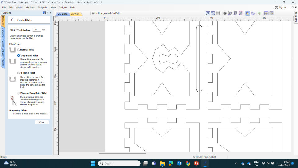
Dogbones: Dogbones are rounded notches that you add to any and all sharp corners, as it accounts for the size of the End Mill and it's inability to make a perfectly sharp corner. Adding dogbones within VCarve will create outer rounded corners that will allow for a much nicer and smoother fitting & assembly process. These can be added in VCarve by selecting Create Fillets -> Dog-Bone Fillet.

Editor's Note: I added dogbones automatically while making the box in Maker Case as the option was there. However they weren't the proper size that we needed so I needed to replace them with ones through VCarve instead. However, complications arose as VCare couldn't just 'replace' the dogbones - I needed to return to the Rhino DXF files and individually delete every single dogbone and reconnect the corners.
Let this be a lesson - I could have saved myself 2 hours of work and problem solving by just not selecting automatic dogbones within Maker Case.

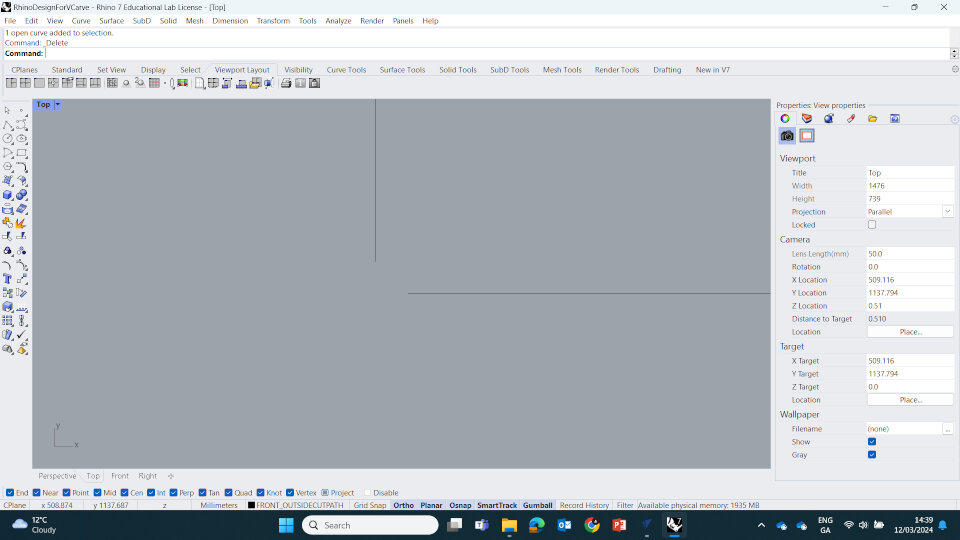
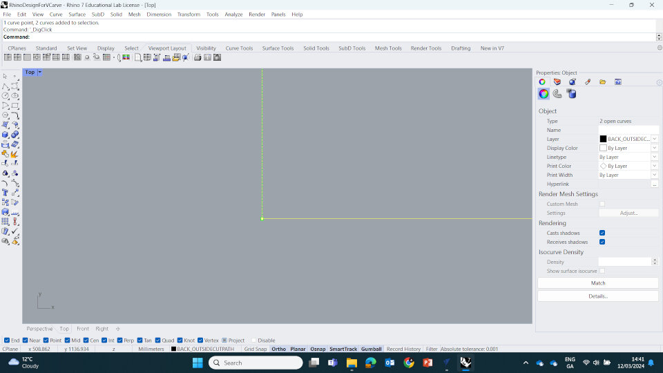
(Fixing automatic dogbones in Rhino ^)
We saved each cut as it's own toolpath files and organised them accordingly:
1-Pocket-12mm-KeyHole
2-Pocket-8mm-FaceDetail
3-Pocket-8mm-FaceInlay
4-Pocket-5mm-FaceHandle
5-Profile-18mm-Cutout
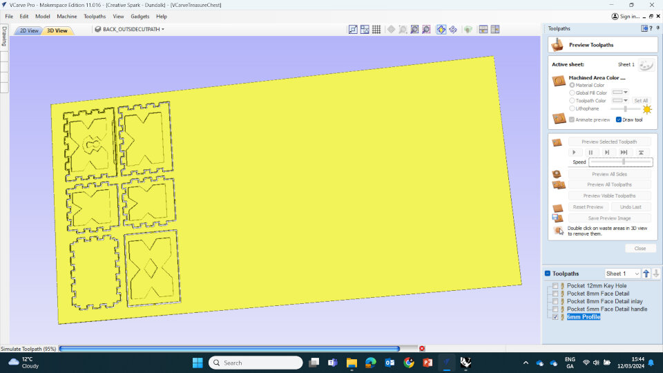
Then we viewed the toolpath simulator within VCarve. Once satisfied, we saved the files and brought them to the ShopBot Machine.
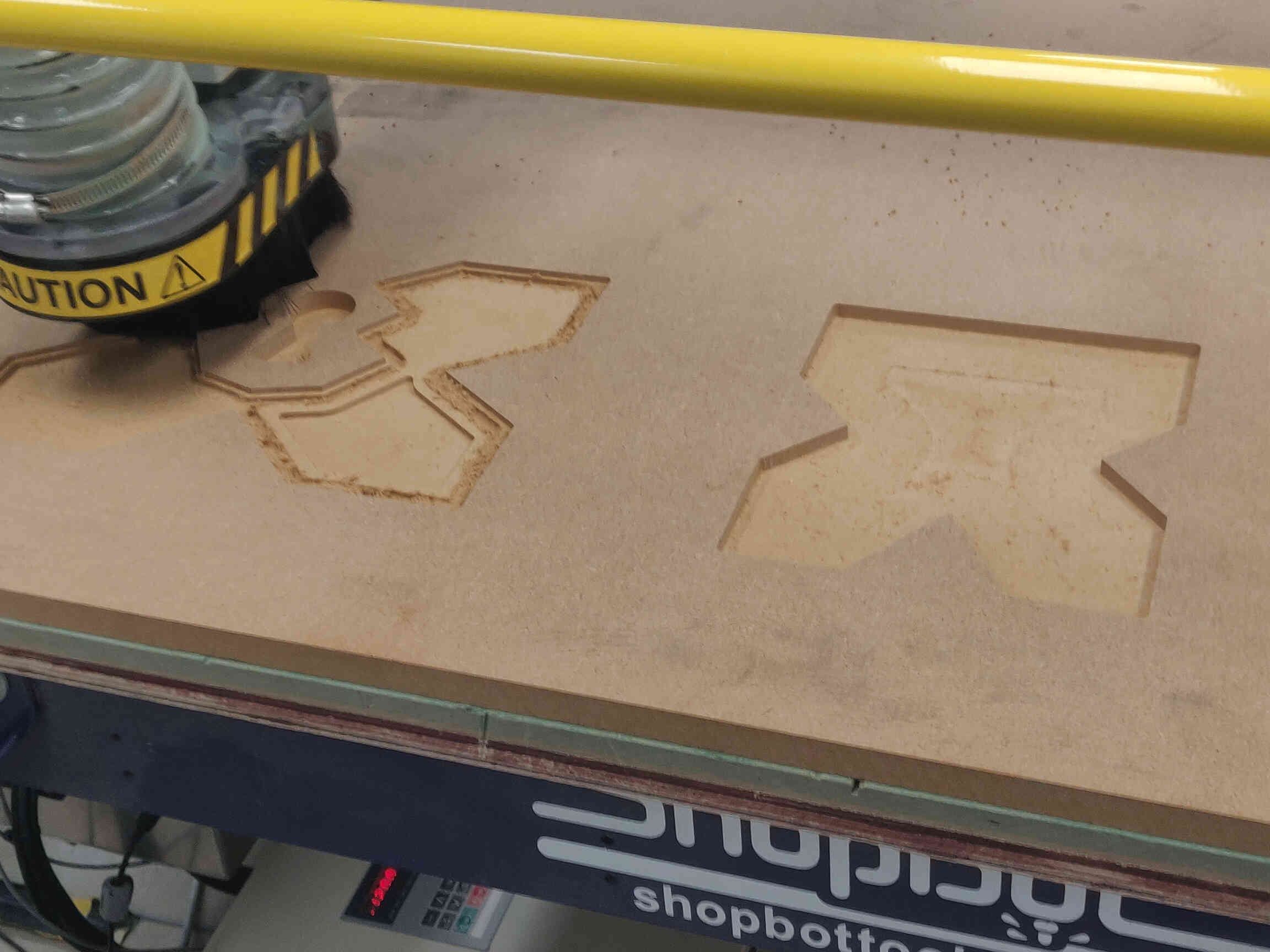
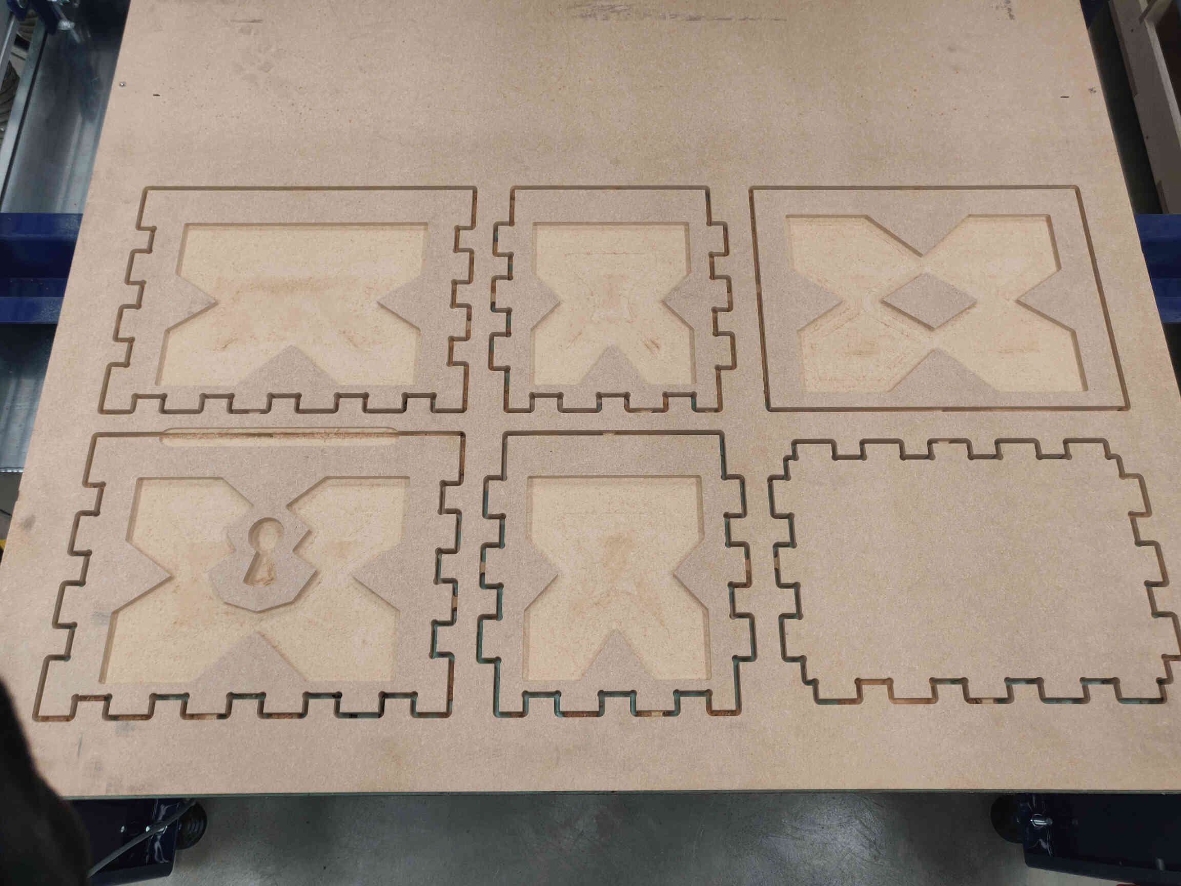
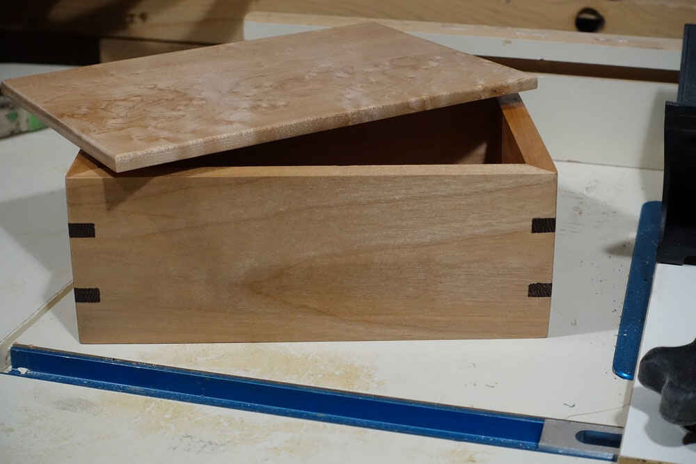
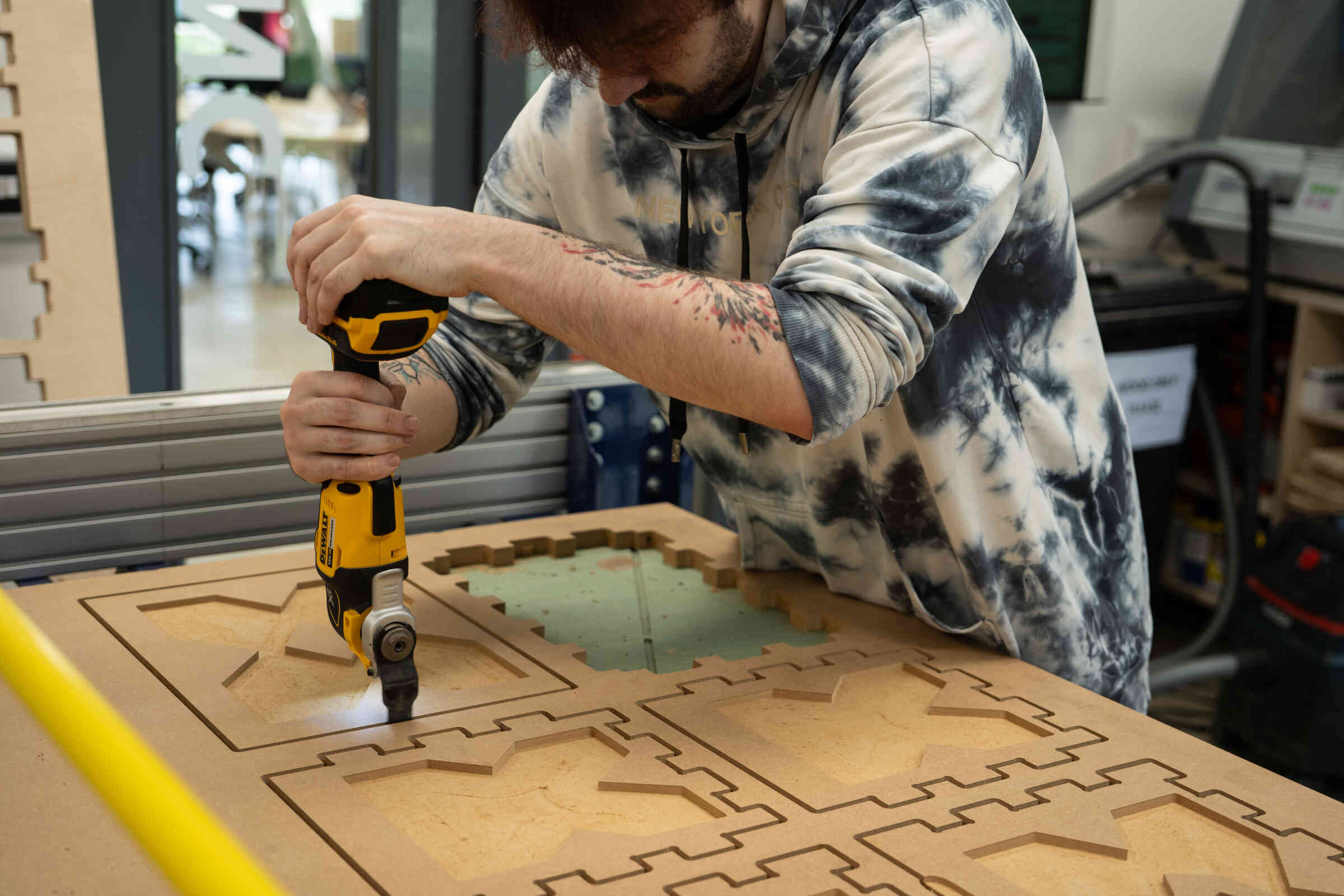
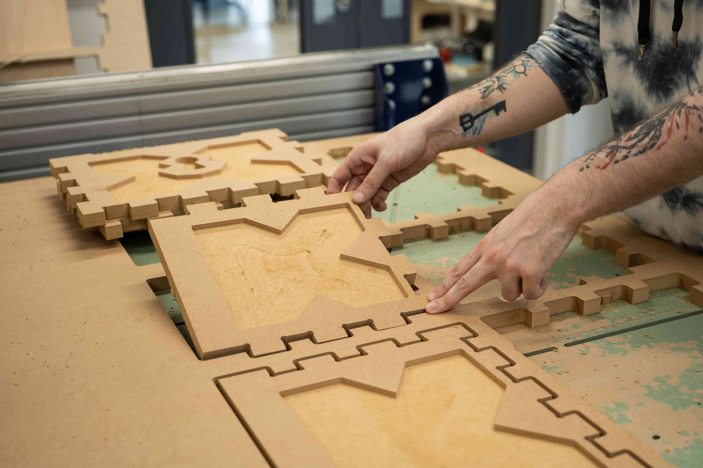
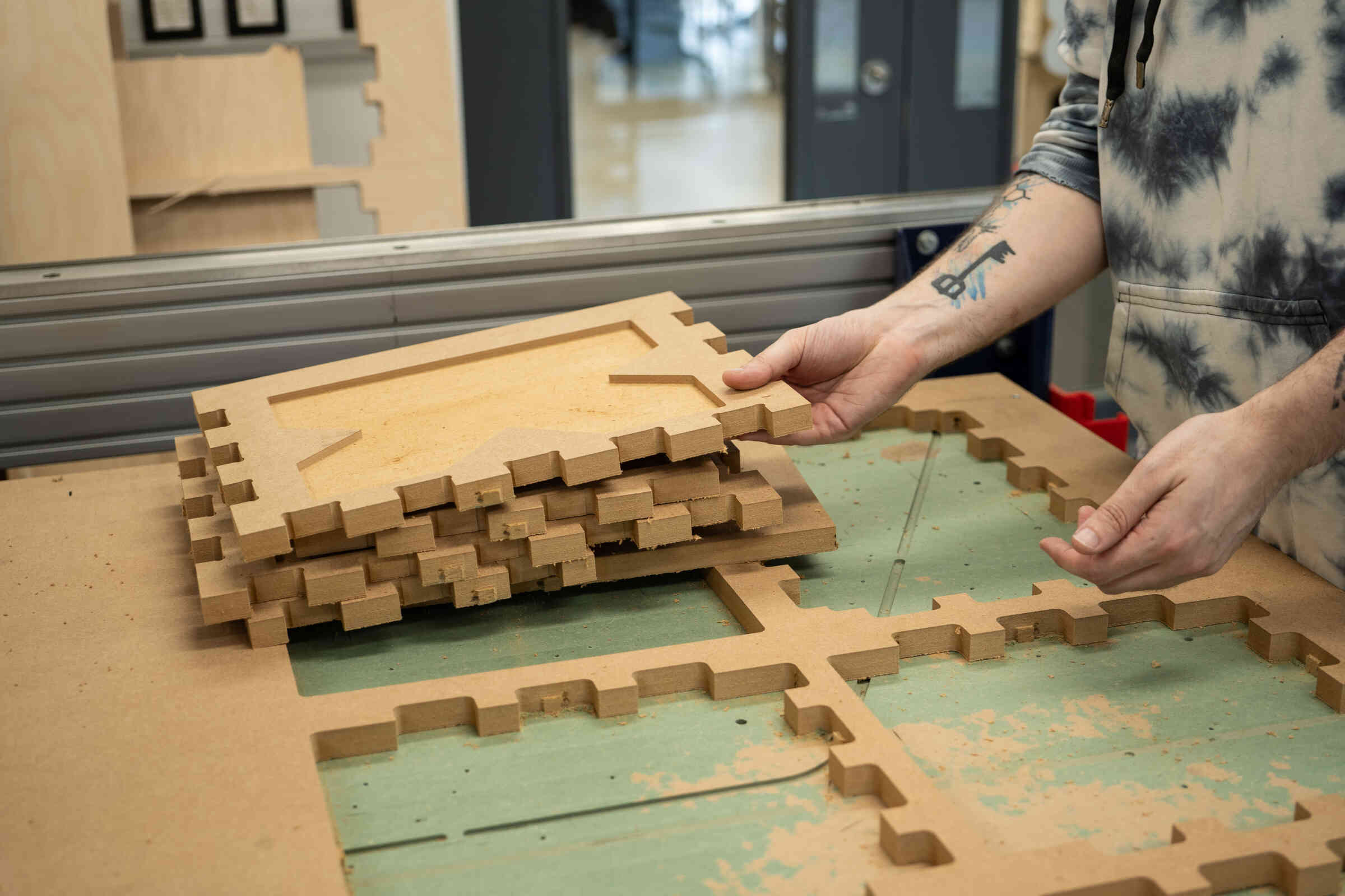
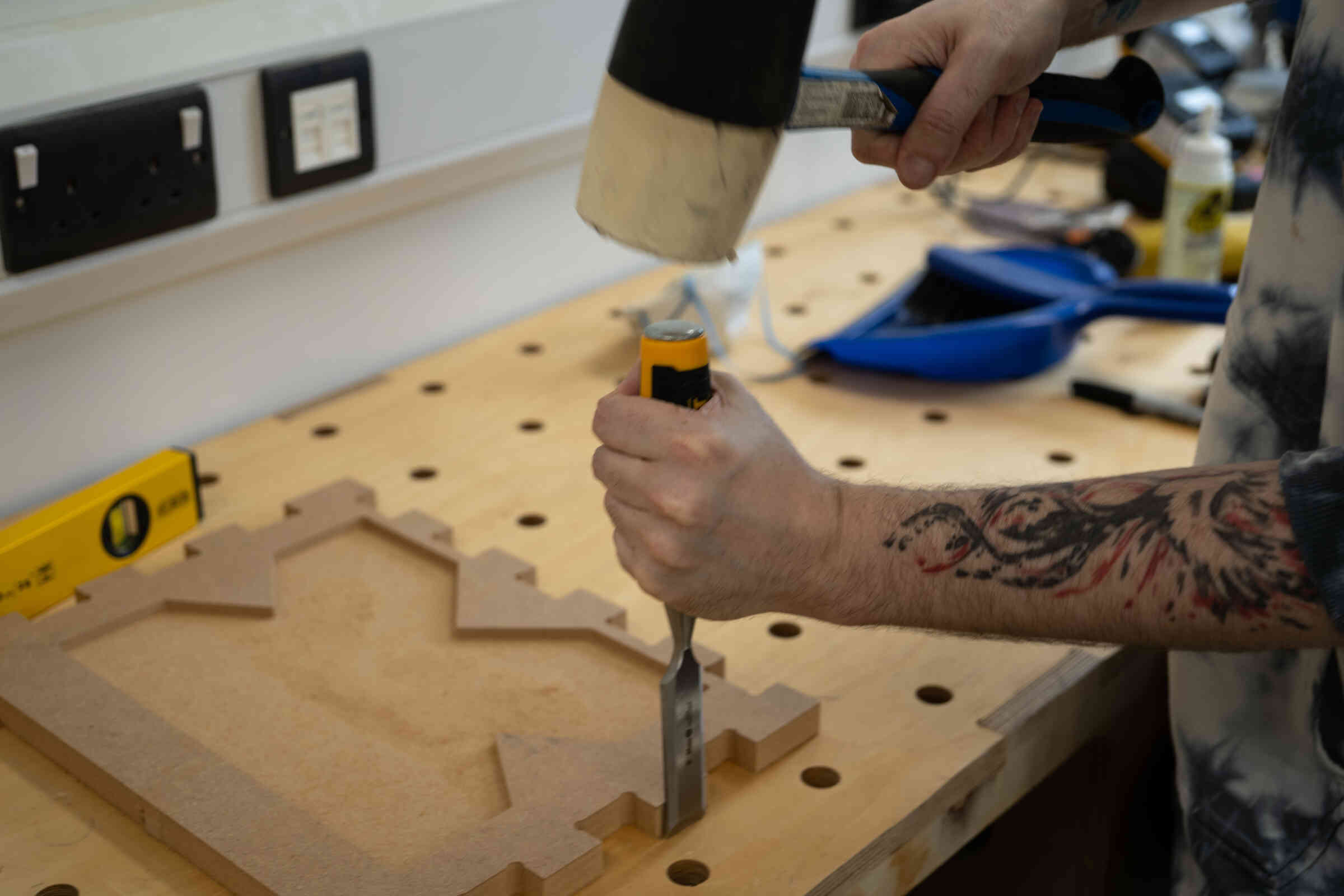
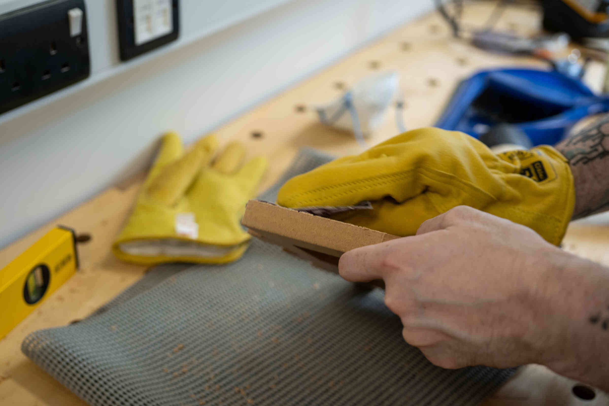
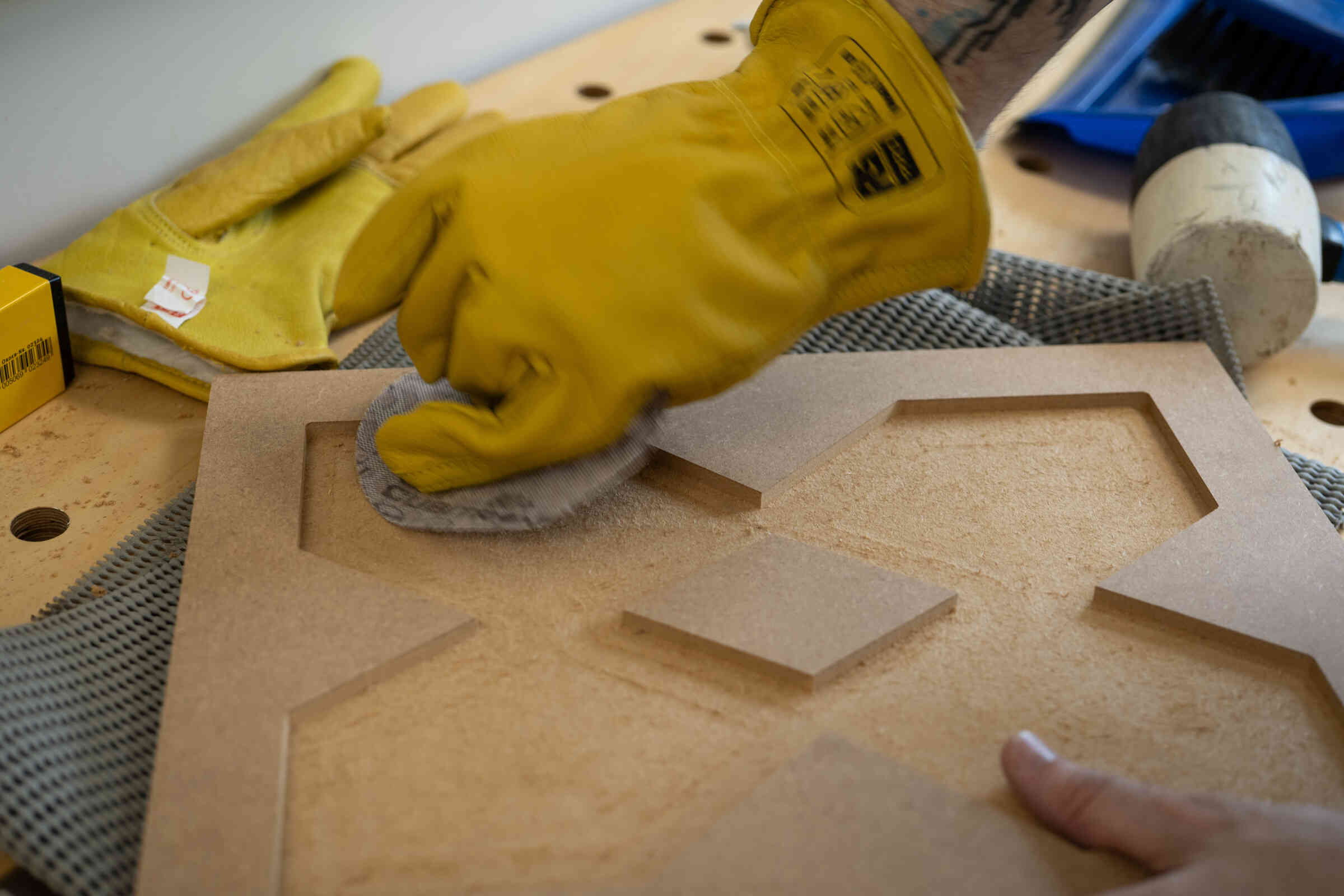
Once the design was carved out (beautifully i might add!), I was able to use a Power Saw cutting tool to cut the tabs holding my pieces together - then used a hammer and flat-end chisel to remove what remained of the tabs.
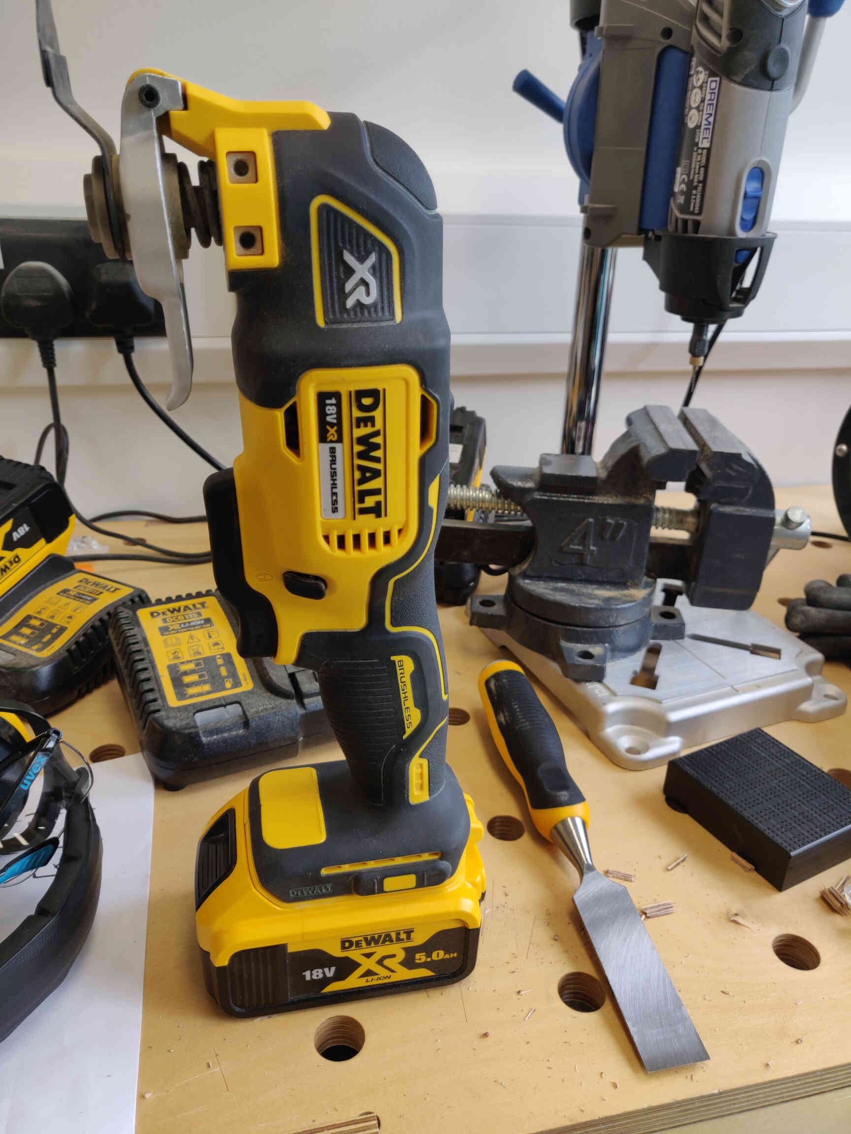

Afterwards I sanded down what remained of the tabs and hovered all the sawdust left everywhere - which was suuuuper satisfying.
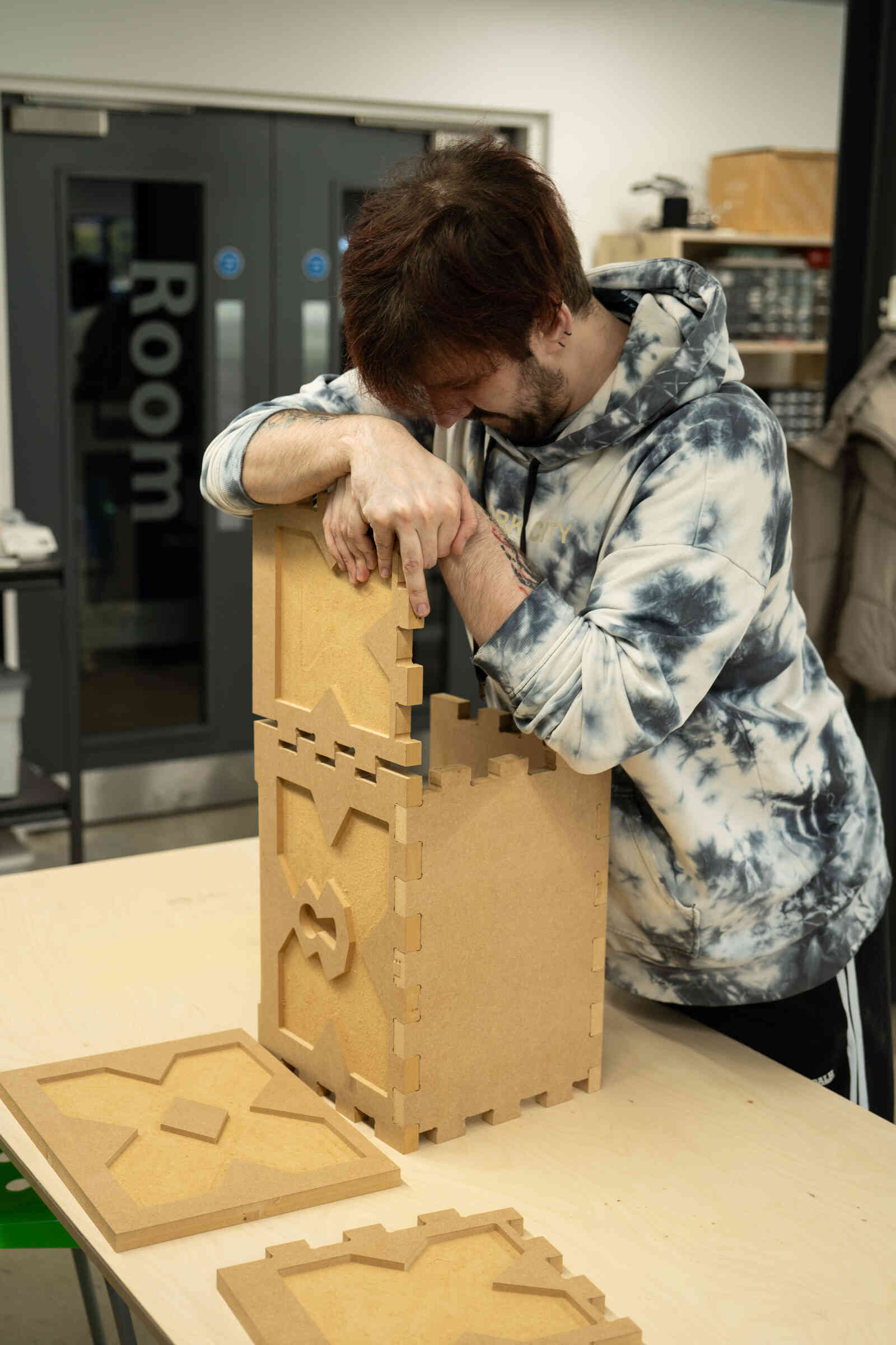
The last thing left to do was stick it all together. I was worried at first because it seemed that the measurements were slightly incorrect and I couldnt fit them together - then Carl came out with a hammer and showed me how it’s done. After a little ‘tap tap’ with the hammer, the pieces fit together perfectly, nice and snug and stable. With that, my ‘make something’ big Treasure Chest assignment was complete!!

____________
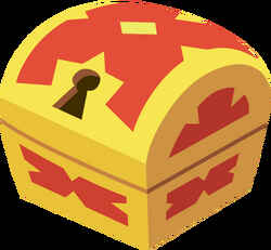
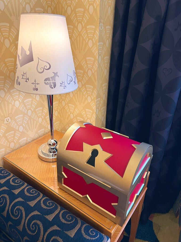
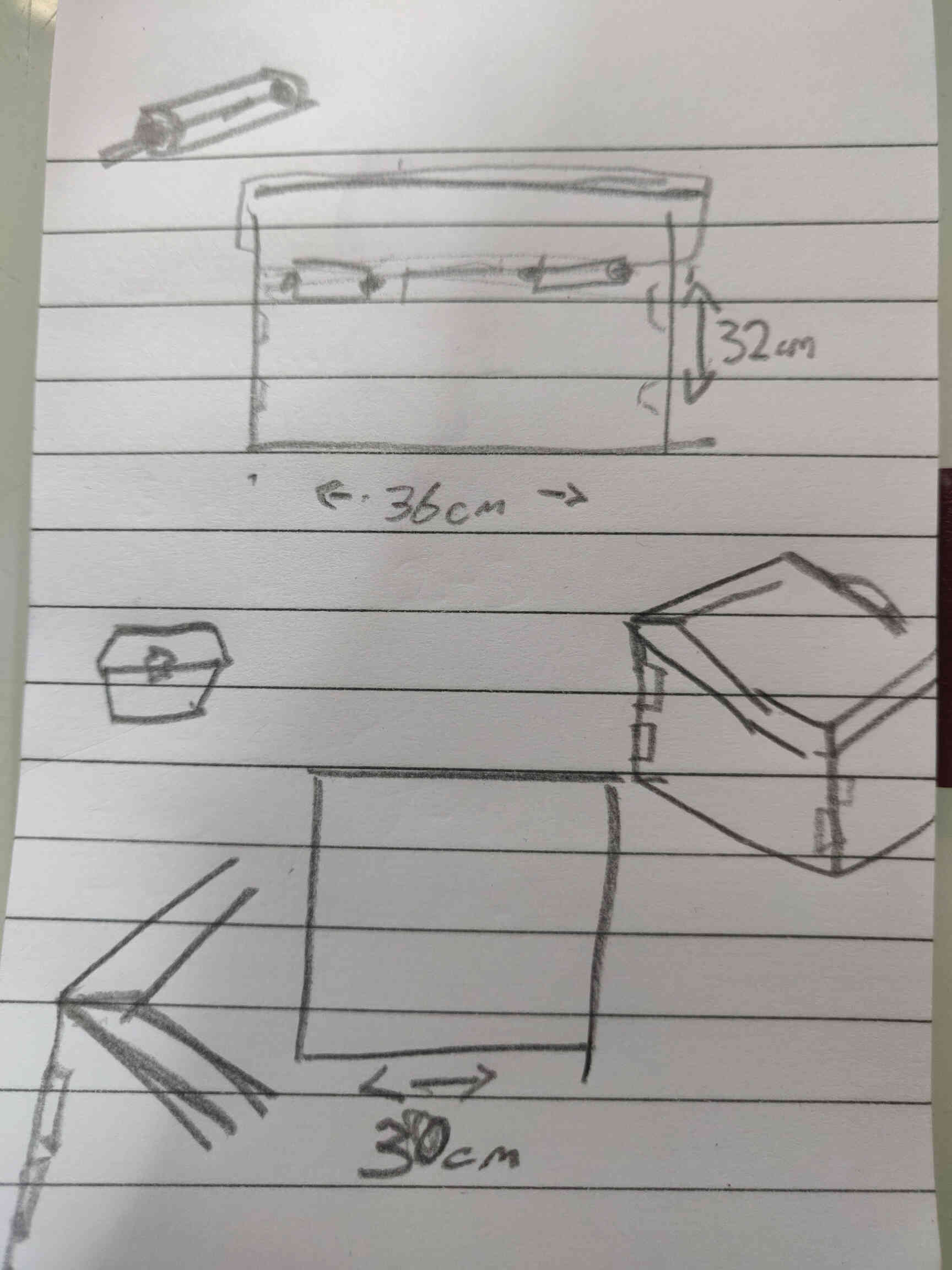
Assignment Concept Research:
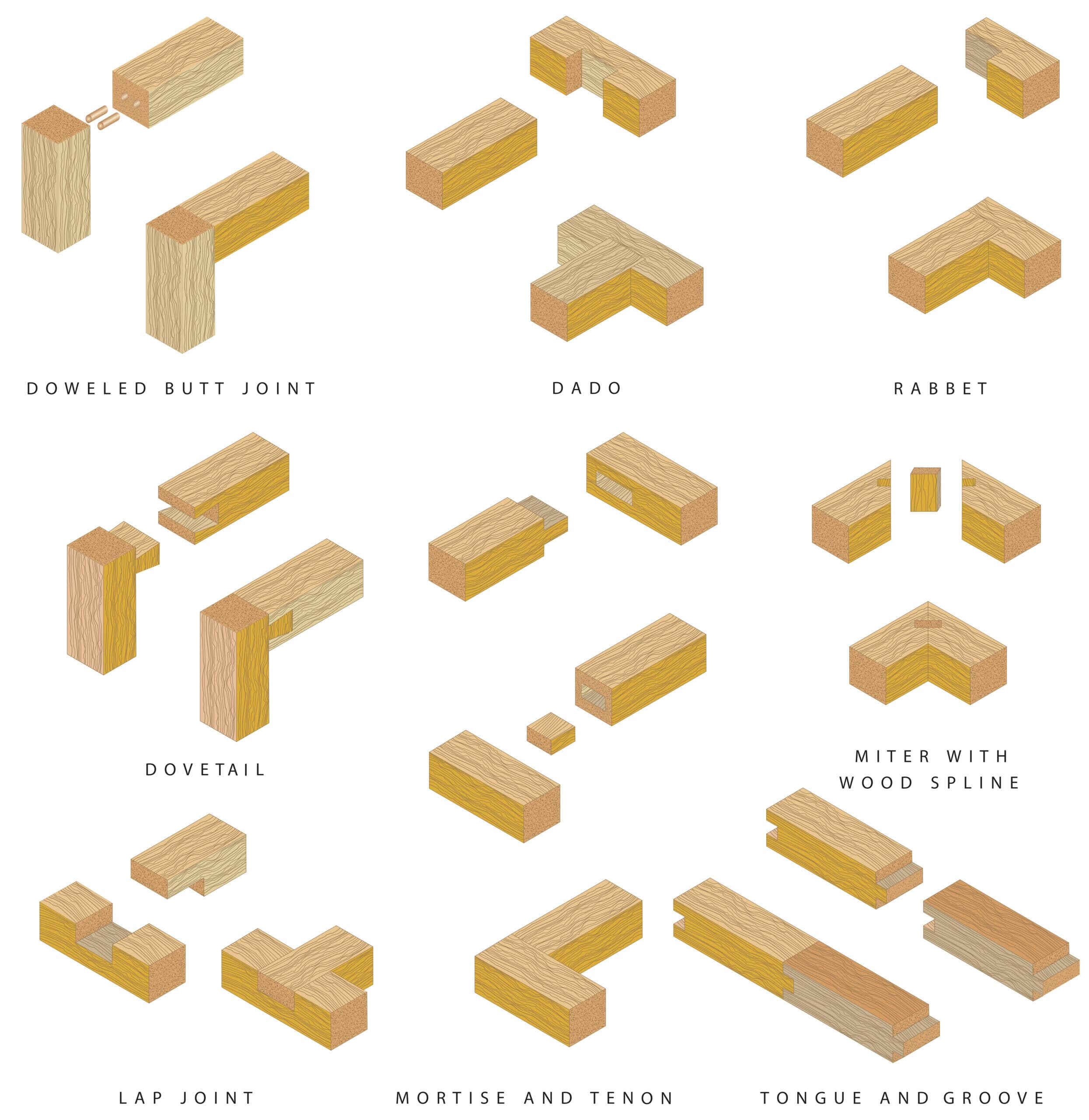
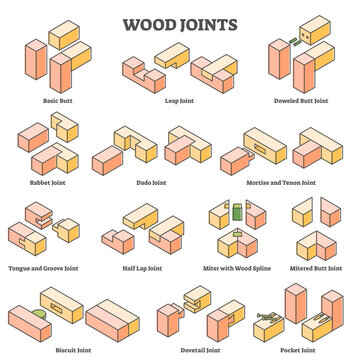
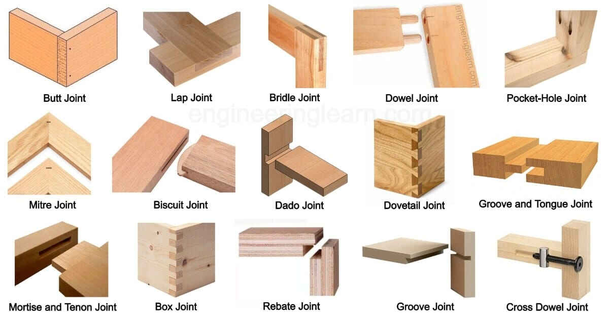
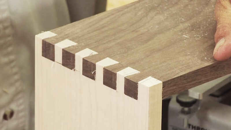
Decided I wanted to make a cartoon Treasure Chest - something that looks ‘not from our world’. I created a concept design sheet of how I want it to look. Also looked at different types of joints that I could use and how they could be designed & nested in 2D CAD software. If my design would be too complicated to make using a CNC machine - or take too much time, effort and cost, then I have several ways of ‘dumbing down’ the design - making it simpler for the machine and myself.
Discussed concepts with my instructor and local technician. We talked through various options for the process including design complications, software & machines I plan to use and joint designs. My initial plans were to use Fusion 360 to create a 3D design which would then be milled using the ShopBot machine.
However after weighing the options and guided through how this type of milling process goes, I ultimately decided that I would use the website MakerCase to create and download a box template, which I would then import as an SVG of DXF into Rhino software to make 2D parametric designs. Then bring those designs into VCarve to convert into g-code and send to the ShopBot machine to mill.
____________
Concept Designing
My concept design also went through some changes. It was described to me that creating the upper dome of the chest using the ShopBot would require much thicker material and be very wasteful.
So I settled on a flat top for the chest with updated engraving designs. I also considered creating the box as a base using MDF, then would cut out the extensions made from OSB and join/fasten them on. After seeing how ‘Pocketing’ is done in VCarve, I decided to have the engravings as part of the MDF Base - meaning less material needed or wasted, less weight and more likely to get extra credit for “no fastenings or glue”. The sides are also no longer slanted and we are going with finger-joints. It was suggested by my instructor that I should make and download a box template from the MakerCase website, so we can update the design from there.
____________
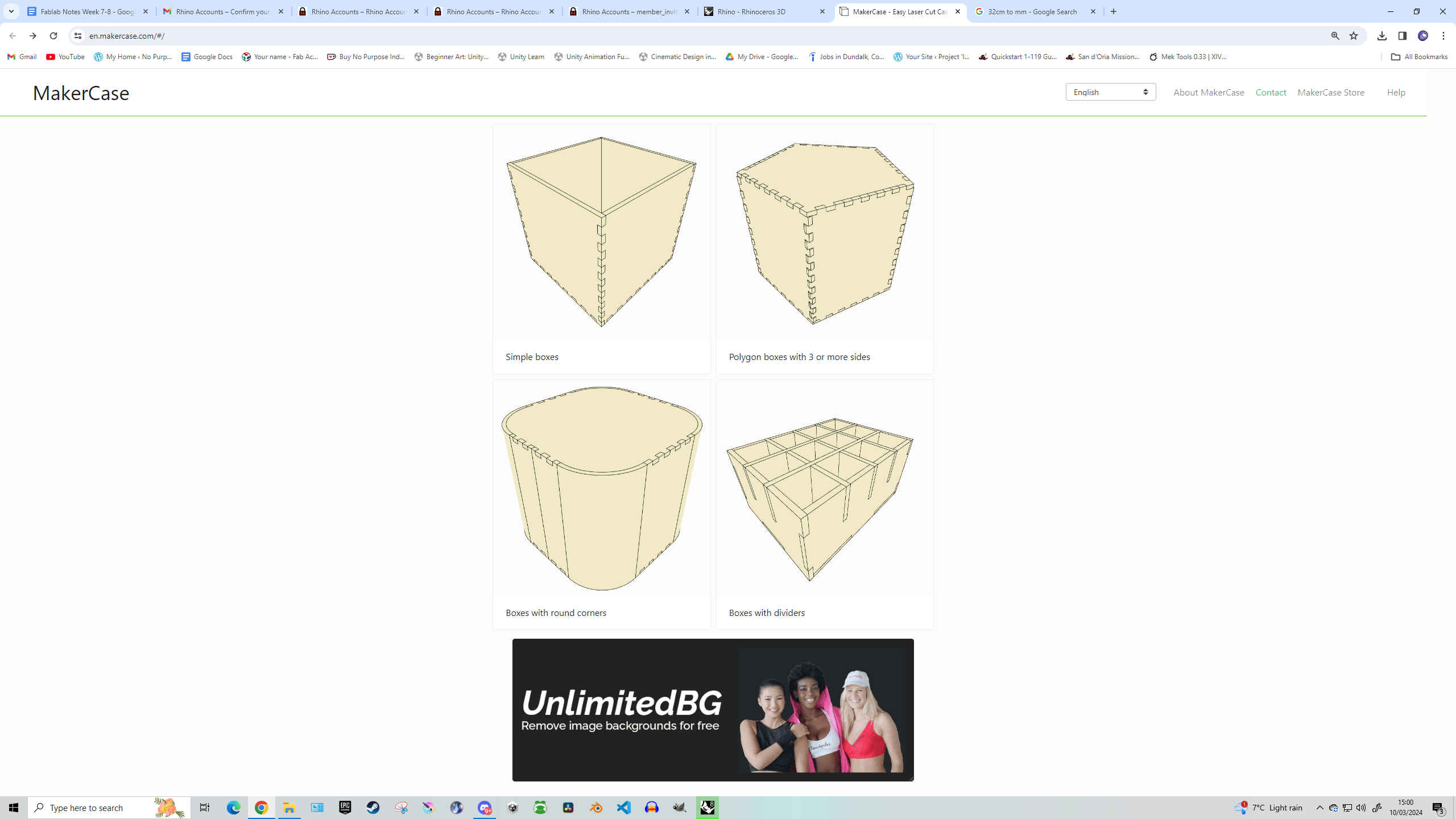
Designing MakerCase Template
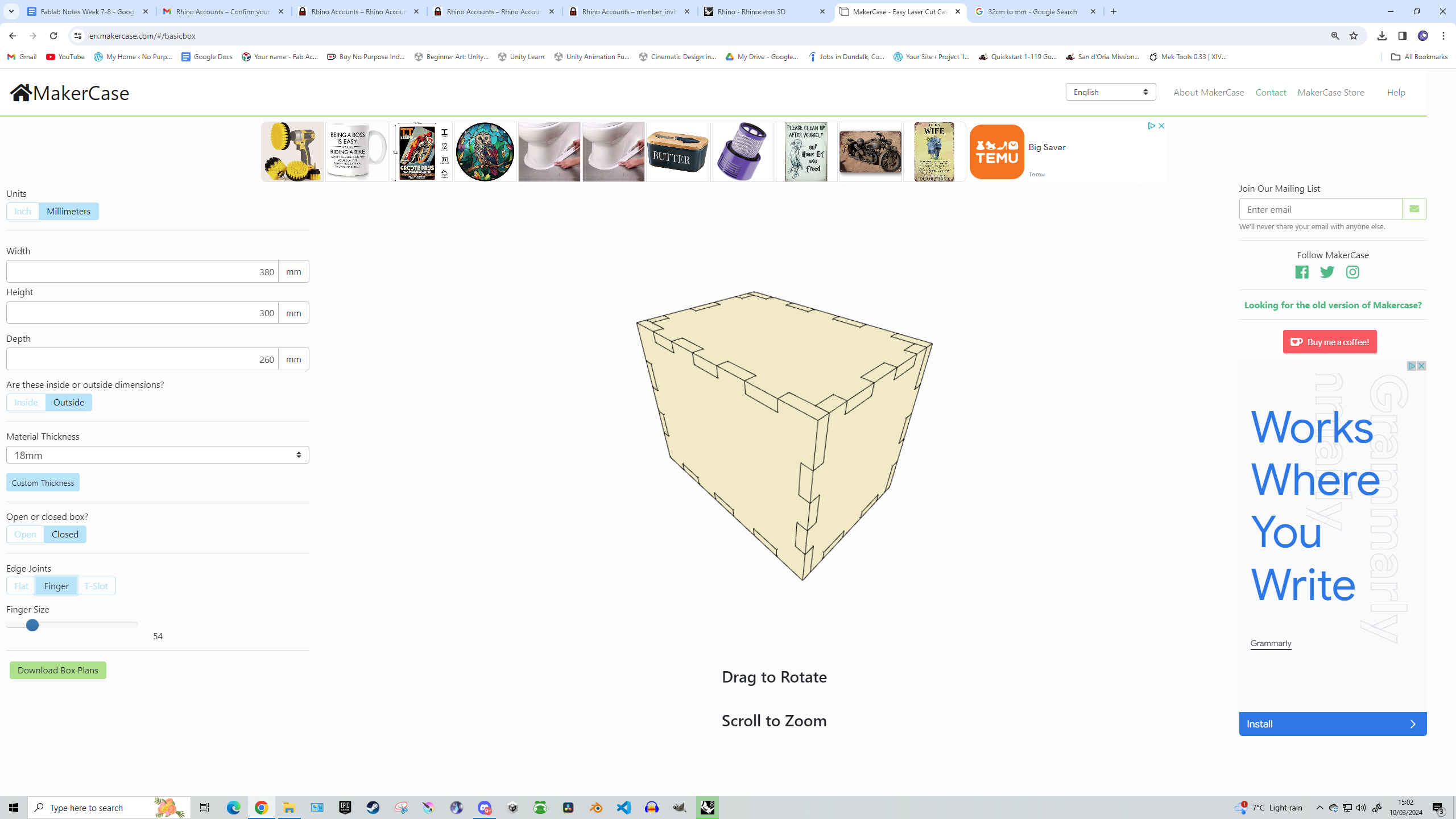
I started making my box template on MakerCase.com. I set the dimensions to:
The dimensions were set to the OUTSIDE. Material Thickness of MDF is 18mm.
Originally I set it to be a ‘closed’ box, but I didn’t want the top of the chest to have finger-joints as I felt it takes away from the Treasure Chest look, so I set it to OPEN - choosing to design the top myself so that it will sit on top of the box can can be opened with a hinge later on.
Set Edge Joints to ‘finger’ and Finger Size to 36.
Afterwards I downloaded both the SVG & DXF files, though the intention was to bring the DXF file into Rhino3D.
____________
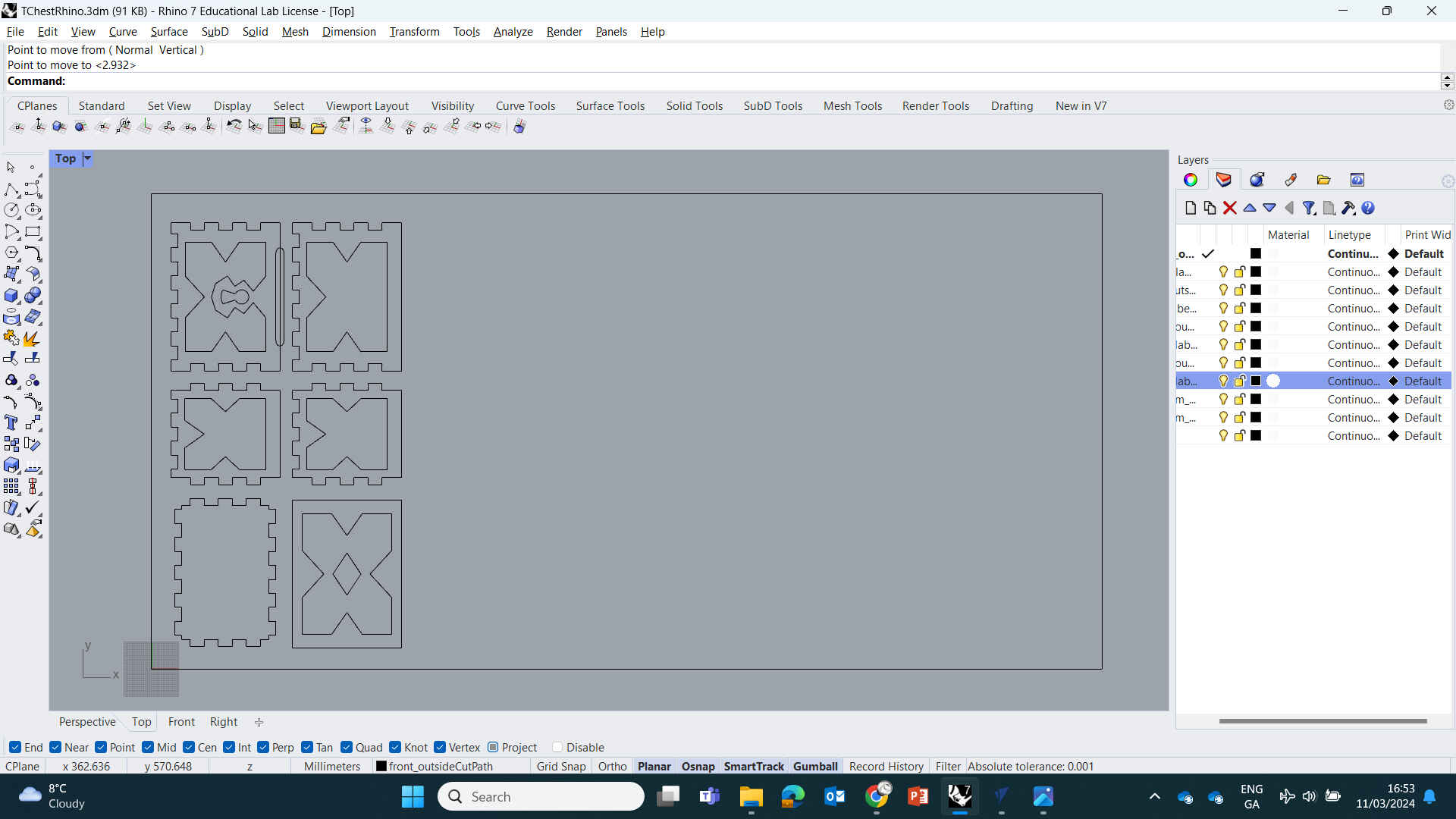
Design in Rhino
First off, open your MakerCase Template DXF file in Rhino. You should be able to quickly identify which panels belong on which sides of the box if you left the names in. We are missing the top (lid) of the chest, but we will design that later. Each panel (excluding the bottom) contains a similar engraving design, so we can make a template for one side, then copy & edit the design on each of the sides. After bringing the template into Rhino, I set about making my design. Against my own wishes to design the chest with a lot of detail, I chose to keep it super simple as I don’t have a lot of time in the Fablab to operate the ShopBot mill and I didn’t want to put myself under pressure if things go wrong.
For designing in Rhino, we are mainly going to stick to these design tools:
Polyline, Rectangle, Circle from Point and Arc tools.
Also to edit our designs we can use the commands:
Join, Explode and Trim.
Rhino, similar to Adobe InDesign, is fantastic at measuring space, midpoints & distance. A great way to get a concise design is to create lines that act as borders or guides, allowing you to correctly gauge spacing when making your design. Utilizing this user-friendly performance, we can use the simple tools listed above to accurately shape our design.
Updating Our Design in Rhino
Using Polylines, add a straight corner to the top left & bottom right corner - this will be our reference guides. We need to make a Rectangle going from the top-left to the bottom-right that encompasses all the finger joints. Once placed, you can delete the entire duplicated panel with the finger joints, leaving us with a perfectly shaped rectangle that will act as a Chest lid.Now we will make a Rectangle Border that goes on the inside of our Front Panel design with 20mm spacing on either side. To measure this, I used the Polyline tool to draw a 20mm line on each side, then starting at the top left corner, I used the Rectangle tool to create a rectangle that's the same height & width as the Front panel. Then I clicked on the newly made rectangle, then used the scale options (little square boxes on the RGB Gumball) to scale it down so that each side connects to the 20mm lines we created earlier. When that's done, you're free to delete the 20mm guides (lines we made).
Now select the Polyline tool and find the midpoint of the left & top side of your rectangle, then draw a line going across each midpoint to form a cross intersection. With that done, draw another line going straight across around 20mm above that horizontal line. Select the new horizontal line and in the command menu, type and select “Mirror”. Now click on the middle horizontal line - this will give your Mirror command a reference for where the midpoint is located and how far spaced the mirrored design will be. Then you need to angle the mirror (using your mouse) to place it correctly. Make the mirror line be 20mm BELOW the middle horizontal line.
Now we have our guides, we can start making the pointed arrows on the left, right and bottom of the inner rectangle. Do this by selecting the Polyline tool and simply draw two lines forming the arrow using our guides as a measurement reference.
(Creating Keyhole Design ^)
Now that we have our lines down, we can Delete or use the ‘Trim’ command to delete the reference guides & inner arrow lines - this can be easier with the Explode & Trim commands - allowing you to delete jointed sections of your design. The ‘Explode’ command is basically the opposite of the ‘Join’ command. Exploding your design will separate all the connected line joints into individual shapes, making it easier to remove unwanted lines. When finished, Drag Select your inner design then type & enter the ‘Join’ Command to join all all the lines into one shape.
(Creating Keyhole Design ^)
Note: If any lines are still disconnected, then there might be a open space hidden between you joints. Find the parts that aren't connecting, then zoom in really close with the mouse wheel until you see the gap. Then use you mouse/selection tool to click and Drag the lines into place. Then zoom back out, select all the lines you wish to connect, then enter the ‘Join’ command again.
(Creating Keyhole Design ^)
Copy & Paste your inner engraving designs from earlier and add one to the new “top” panel.
We will make 2 simple additions to this inner design. Using the methods I detailed above, add an arrow to the top line pointing inwards like the others. Then add a diamond shape directly into the middle using the rectangle or Polyline tool.
Using the tools and methods as detailed above, I created the Keyhole, Front Finger holes, Orgaainzed designs for Nesting, then selected all and exported design as DXF.
____________
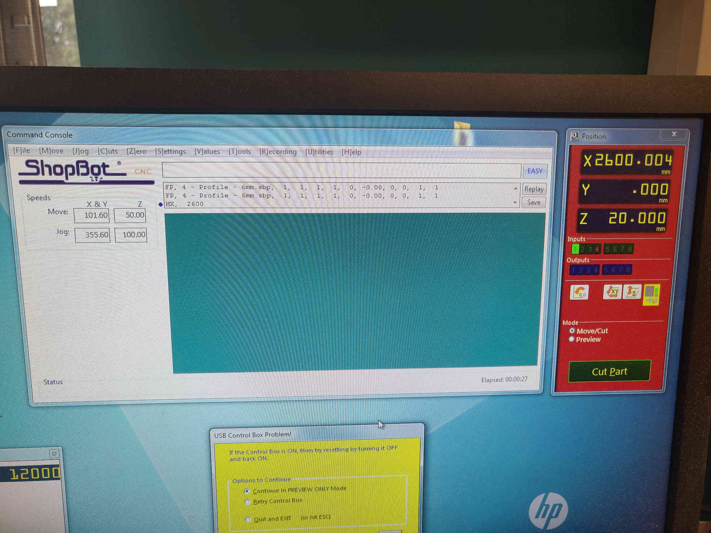
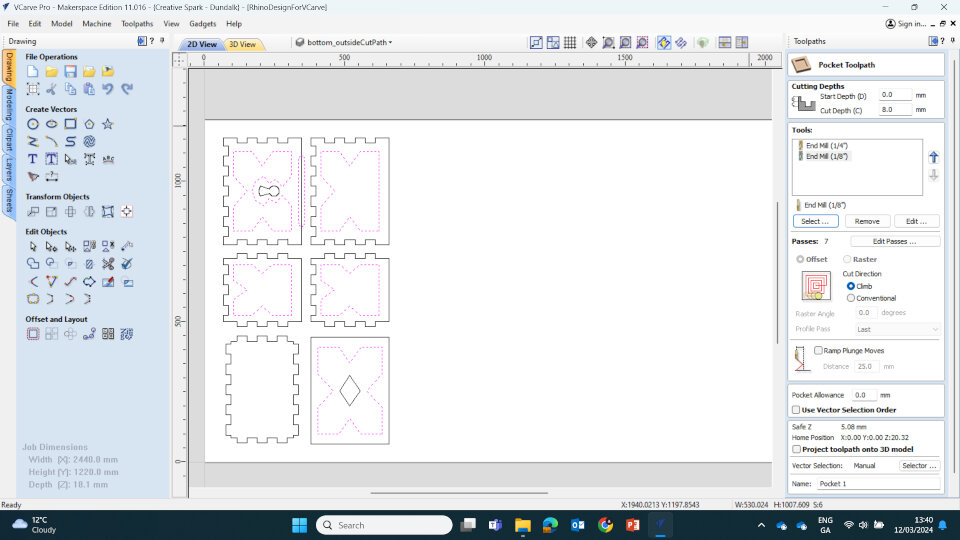
VCarve Notes:
Job size is the size of the stock. Change to the Actual. Roughly 50mm padding around object for screws/fixturing. Set Rapid / Gaps: Clearance 10mm + Plunge 10mm + Gap above Material 20mm Don’t change Home / Start position unless doing something very specific.Focus on first two toolpaths - Profile and Pocket.
Pass Depth - same as tool depth. Standard Spindle feed 12000rpm.
For Passes use Offset instead of Raster. + Conventional Milling.
Ramp Plunge Distance 50mm.
____________
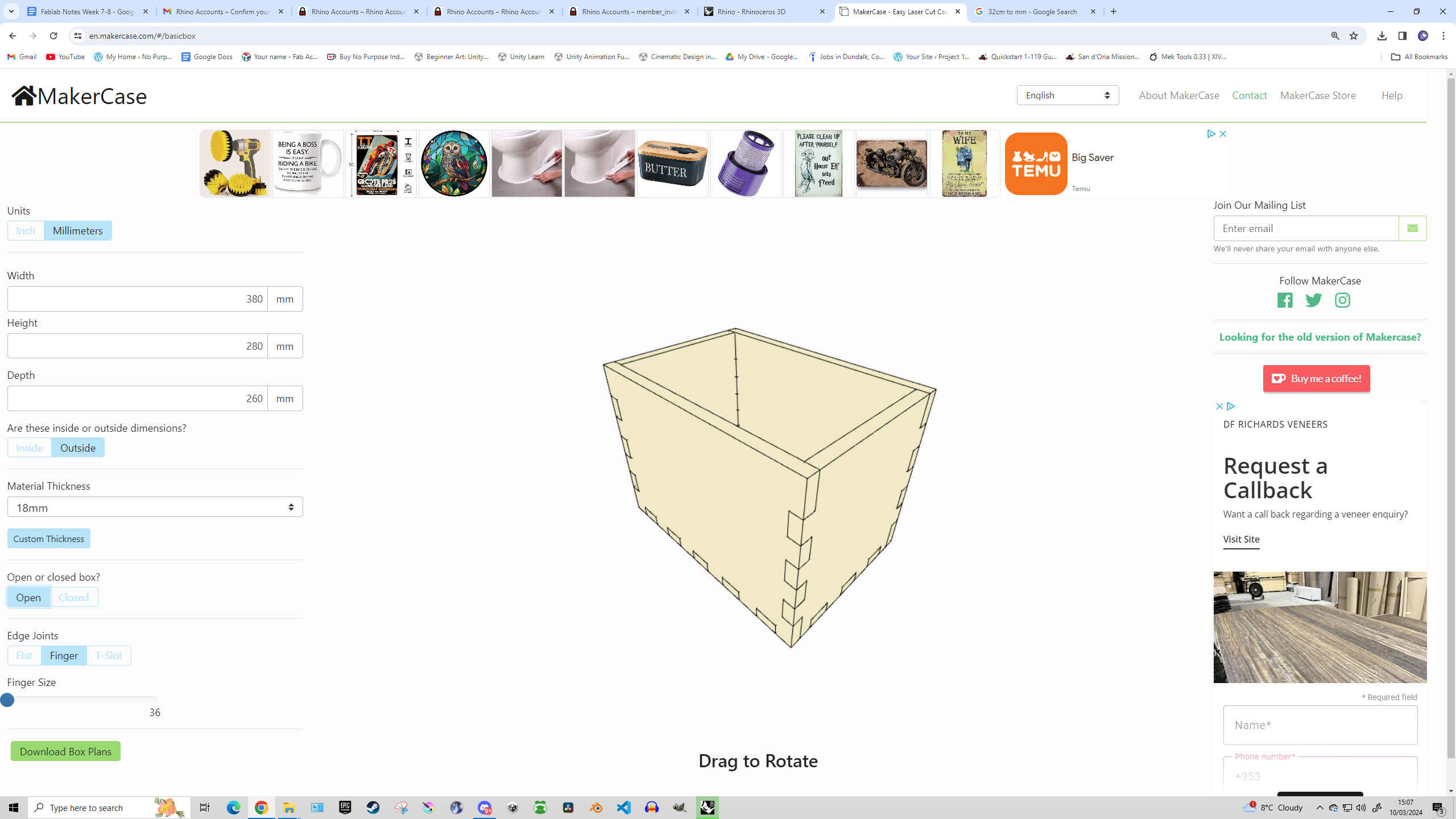
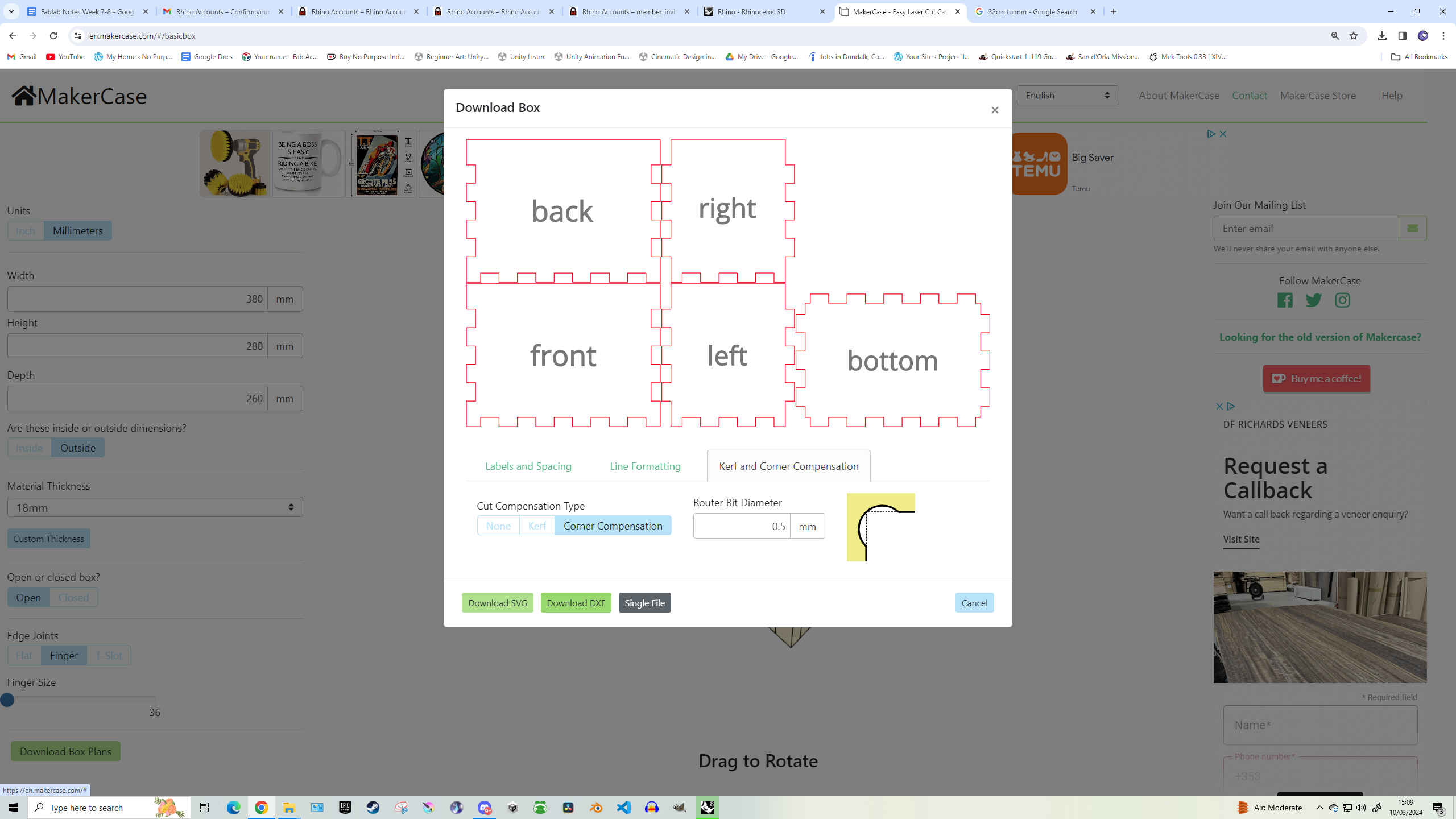
VCarve Settings & Process
Once satisfied with the design and measurements, I saved it as a DXF file and brought it into VCarve. There we discovered a dogbone issue. EDITOR’S NOTE: MakerCase added its own small dogbones into the design (yes it was my fault) and now it wouldn’t allow me to remove them to add proper-sized dogbones through VCarve. So I went back to the design files in Rhino to manually delete all the MakerCase dogbones and rejoin the broken links so that I could add the proper dogbones in through VCarve.
Once that issue was fixed, we selected the lines for creating ‘Pockets’ and ‘Profiles’ - then saved each file, labeling them correctly.
1 - Pocket - 6mm
2 - Pocket - 12mm
3 - Profile - 18mm
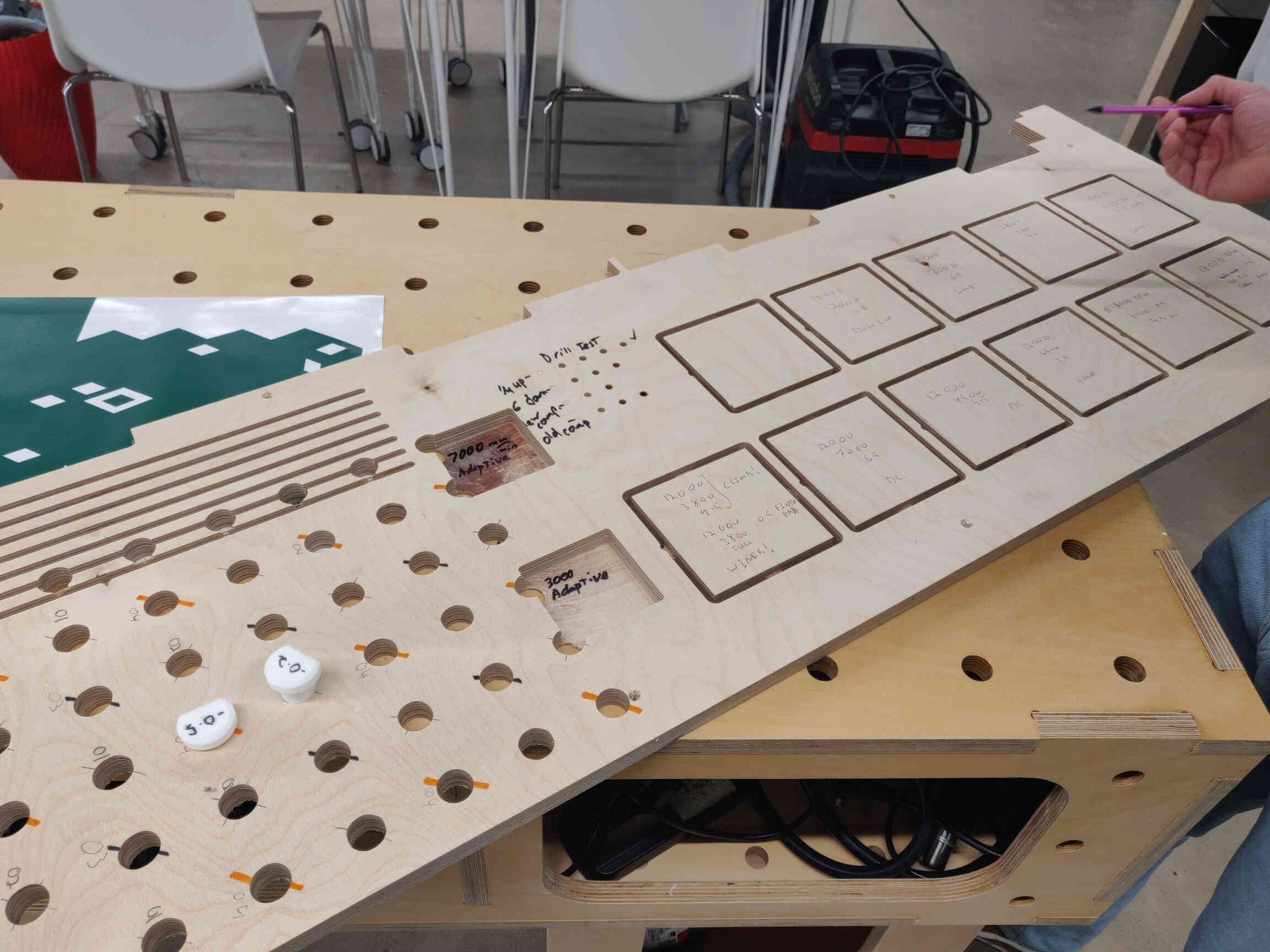
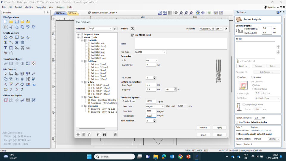
Feeds and Speeds
Pocket Toolpath (End Mill 3mm): Cut Depth 3mm / 2 Passes(Chip load = 0.1mm)
Spindle Speed: 18000rpm / Feed Rate: 3600mm/min / Plunge Rate: 1800mm/min /
Ramp Plunge Distance: 50mm / Cut Direction: Climb
Pocket Toolpath 2 (End Mill 6mm): Cut Depth 6mm / 2 Passes
(Chip load = 0.33mm)
Spindle Speed: 12000rpm / Feed Rate: 7800mm/min / Plunge Rate: 3900mm/min /
Ramp Plunge Distance: 50mm / Cut Direction: Conventional
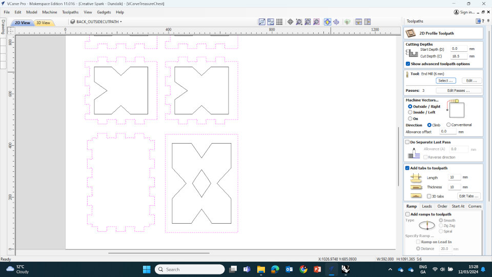
Profile Toolpath (End Mill 6mm): Cut Depth 6mm / 3 Passes - leaving 0.5mm stock
(Chip load = 0.33mm)
Spindle Speed: 12000rpm / Feed Rate: 7800mm/min / Plunge Rate: 3900mm/min /
Ramp Plunge Distance: 50mm / Cut Direction: Climb
Finish Pass: Conventional Cut Direction - Removing the 0.5mm in one pass.
- Add tabs to toolpath: Length & Thickness: 10mm
- Machine Vectors: Outside / Right
Feeds and Speeds Excel Sheet
Below you can find a Chip Load Calculator table in excel that helps you calculate feeds and speeds.Feeds & Speeds / Chip Load Calculator Excel
Dogbones: Dogbones are rounded notches that you add to any and all sharp corners, as it accounts for the size of the End Mill and it's inability to make a perfectly sharp corner. Adding dogbones within VCarve will create outer rounded corners that will allow for a much nicer and smoother fitting & assembly process. These can be added in VCarve by selecting Create Fillets -> Dog-Bone Fillet.
Editor's Note: I added dogbones automatically while making the box in Maker Case as the option was there. However they weren't the proper size that we needed so I needed to replace them with ones through VCarve instead. However, complications arose as VCare couldn't just 'replace' the dogbones - I needed to return to the Rhino DXF files and individually delete every single dogbone and reconnect the corners.
Let this be a lesson - I could have saved myself 2 hours of work and problem solving by just not selecting automatic dogbones within Maker Case.
(Fixing automatic dogbones in Rhino ^)
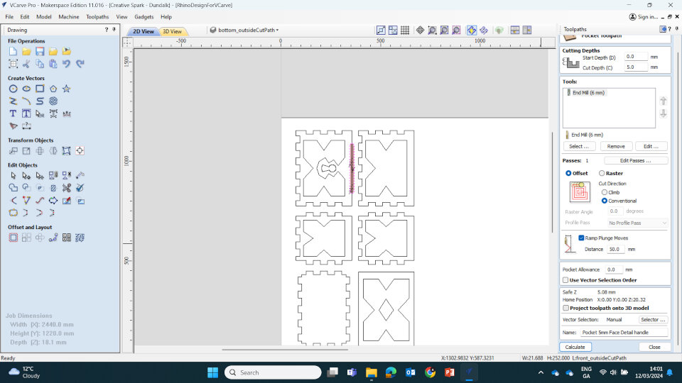
We saved each cut as it's own toolpath files and organised them accordingly:
1-Pocket-12mm-KeyHole
2-Pocket-8mm-FaceDetail
3-Pocket-8mm-FaceInlay
4-Pocket-5mm-FaceHandle
5-Profile-18mm-Cutout
Then we viewed the toolpath simulator within VCarve. Once satisfied, we saved the files and brought them to the ShopBot Machine.
____________
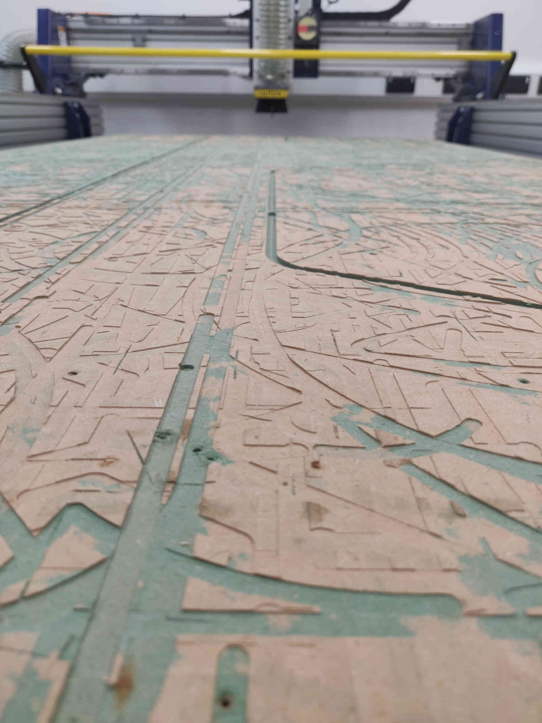
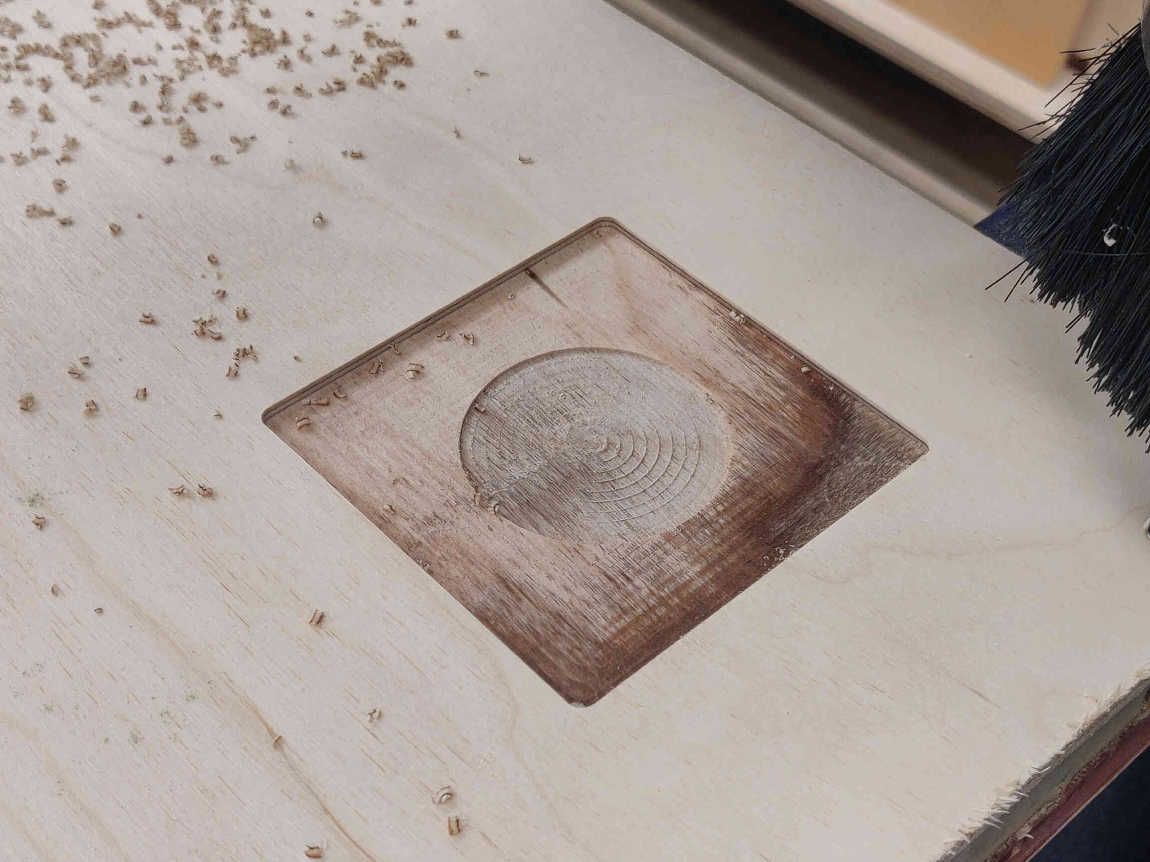
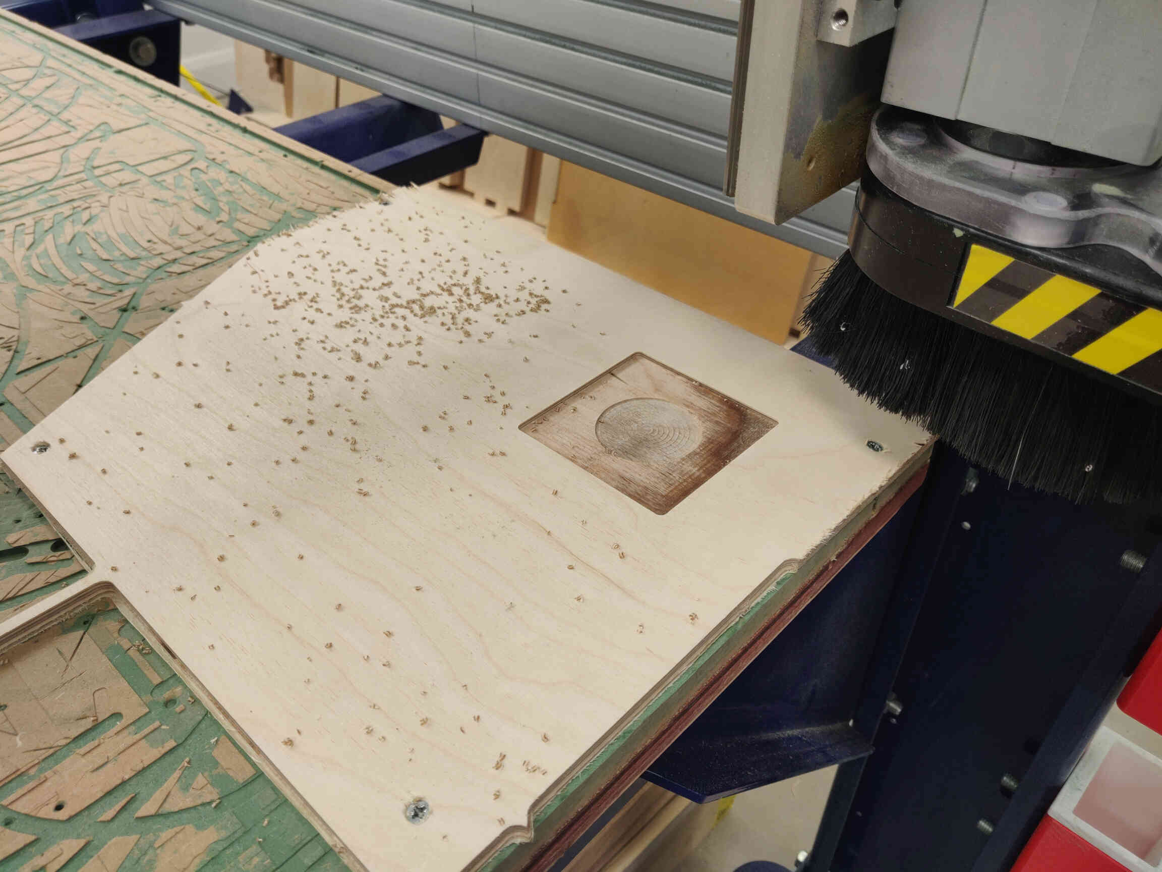
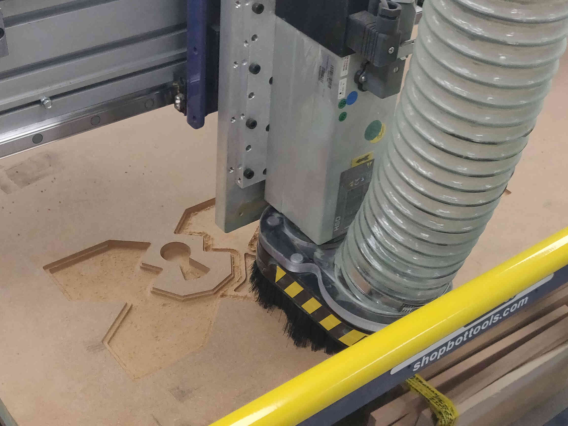
ShopBot Cutting
I was surprised by how easy it was to control / use the ShopBot machine. I felt very comfortable with it but it was stressed to me by several people ‘NOT’ to get too comfortable with it and don’t make it feel routine, as you open yourself up to slight mistakes which could have potentially dangerous/damaging/life-threatening consequences. Because of this, it's very important to review the safety procedures that I highlighted earlier in this week's assignment page.
CNC Videos
Once the design was carved out (beautifully i might add!), I was able to use a Power Saw cutting tool to cut the tabs holding my pieces together - then used a hammer and flat-end chisel to remove what remained of the tabs.
Afterwards I sanded down what remained of the tabs and hovered all the sawdust left everywhere - which was suuuuper satisfying.
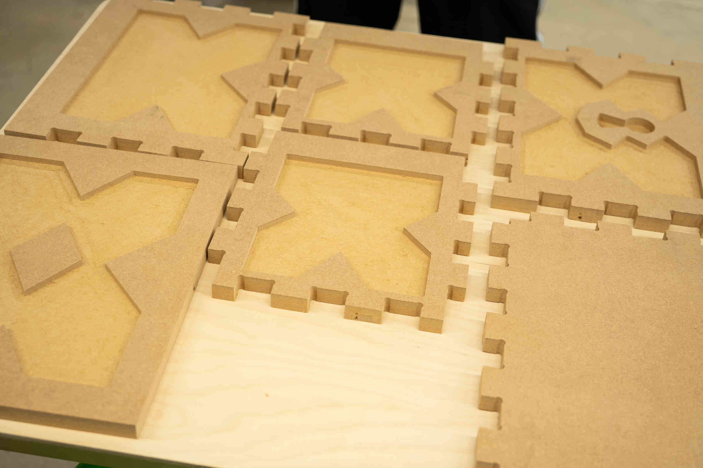
The last thing left to do was stick it all together. I was worried at first because it seemed that the measurements were slightly incorrect and I couldnt fit them together - then Carl came out with a hammer and showed me how it’s done. After a little ‘tap tap’ with the hammer, the pieces fit together perfectly, nice and snug and stable. With that, my ‘make something’ big Treasure Chest assignment was complete!!
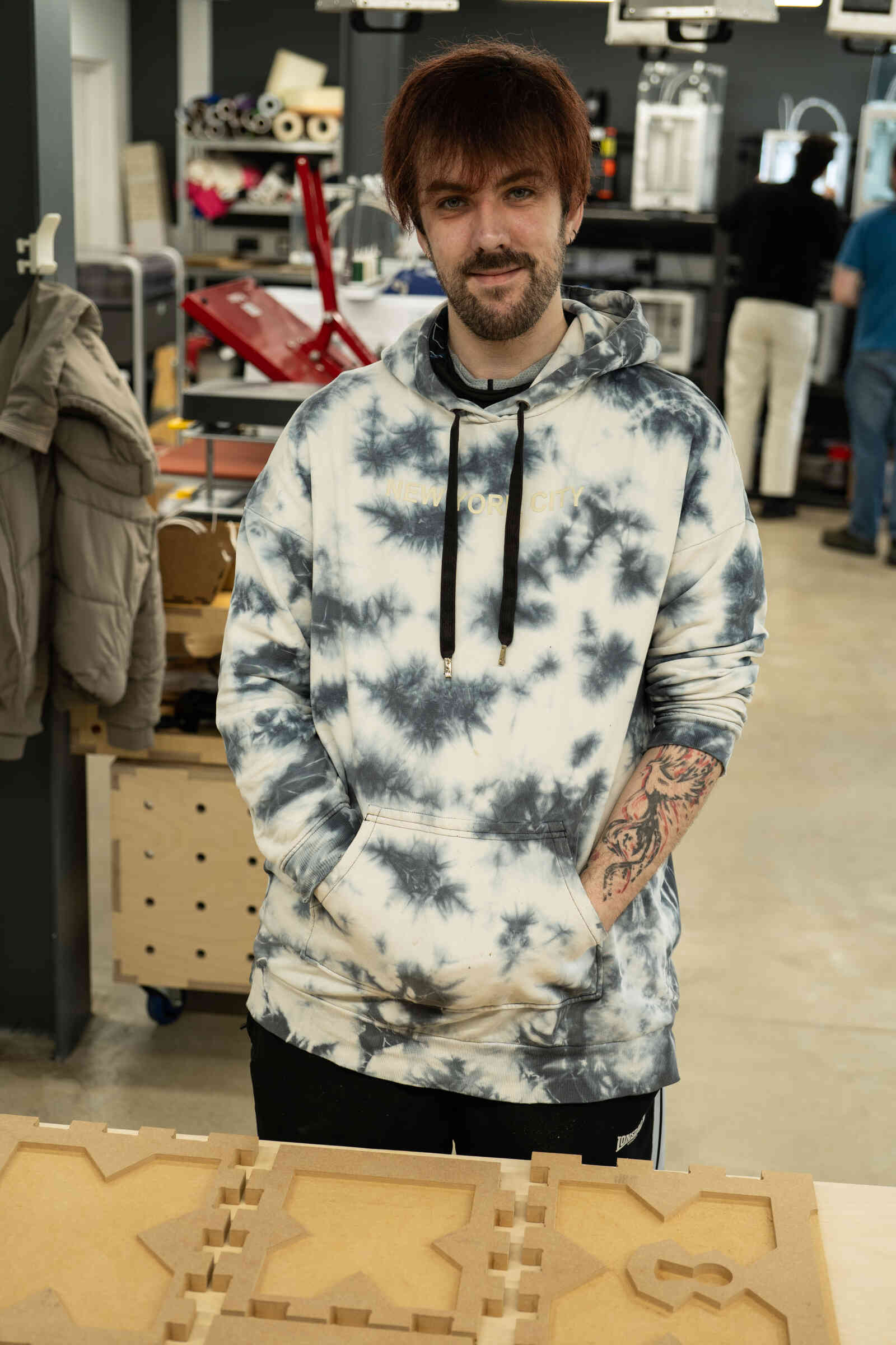
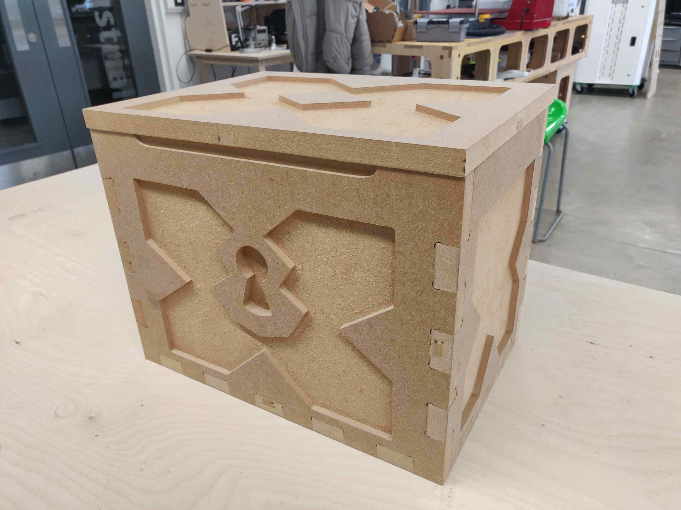
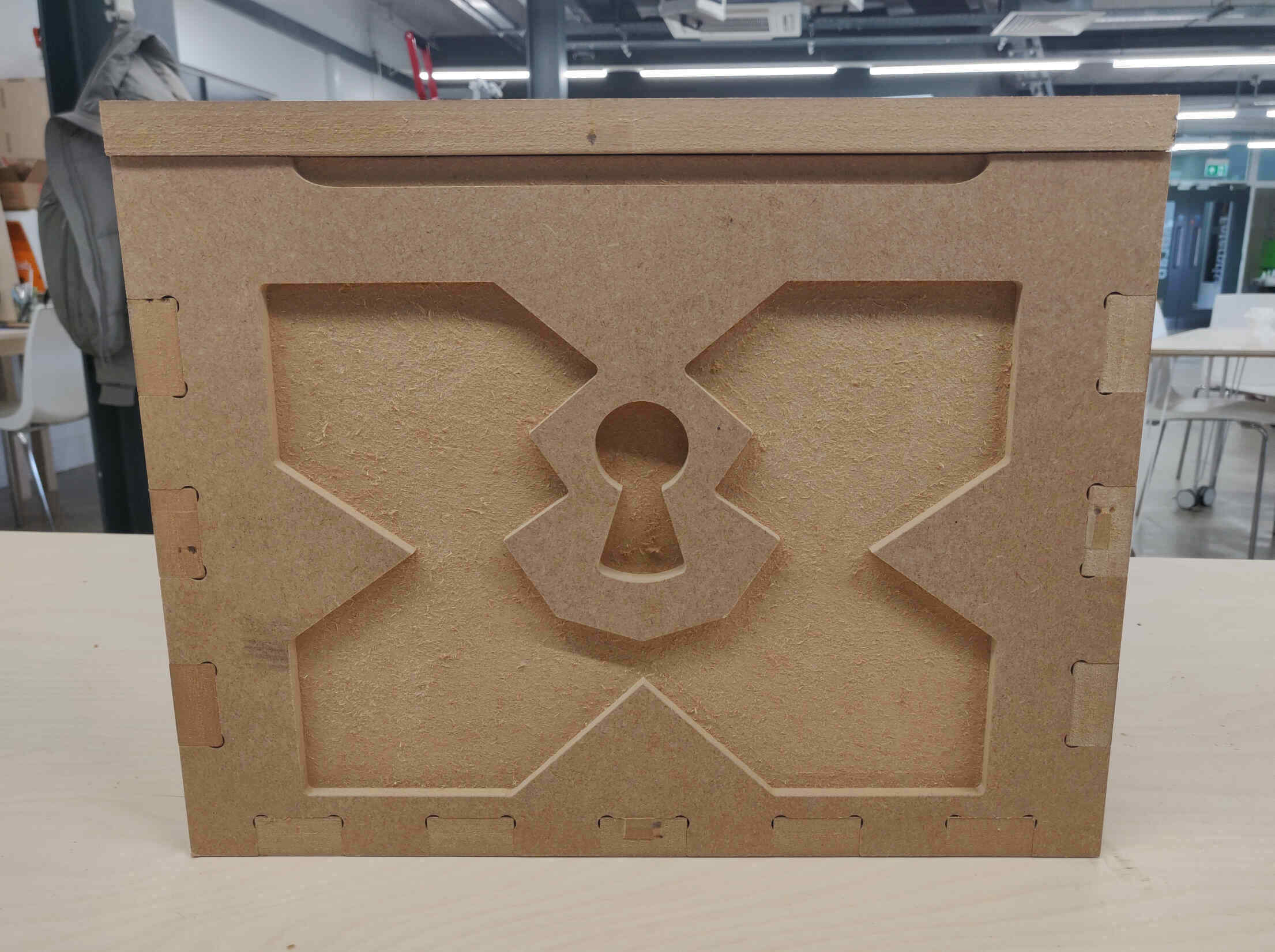
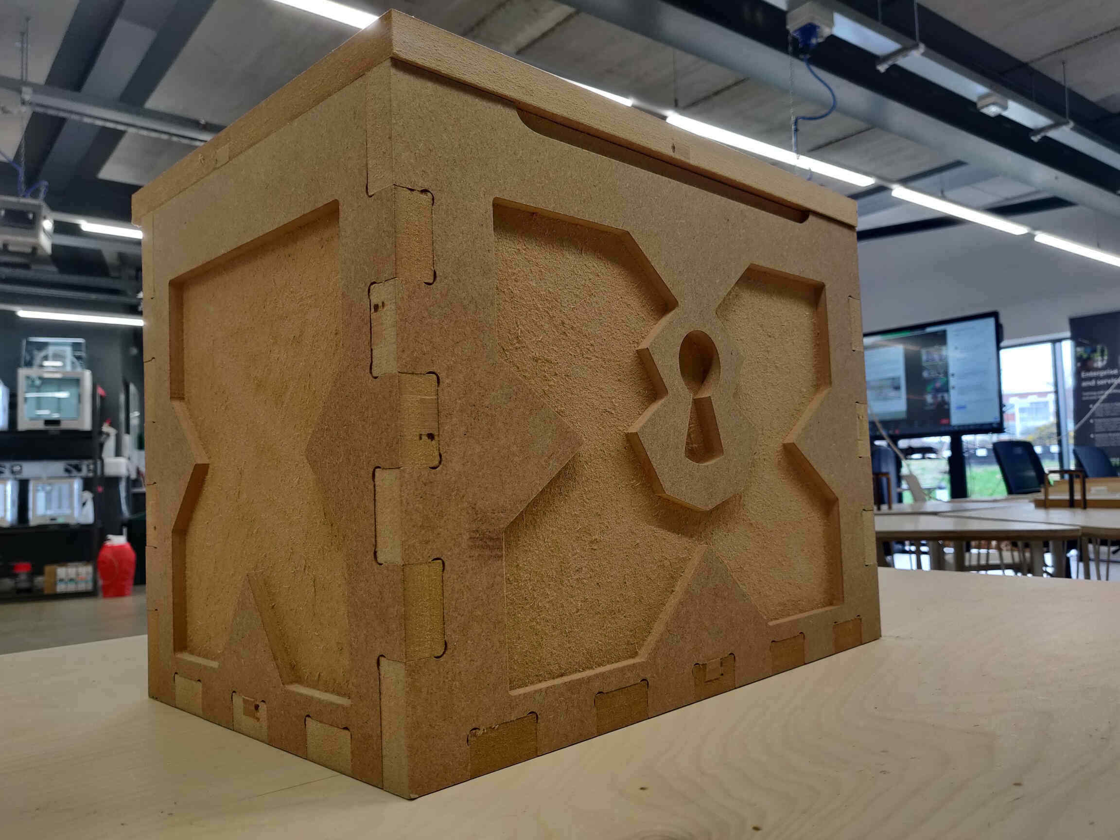
Finished Product:
____________
Conclusion / Reflection
Operating CNC machines throughout this course has been truly worthwhile as it uses my 2D designs to create something 3-dimensional in real life and in a way that’s very easy to understand. As intimidating as the ShopBot machine is - it’s actually very simple to use. Concept Design I was happy with my concept design revisions as they allowed me to create something properly prepared and measured without much change in the production process, MakerCase was a fantastic discovery as it allows me to have a straightforward base to whatever I want to make and is easy to change or manipulate in Rhino. I will eventually want to discover ways of implementing purely 3D designs and curved surfaces using these machines, but right now it allows for a lot of mixed media after cutting. Also, now that I understand how to easily implement dogbone fillets in VCarve, I’ll be sure not to add them automatically in MakerCase.Rhino continues to be incredibly user friendly for designing and manipulating my designs for cutting on many different machines like milling, laser cutting, waterjet cutting, etc.
VCarve seemed overly technical as preparing correct measurements and toolpaths is often quite intimidating for me, but once I understood how to navigate the software it became much easier to understand and control the result you want.
The ShopBot CNC machine was my very first heavy machine operation. As mentioned before, it seemed intimidating at first but thanks to the detailed step-by step safety procedure documentation, it quickly became simplistic and by the numbers. Though it was stressed to me that ShopBot machines aren’t something you want to be overly comfortable with as a single mistake can lead to devastating consequences. I’ll be sure to keep this in mind whenever I operate the machine.
This was a very satisfying week with a highly satisfying result. There’s still much more I can do with my treasure chest - sand down the surfaces and edges, add colour through spray painting, add a hinge to the lid and add metal surface plating, etc.
____________