Group Assignment:
Group Assignment Link:
____________
Group Assignment
Practice & Research into 3D Slicer applications


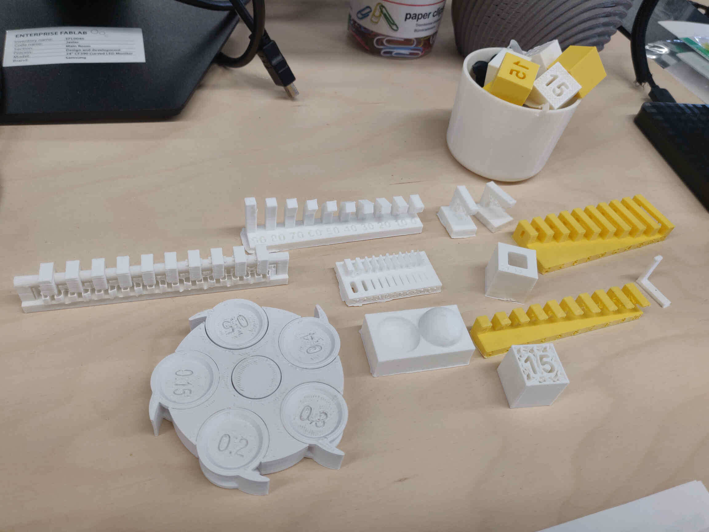
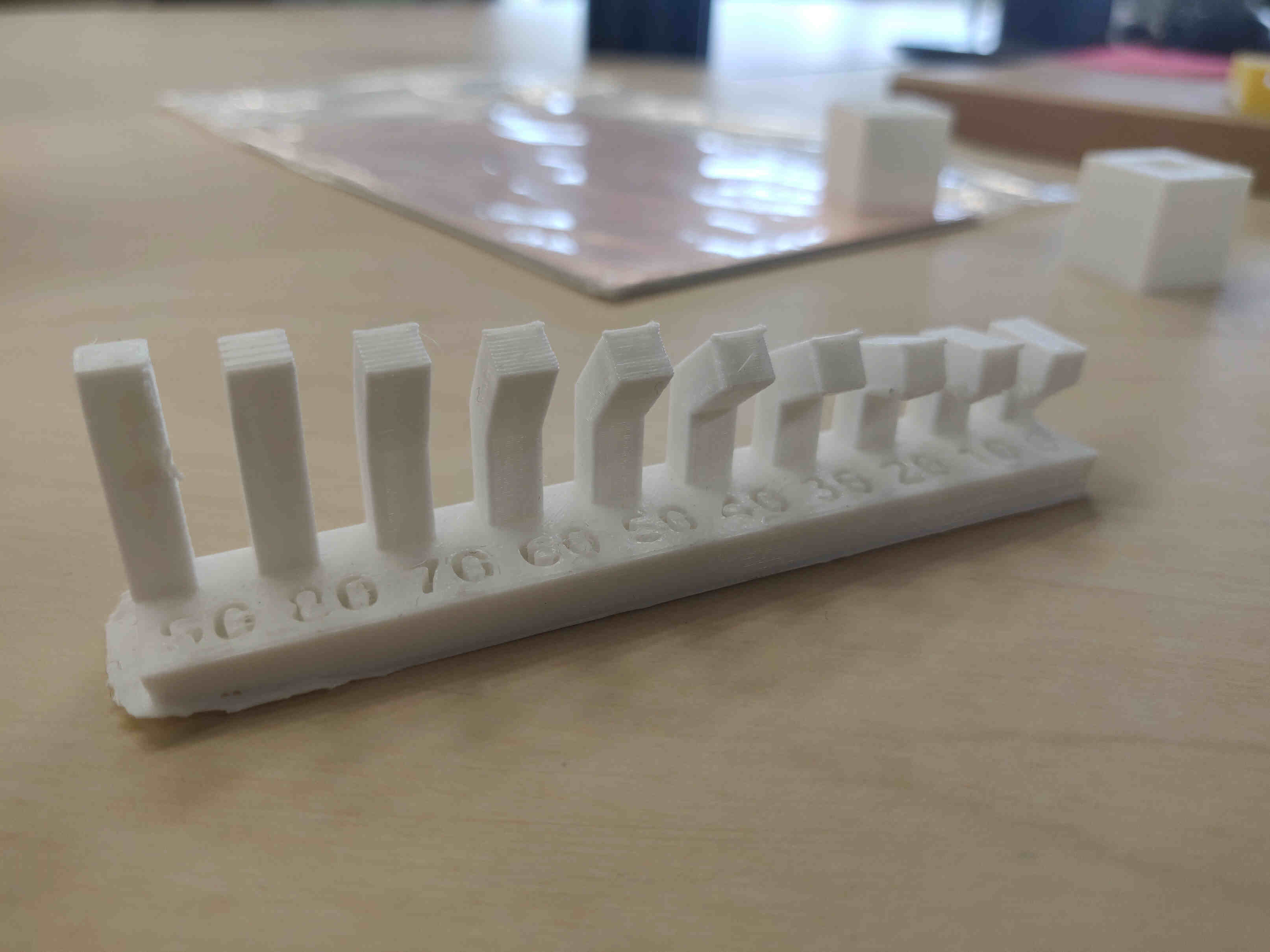
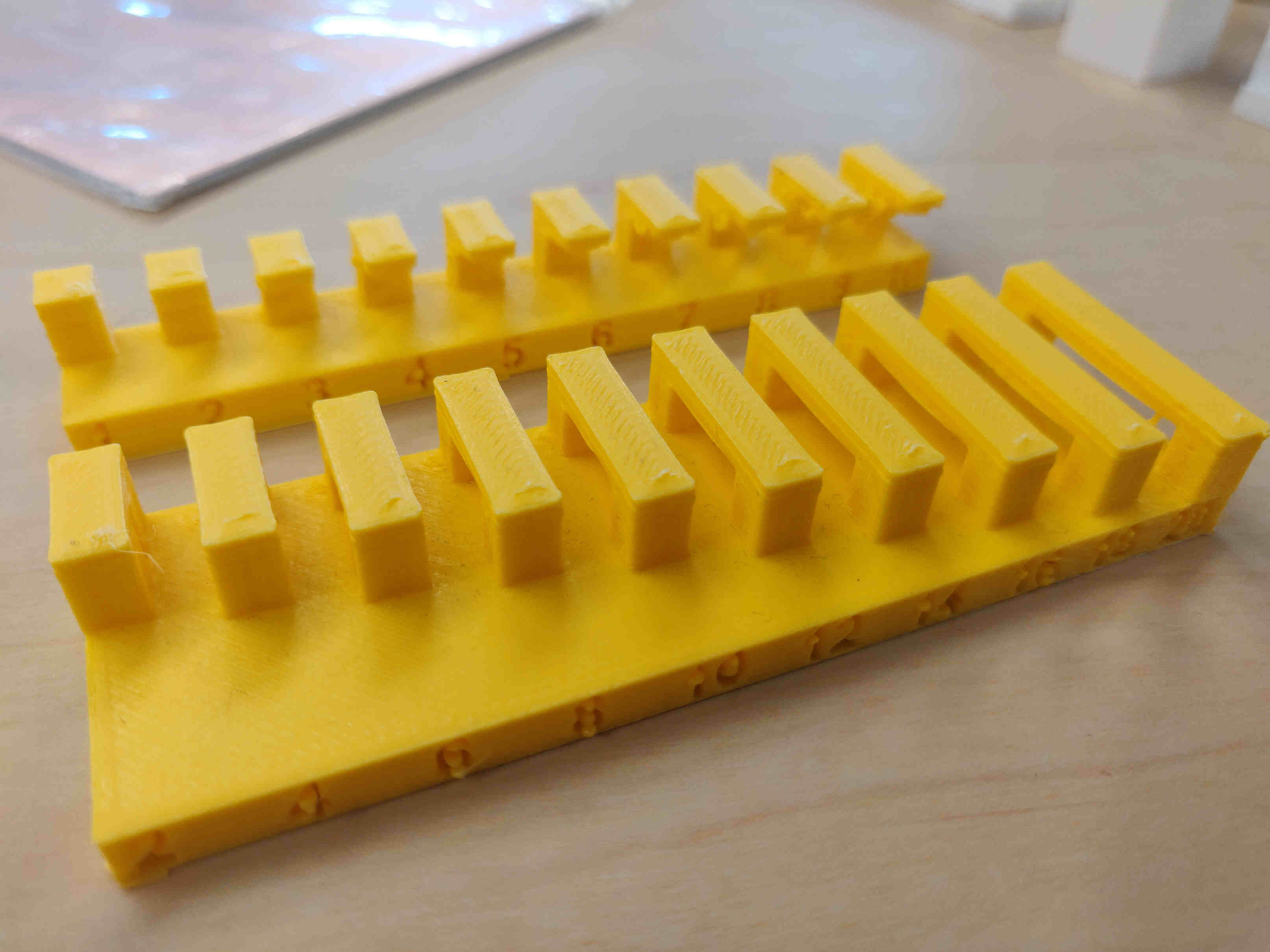
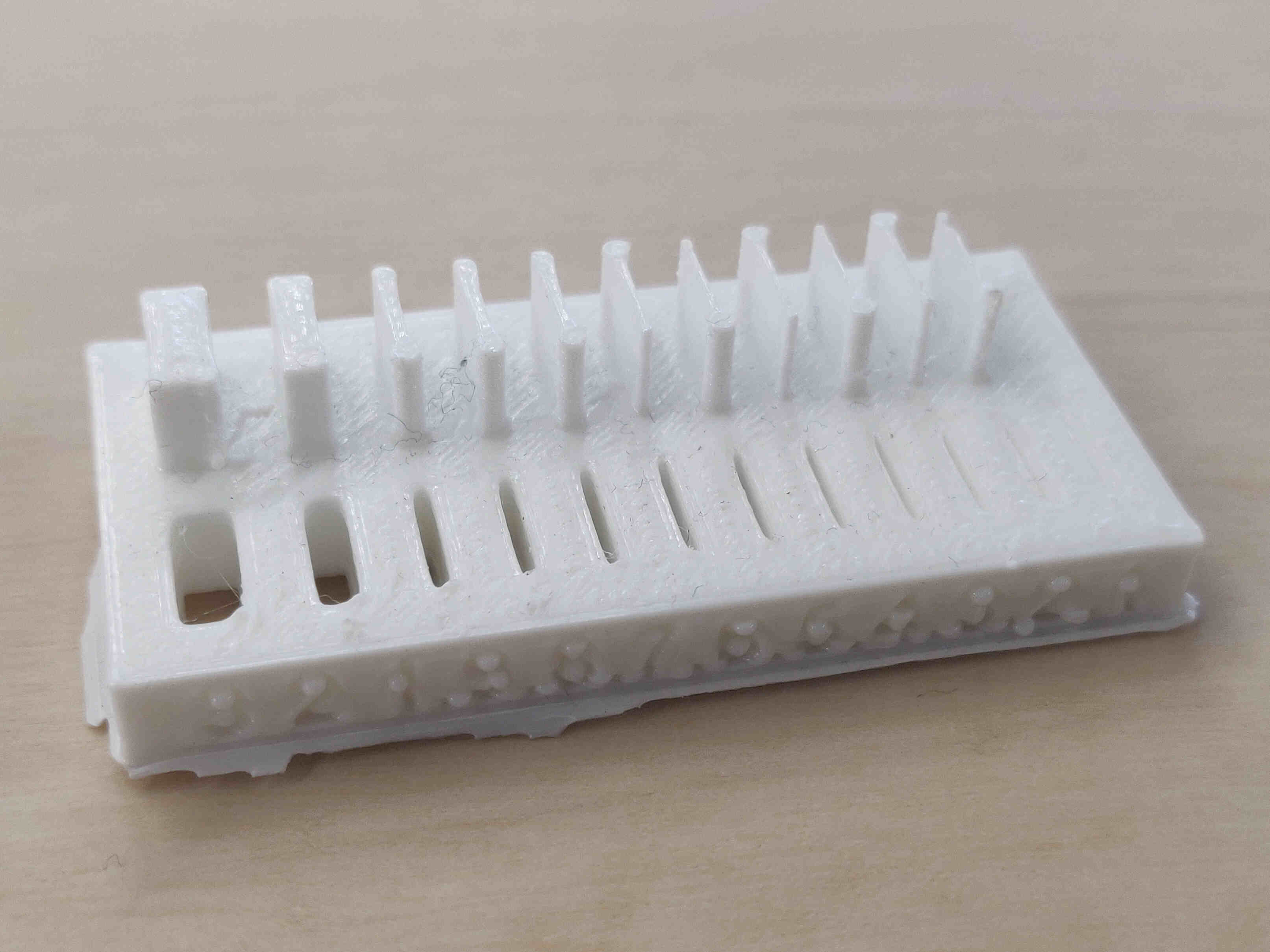
I first attempted to print everything at once for time management, I quickly saw how it can affect the result. Above is an image of a completed print test on clearances above a failed test. With help of my newly formed group, we were able to individually print each example that shows the result of clearances, overhangs, infill percentage, nozzle width, etc. Oscar gave me a crash course on each of them.

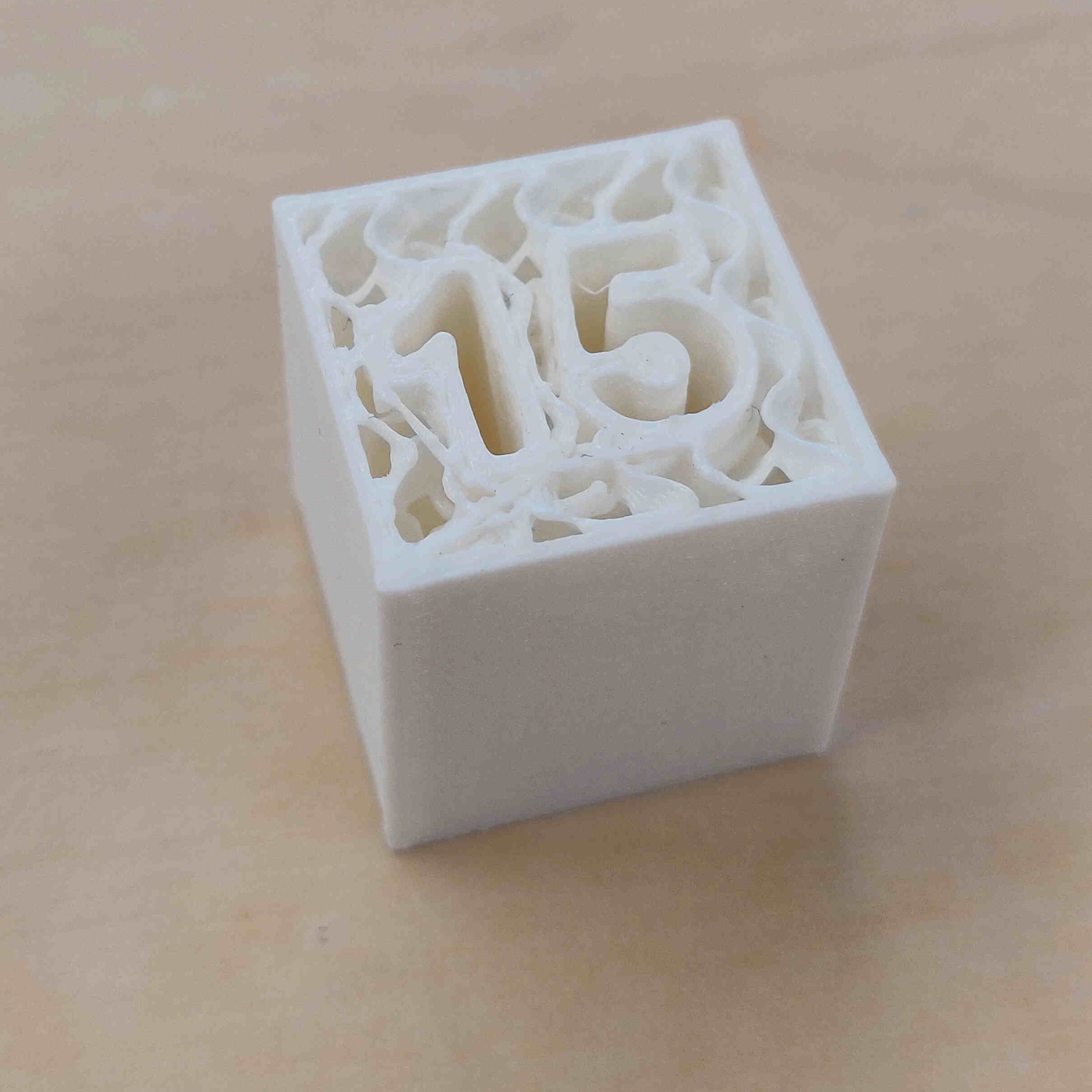
Print Test / Design Rules
(Sourced by ChatGPTv.4o, 19th June, 2024)
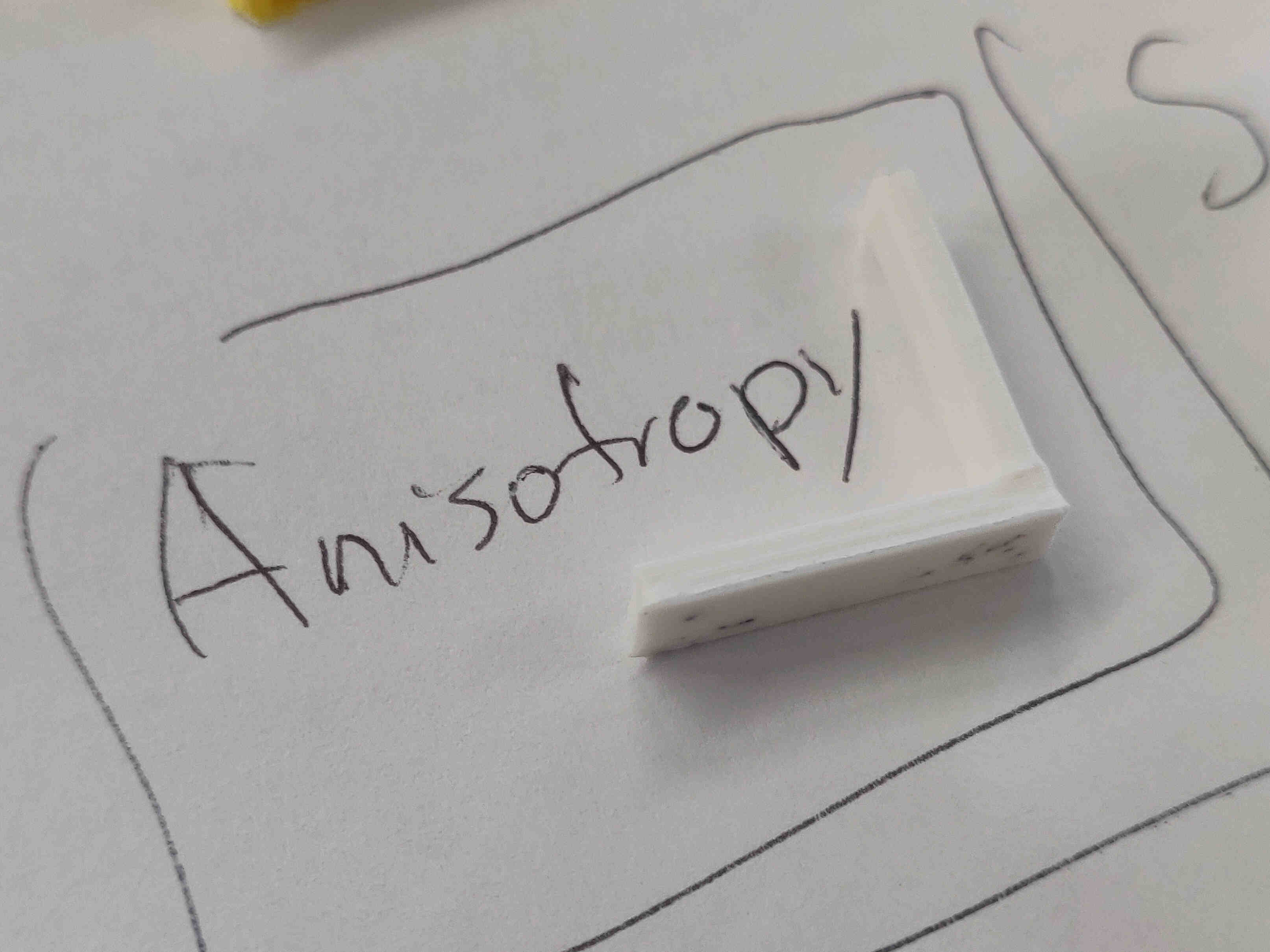
Anisotropy
Anisotropy in 3D printing refers to the directional dependence of a material's properties, meaning that the mechanical properties (like strength, stiffness, and durability) vary depending on the direction in which they are measured. In the context of 3D printing, this often occurs because the printing process involves layer-by-layer deposition of material.By addressing anisotropy, designers can better predict and enhance the performance of 3D printed components for various applications.
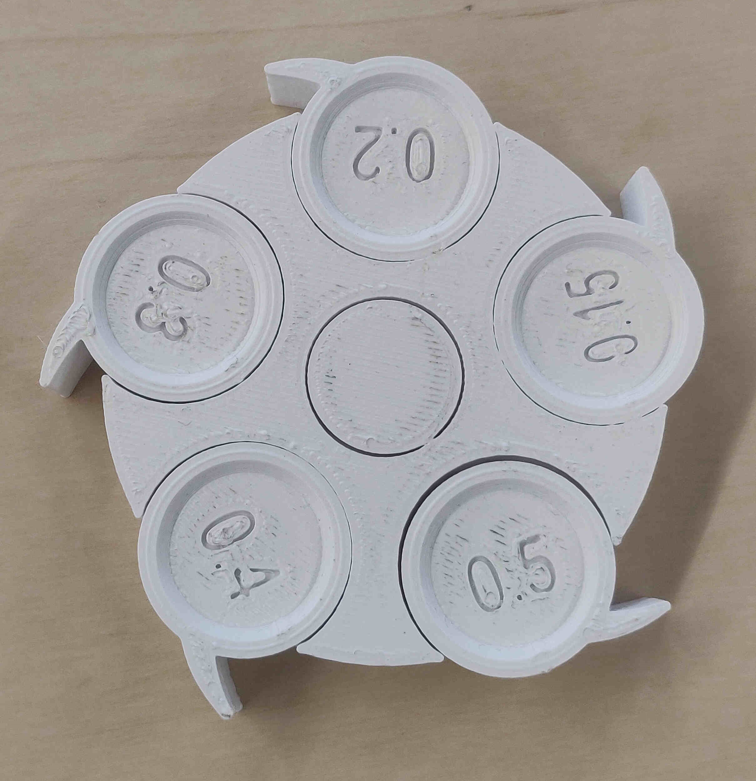
Infill
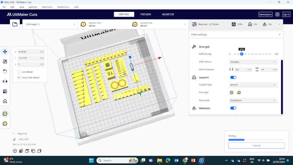
"Infill" refers to the internal structure or pattern used to fill the inside of a printed object. While the outer shell (or perimeter) of the object is printed solid, the interior can be printed with various patterns and densities to balance strength, weight, and material usage.Infill density is typically expressed as a percentage, with 0% being completely hollow and 100% being completely solid. Common infill patterns include grid, honeycomb, and gyroid, each offering different benefits in terms of strength, print time, and material efficiency. Higher infill densities generally result in stronger but heavier and more material-intensive prints, while lower densities save material and time but may reduce the object's strength.
Choosing the right infill pattern and density is crucial for optimizing the performance and cost-effectiveness of 3D printed parts, especially for applications that require specific mechanical properties.
Dimensions
In 3D printing, "dimensions" refer to the measurements of an object's height (Z-axis), width (X-axis), and depth (Y-axis). These dimensions are essential for ensuring that the printed part fits its intended application and matches the design specifications. They also determine if the object can be produced within the build volume capacity of the chosen 3D printer.Accurate dimensions are crucial for both functional and aesthetic purposes, with higher resolution printers able to produce finer details and more precise measurements. Designers must consider potential material shrinkage or expansion during the printing process and may need to scale their digital models accordingly to achieve the desired physical dimensions.
Supports
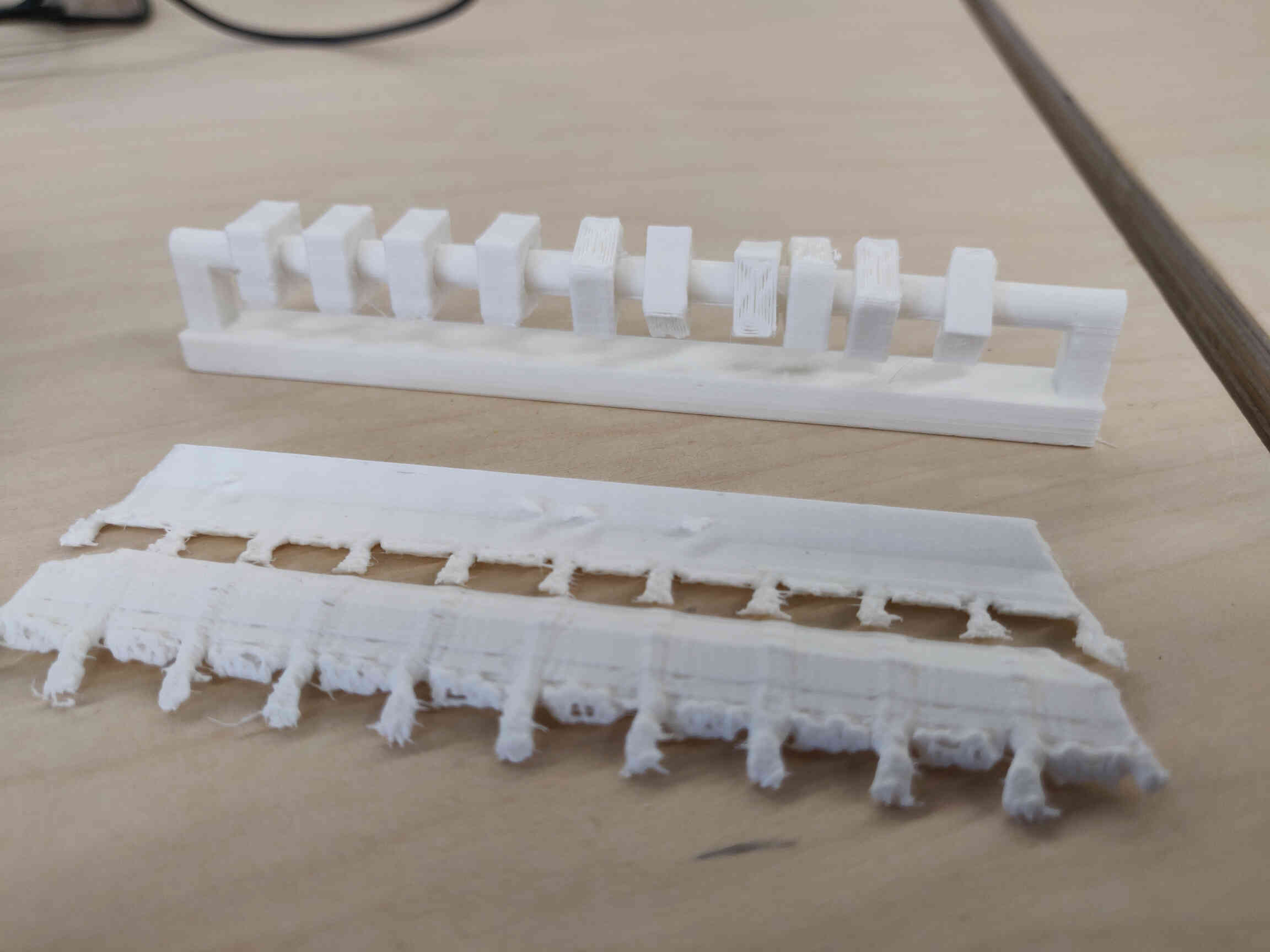
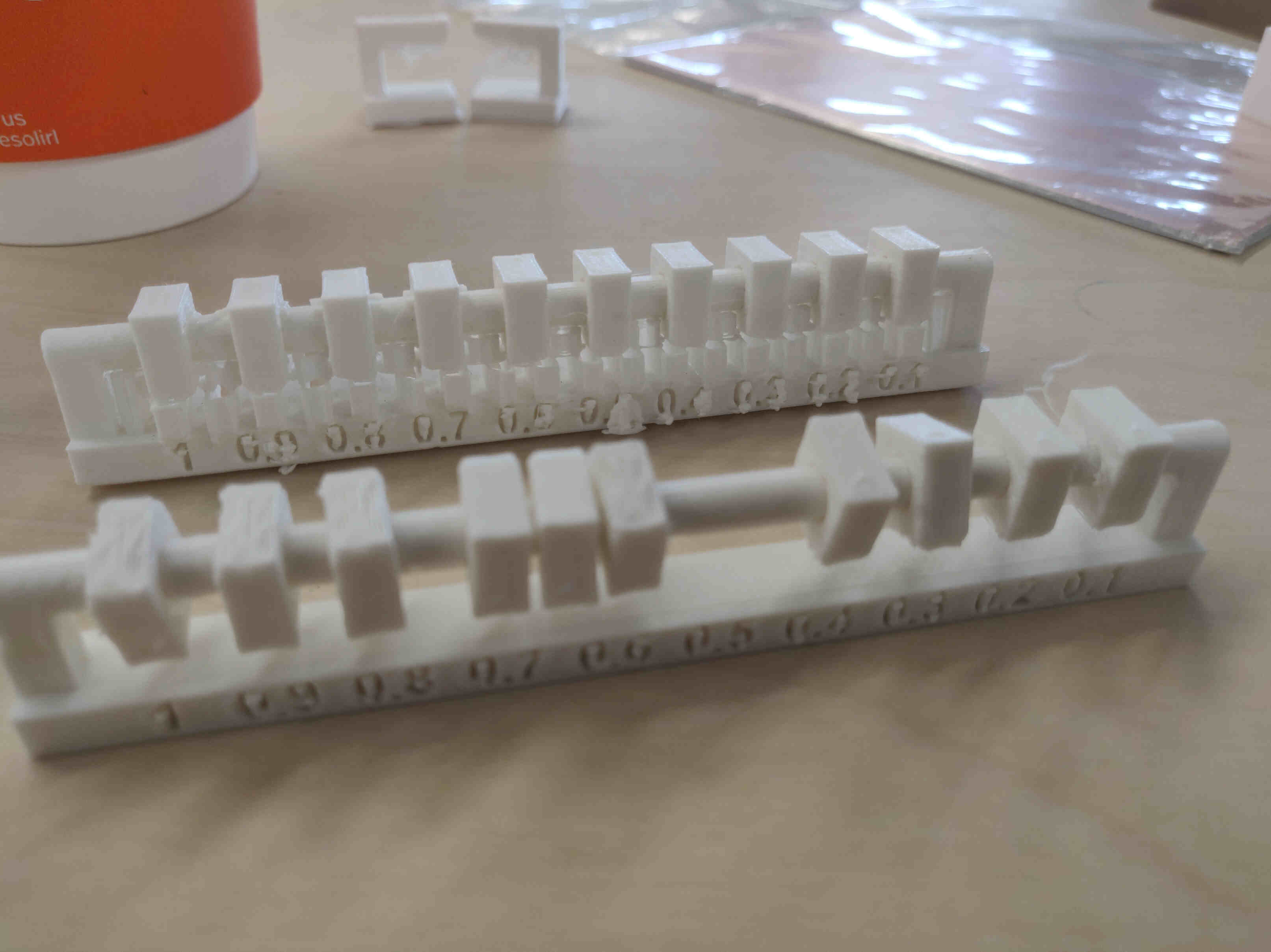
"Supports" refer to temporary structures that provide stability to overhanging or bridging sections of a print.Clearance: "Clearance" refers to the gap or space between the support structures and the actual part of the printed object. This clearance is crucial for ensuring that supports can be removed easily and cleanly after the print is complete.
Proper clearance is important to avoid damaging the printed part during support removal and to ensure a smooth surface finish where the supports were attached. Typically, slicer software allows users to set the clearance distance based on the specific requirements of the print and the type of material being used. Adequate clearance helps achieve a balance between providing sufficient support during printing and facilitating easy removal post-printing.
Overhangs: "Overhangs" refer to portions of the model that extend outward without direct support from below, typically exceeding angles of 45 degrees from the vertical.
Supports are crucial for printing overhangs because they prevent the material from drooping or falling during the layer-by-layer building process. Once the print is complete, these supports are removed, ideally without damaging the main structure of the print. Properly designed supports for overhangs ensure that complex geometries can be accurately and successfully printed.
Unsupported
Angle: In 3D printing, Angles refers to the maximum angle at which a section of a print can extend outward from the vertical axis without needing additional support structures. This angle is typically around 45 degrees, but it can vary depending on the printer, material, and print settings used.Angles exceeding the unsupported angle threshold often require supports to prevent the material from drooping or deforming during the printing process. Understanding and managing the unsupported angle is crucial for optimizing print quality and minimizing the need for post-processing to remove support structures.
Overhang: "Unsupported overhang" refers to a section of the print that extends outward without any support structures underneath it. Overhangs that exceed a certain angle, typically around 45 degrees from the vertical, are considered unsupported and are prone to sagging or deforming during the printing process if not properly managed.
Managing unsupported overhangs is crucial for maintaining print quality. Techniques to handle unsupported overhangs include adjusting the design to reduce overhang angles, using supports during printing, or optimizing print settings such as cooling and print speed to improve the material's ability to bridge gaps. Properly addressing unsupported overhangs ensures the final printed object maintains its intended shape and structural integrity.
Horizontal Bridges: In 3D printing, "unsupported bridges" refer to horizontal sections of a print that span a gap between two supports without any underlying structure. These bridges can sag or deform if the gap is too wide, as there is no material beneath to hold them up during the printing process.
Managing unsupported bridges effectively involves several techniques. Designers can minimize the length of bridges or incorporate intermediate supports within the design. Adjusting printer settings, such as reducing print speed, enhancing cooling, and optimizing layer height, can also help improve the quality of bridged sections. Properly managing unsupported bridges is essential for achieving accurate and structurally sound prints.
Surface Finish
"Surface Finish" refers to the texture and smoothness of the outer surfaces of a printed object. This aspect of a print's quality is influenced by several factors, including the printing technology used, layer height, print speed, and material type.A finer surface finish, with smoother and more detailed surfaces, is typically achieved by using smaller layer heights, which increases the resolution but also extends the print time. The type of 3D printer also plays a significant role; for instance, Stereolithography (SLA) printers generally produce smoother surfaces compared to Fused Deposition Modeling (FDM) printers. Post-processing techniques, such as sanding, polishing, or chemical smoothing, can further enhance the surface finish of a printed object, making it suitable for applications where aesthetics and tactile quality are important.
Wall Thickness
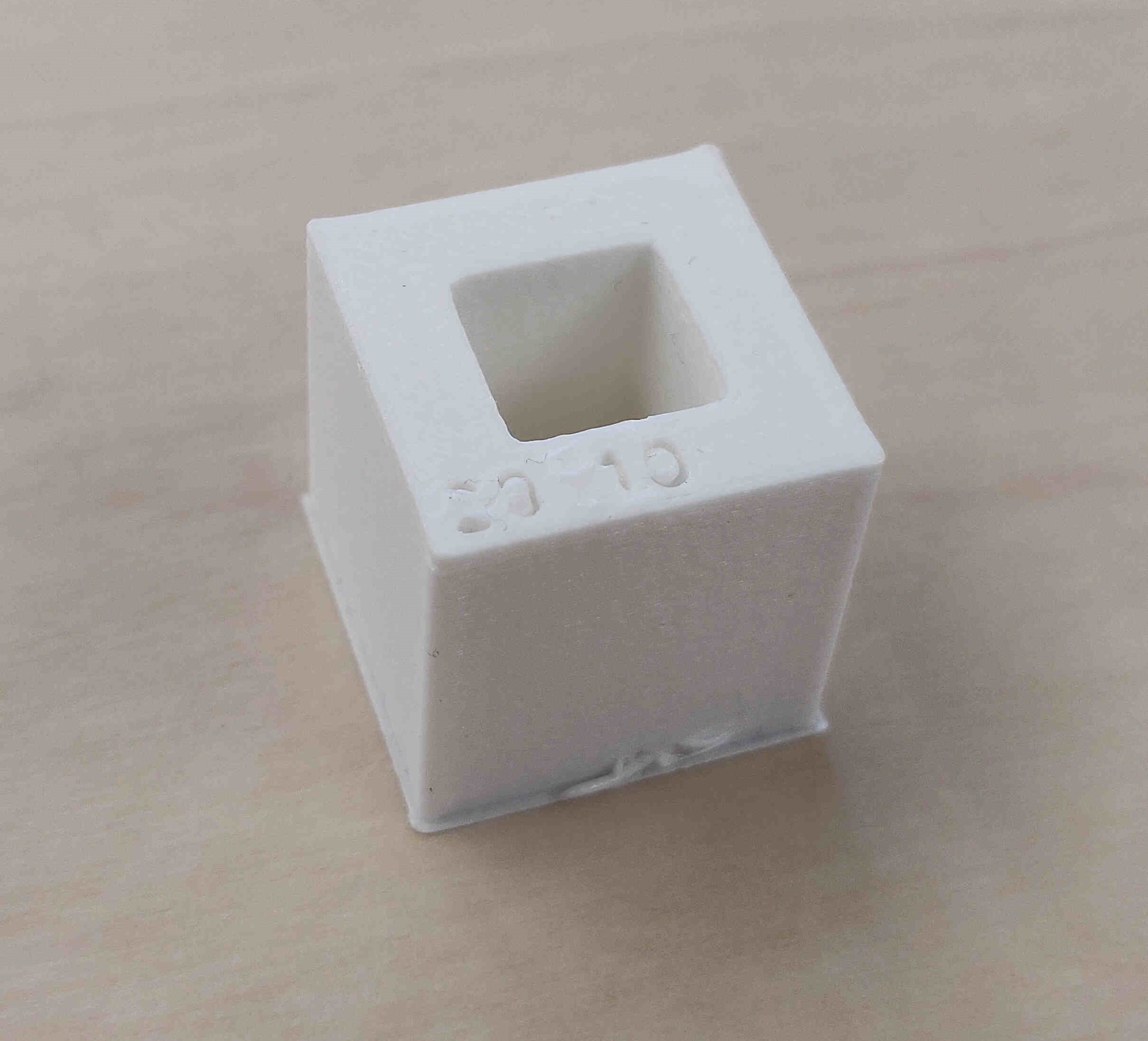
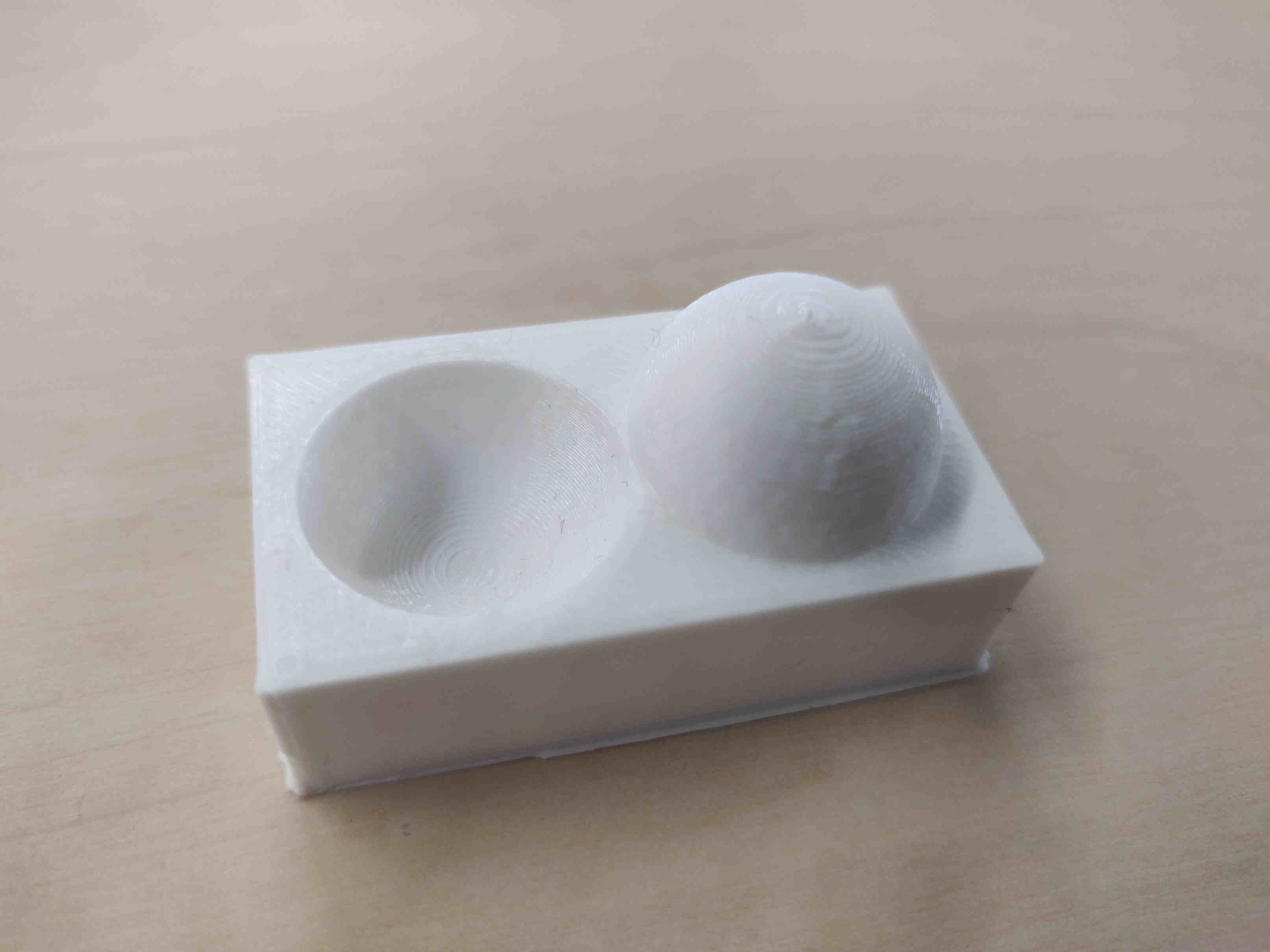
In 3D printing, wall thickness refers to the distance between one surface of your part and its opposite sheer surface.When using your 3D modeling software it is possible to design a surface without a wall thickness, see left picture below. It is important to make sure that that every surface of your 3D file has been assigned a wall thickness because 3D printers need the information about how thick you intend the wall of your object to be.
Minimum wall thickness indicates the lower limit of how thin a wall can be printed in. However, we always recommend to be on the safe side and make the walls a bit thicker.
Besides walls that are too thin, you might also encounter problems with walls that are too thick as well: for materials such as metals, it is especially important to respect maximum wall thicknesses, as thicker sections will generate too much internal stress and could cause the item to crack or even break.
(Wall thickness sourced by Imaterialise)
____________
Individual Assignments:
____________
Wednesday Meeting Reflection
During our meeting we discussed several topics related to this week's project.
ABS, PLA, Resin. Bio-Recyclable. 3D Printing being "not totally safe". The materials can produce toxic fumes.
How to make a 3D print and which may suit me:
Software Process: Meshing -> Slicing (Prusa / Slic3r) -> Printing -> Sharing.
3 Processes: FDM (PLA), SLA (Resin), SLS (Powder).
Laser Scanners: - PolyCAM & Scanniverse (phone), Matterport, Arctic Leon (Best in-house.)
Machines: Prusa, Bambu, Ultimaker, Formlabs, Elegoo.
Files: STL, OBJ. (STL files could be large, so may need to upload through another site).
Research: Print the Legend - Available on Netflix
Make Tests - Download files from FabAcademy.
Test / Document ‘Infill’ - (the amount of inside supports).
- Links to relevant sites:
3DMasters.com
Stratasys.com - Polyjet - highest resolution prints. They owned the intellectual property of 3D Printing originally, until they had to release it and everyone started developing commercial 3D Prints from there.
www.klipper3d.org - 3D-Printer Software.
____________
MY GOALS FOR THIS WEEK:
Attempt to fix any issues in those 3D scans via Blender and then slice & print the result.
Research various in-house 3D Printers and their slicer applications.
Create a non-subtractable 3D design in Blender and print it on the PrusaSlicer.
Global Open Time
Explained my process into 3D scanning and printing in the past week. Adrian also pointed out an extremely useful tip for when I print my non-subtractable 3D Design. Showing that automatically placed supports can overwhelm your design and possibly damage it. So to fix this issue, you can got into the 'Expert' tab in PrusaSlicer and very easily draw on your design where you would prefer the supports to be placed.
____________
Description of in-house 3D Printers
(As described by ChatGPT V.3.5, 2024)
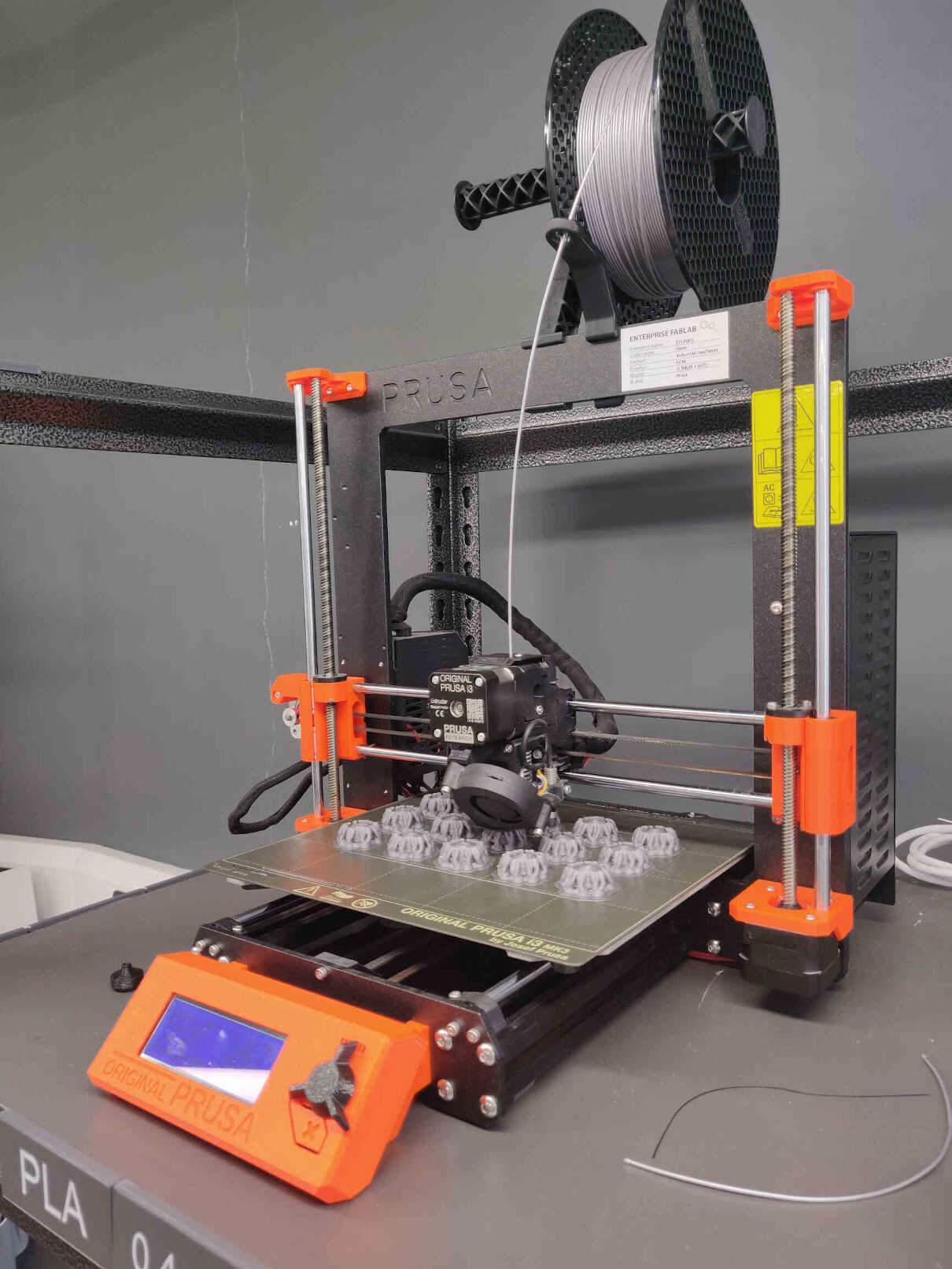
Original Prusa i3 Mk3S Printer: Prusa 3D printers, exemplified by the Prusa i3 series like the MK3, are renowned for their open-source design philosophy, featuring a heated and removable bed, direct drive extruder, automatic bed leveling, and filament sensor to enhance user experience and print quality. The printers, particularly the MK3, integrate features like silent stepper motors and print recovery after power interruptions.
Slicer: PrusaSlicer software is provided for model preparation. With a robust community, continuous updates, and applications ranging from prototyping to small-batch production, Prusa 3D printers are popular choices known for their reliability and innovative features within the 3D printing community.
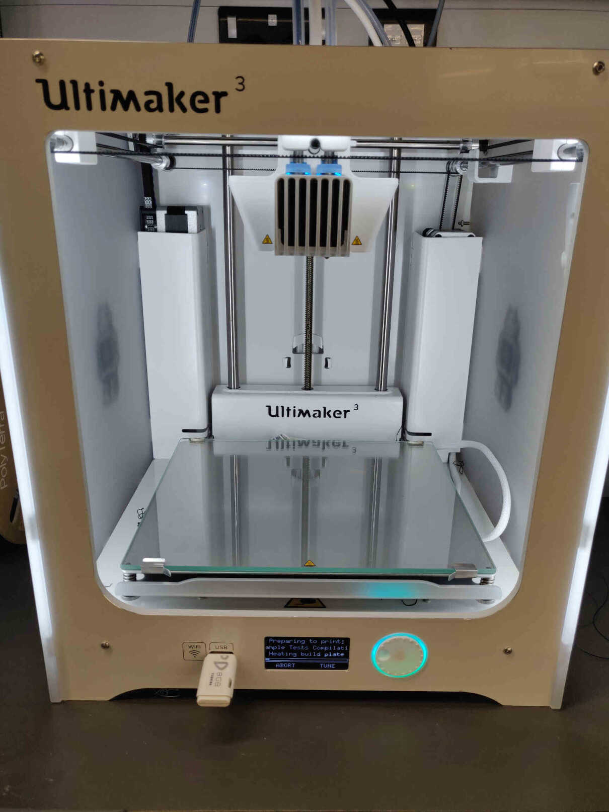
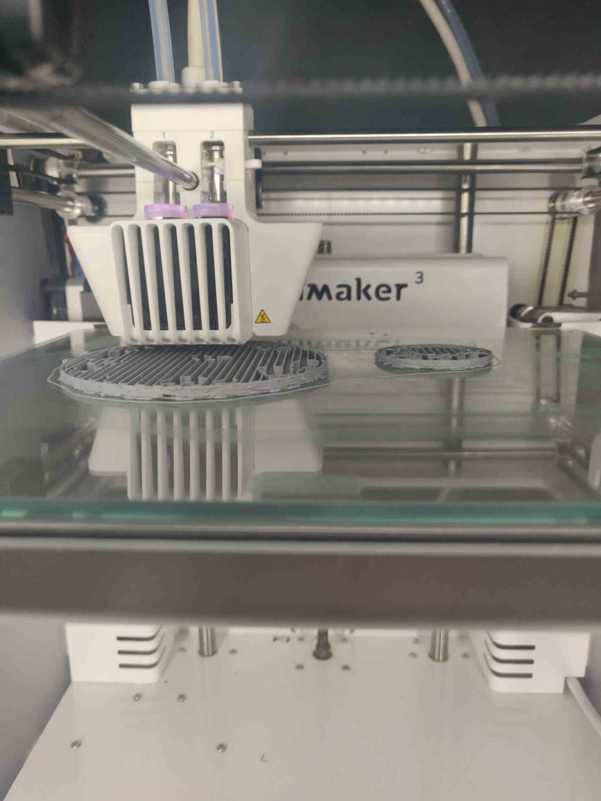
Ultimaker3 Printer: Ultimaker 3D printers, exemplified by models like the Ultimaker 3, are recognized for their reliability and user-friendly design. Featuring Fused Deposition Modeling (FDM) technology, these printers allow users to create three-dimensional objects layer by layer using a variety of materials, including plastics, metals, and ceramics. The Ultimaker 3 is noteworthy for its dual extrusion system, enabling simultaneous printing with two different materials or colors. The open material system allows compatibility with third-party filaments, offering flexibility for diverse applications. With an enclosed build chamber for temperature stability, Ultimaker printers produce high-quality prints with fine details. The printers are often utilized across industries for rapid prototyping, customization, and small-batch production.
Slicer: Ultimaker provides Cura slicing software for model preparation, and their active community and customer support contribute to the printers' popularity in the 3D printing landscape.


Formlabs Printer: Formlabs is a leading provider of professional-grade 3D printers, prominently featuring the Form 3 and Form 3L models, employing stereolithography (SLA) technology for high-precision printing. Known for their detailed and accurate prints, Formlabs printers utilize proprietary resins tailored for various applications. With automated features such as resin cartridge management and additional post-processing accessories like Form Wash and Form Cure, these printers offer a streamlined 3D printing experience. Widely used in industries such as product design, engineering, healthcare, and education, Formlabs products are recognized for their versatility and quality. For the latest details, it's advisable to refer to Formlabs' most recent product information.
Slicer: Formlabs provides PreForm as their proprietary slicing software for preparing 3D models for printing on their SLA 3D printers, including the Form 3 and Form 3L. PreForm allows users to import, orient, and generate the necessary support structures for their 3D models. It plays a crucial role in translating digital designs into the specific instructions (G-code) needed by the Formlabs printers. The software includes features for optimizing print settings, managing print queues, and monitoring the printing process.
____________
Test Examples and Review of Printing Tech
"The Great Blob of Death"

I had decided to test out Ultimaker by printing out a few of those Test Examples for the Group Assignment this week. However I made a fatal error as I wanted to print in PLA but forgot to change the filament from ABS to PLA. Ignoring the warning message from the Ultimaker, because I didn't realise what 'ABS' was at the time, I had it continue the print overnight. I came back the next day to find the technician working on the Ultimaker machine. Because of my error in judgement, the Ultimaker's bed heating settings were too low and the nozzle was clogged with ABS filament but continued to print - forming what the technician called "A Blob of Death". ABS filament basically encased itself around the nozzle wires and fried the circuits. Once forcefully removed, it took several of the nozzle wires with it.
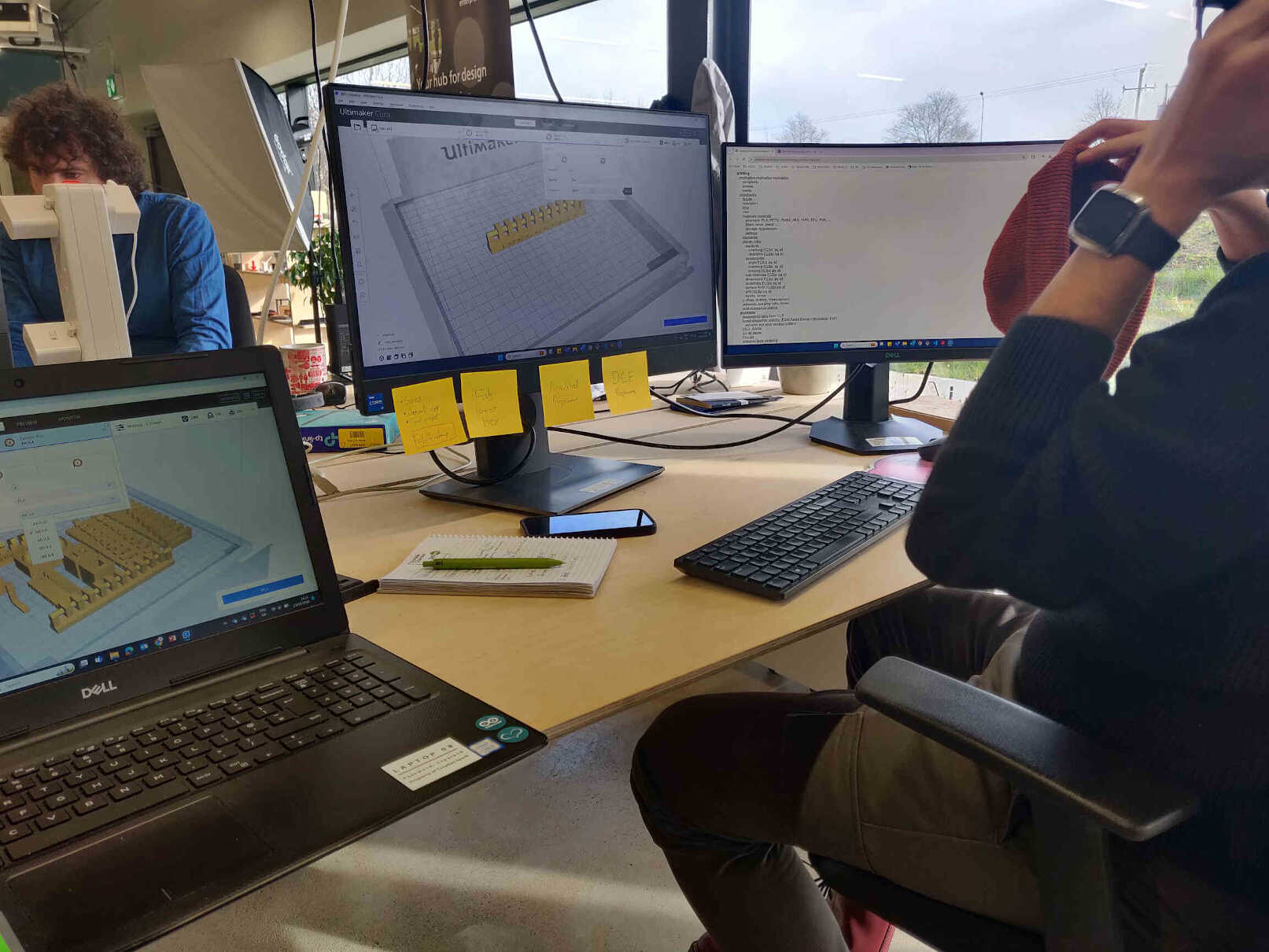
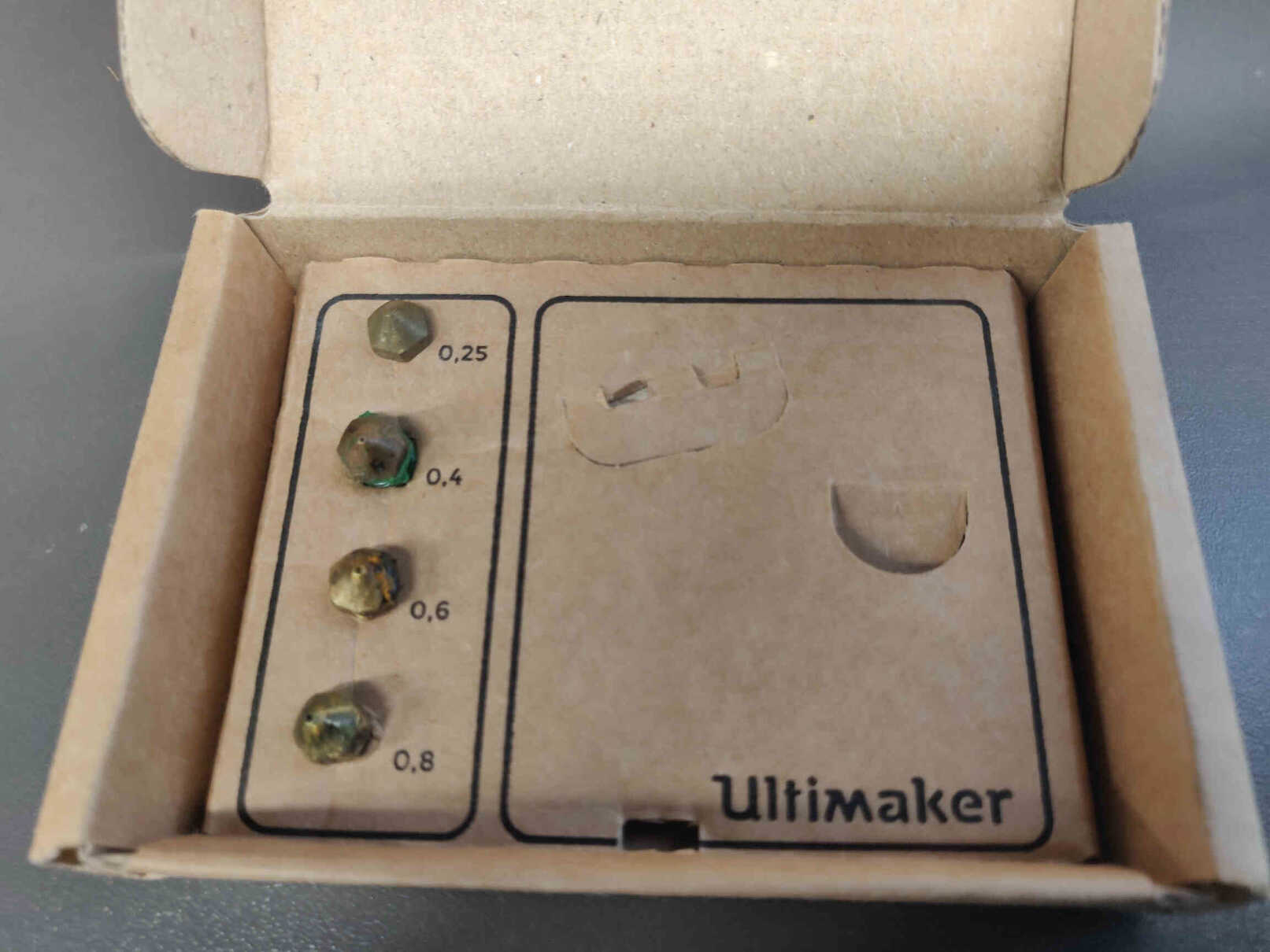
Because of this error, my instructor Oscar gave me a crash course in the Cura 3D Slicing software, and examination of our 3D Printers and their nozzles, as well as a showing me test examples of clearances and tolerances.
____________
3D Printing
(As described by ChatGPT V.3.5, 2024)
3D printing, also known as 'additive manufacturing', is a revolutionary technology that enables the creation of three-dimensional objects layer by layer from digital models. This process contrasts with traditional manufacturing methods, which often involve subtracting material through machining or molding.
Types of 3D Printing Technologies
____________
3D Scanners
(As described by ChatGPT V.3.5, 2024)
3D scanners are devices that capture the physical characteristics of objects, generating digital 3D models for various applications. Utilizing technologies like laser scanning and structured light scanning, these devices come in handheld or fixed configurations. Handheld scanners offer portability for capturing intricate shapes, while fixed scanners provide precision for smaller objects. Widely used in manufacturing, healthcare, design, and archaeology, 3D scanners play roles in reverse engineering, quality control, medical modeling, and artifact preservation. Post-processing software refines scan data, addressing challenges like reflective surfaces. The scanners vary in accuracy and resolution based on technology, with ongoing advancements enhancing speed, accuracy, and versatility in diverse industries.
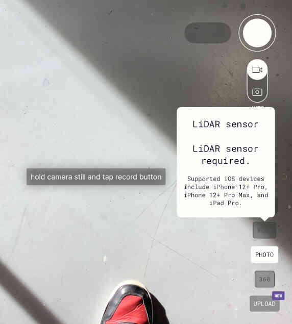
3D Scanners and apps capture detail significantly better if the hardware device you’re using has LIDAR sensors installed. LIDAR, or Light Detection and Ranging, is a remote sensing technology that uses laser light to measure distances and create detailed 3D maps of the environment. Lidar scanners emit laser pulses and measure the time it takes for the light to return after hitting an object. By collecting these distance measurements, Lidar produces precise 3D point clouds, enabling the creation of highly accurate and detailed maps or models. Lidar technology is widely used in various applications, including autonomous vehicles for navigation, forestry for mapping terrain, surveying for topographical mapping, and urban planning for infrastructure development. The versatility and accuracy of Lidar make it a key technology in fields where detailed spatial information is crucial for decision-making and analysis.
____________
Testing 3D Scanning Technology
SCANNERVERSE
The first 3D scanning app I tried out was SCANNERVERSE. This app was recommended by a local colleague who is very experienced in 3D scanning technology. Mostly due to the app being free to download and highly accessible despite it’s solid quality and performance. With the only cost of entry being the cost of an iPad. Thankfully I have - though it’s an older model that doesn’t support LIDAR technology, so my 3D scans would end up being more-so ‘passable’ than ‘impressive’.
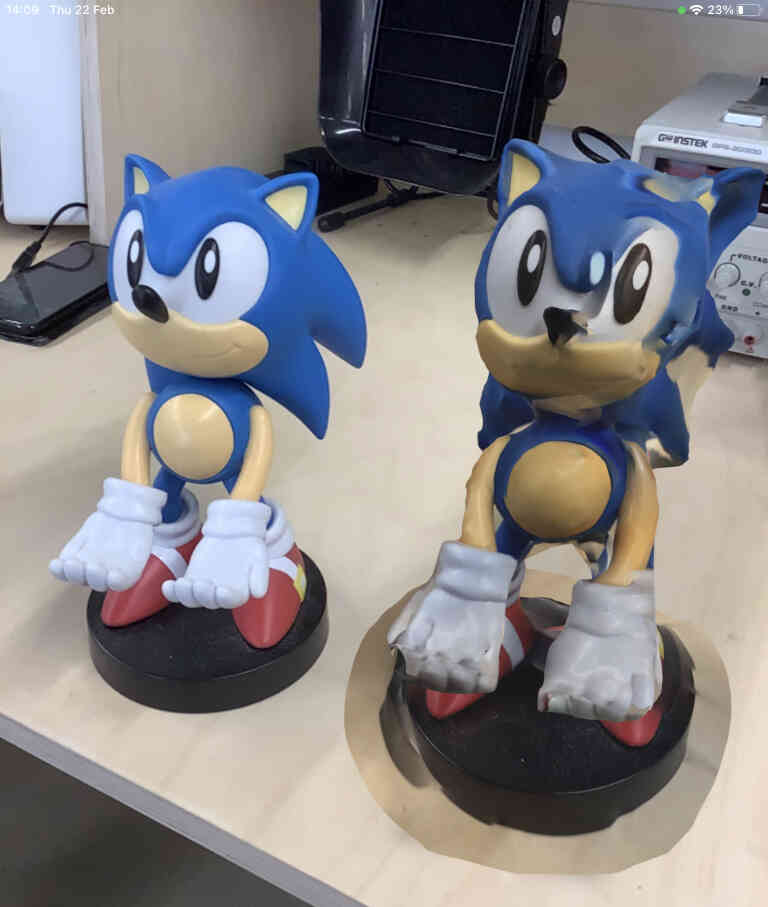
I scanned a Sonic Phone Holder statue that I had lying around to see If I could get a decent enough scan that the statue could be replicated. Though I decided against printing it in favour of a more detailed statue, Sonic was a great object to practice scanning on as it was a recognisable character with overhanging edges and solid structure.
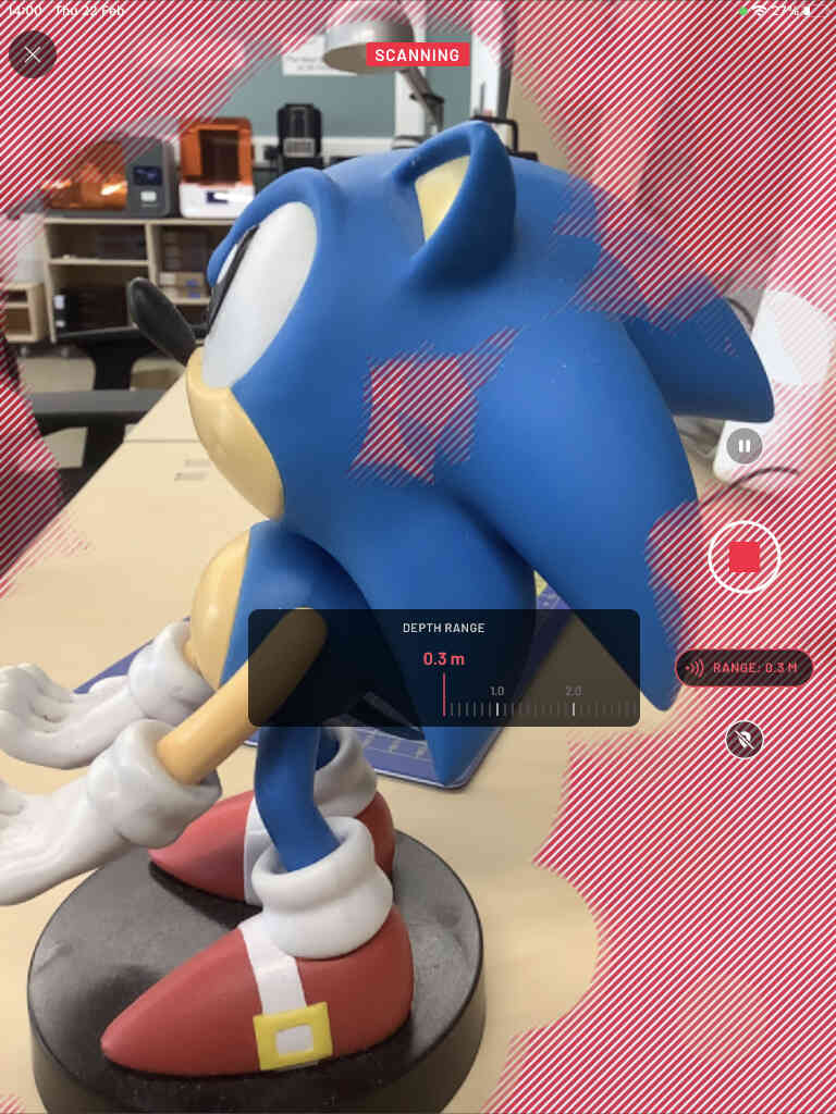
To scan using Scannerverse, you simply measure the distance of the scanning tool (measured in meters). The scanning distance is important to set as measuring too far can lead to the scanner being overwhelmed or confused by unnecessary details around the room, and measuring too close can lead to difficulties in understanding the proportions of the object. Once you are happy with the measuring distance, then you hit the big red ‘record’ button to start the scan, and press it again to end it. It will also ask the size of the object you are trying to scan.


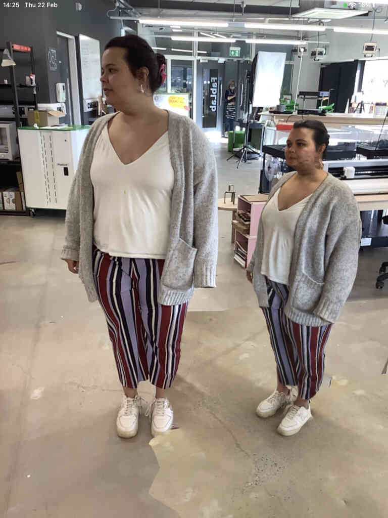
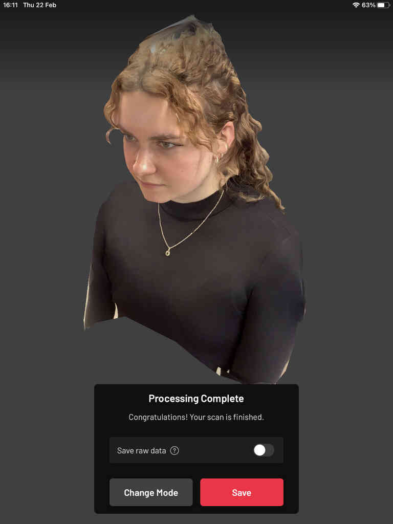
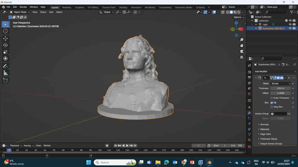
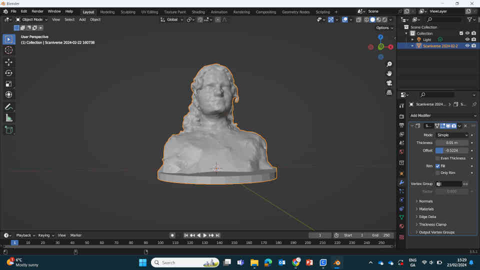
To scan the object you need to hold the camera close enough to the object and keep the camera steady as you walk around the object, capturing the full object in 360 degrees. It’s also important to remember to scan above and under the object, capturing all the sides and crevices. Failure to do so can lead to scans with holes in the objects or having the processor stitching the missing pieces together in very low detail as you can see with my Sonic and ‘Pavola’ human capture. The screen will be full of red lines but will clear up whenever the scanned sides of the object are recognized. Device performance and room lighting play a major part capturing the detail of objects.


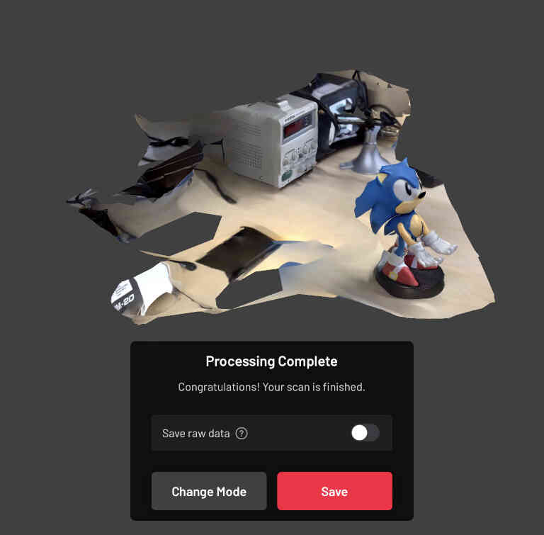
Once you finish your scanning, it appears as a bunch of dots scattered across the screen as a way for the device to understand the real world. Think of it like binary - the scan is in a language that the computer can understand and is processed into an image that humans can understand or relate to.
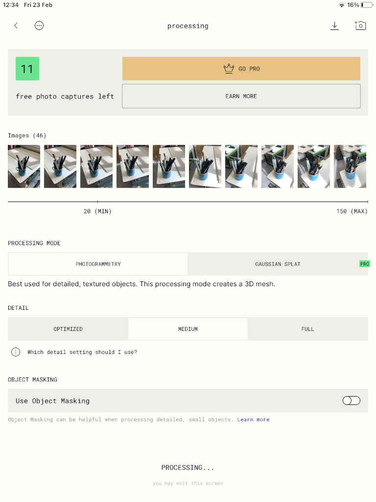
I chose ‘Detail’ processing and just had to wait around 30 seconds for a processed 3D image. The bigger the capture, the longer it will take to process. 3D scanning the printing bed in the print studio took around 5 minutes to process.
With the Sonic figurine processed, I was able to rotate and scale by pinching two fingers on the screen to get a good look at it. Because my measurements were too far, I captured some of the table and tools around the figurine. This was cool to see but awkward in case I needed to isolate the object for viewing or 3D printing. Thankfully there is a handy option to crop the scan from all angles (using a rectangular or circular tool).

I cropped the scan to isolate the statue. My first scan was pretty messy and amateurish, especially because I didn’t position the statue to allow a full 360 scan and also had difficulty scanning below the object, so the overhanging hair was stitched together and looked terrible.
Another really cool option in Scannerverse lets you place and position your object using Augmented Reality (AR View) and so I placed the 3D scanned sonic next to the ‘real’ Sonic as a brilliant way to get a true comparison. I also did this with a human scan later on.
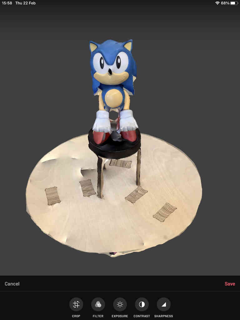
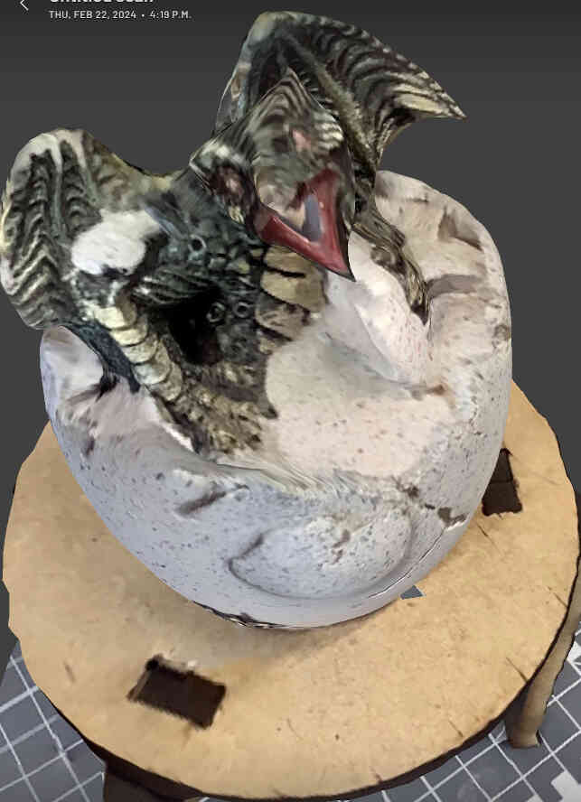
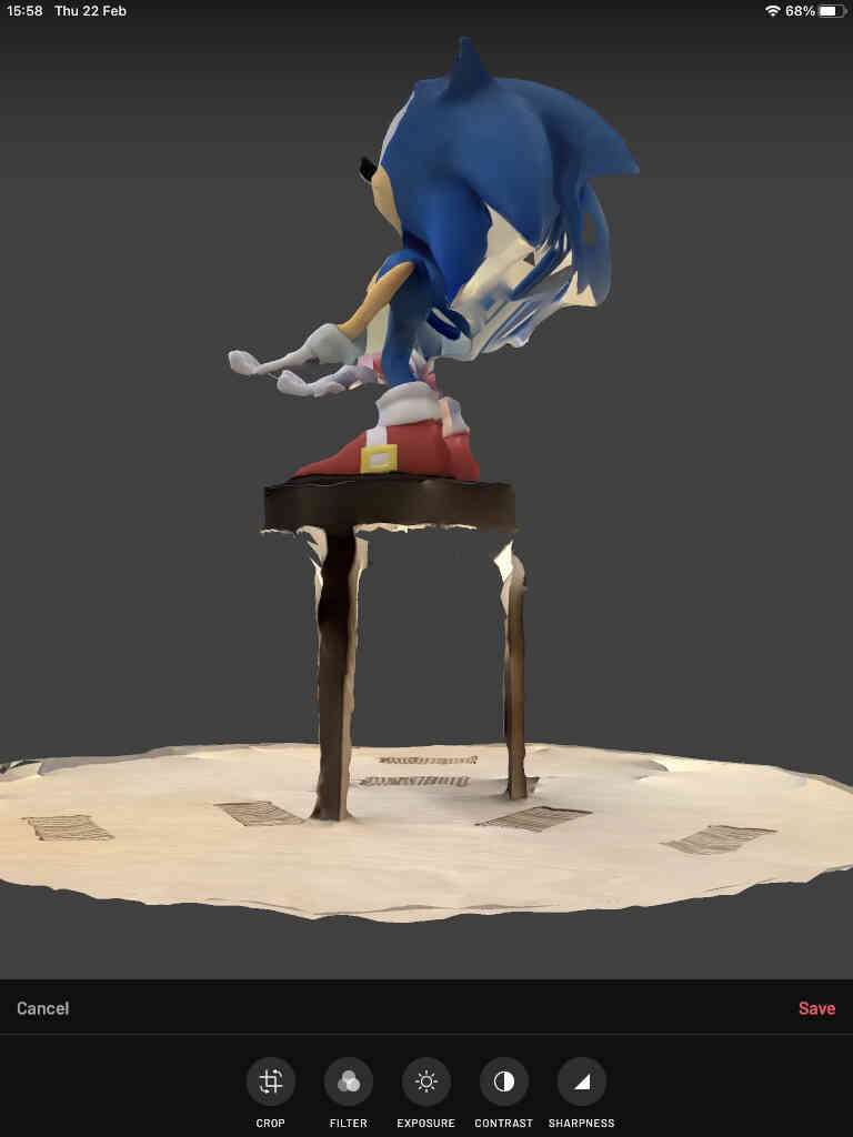
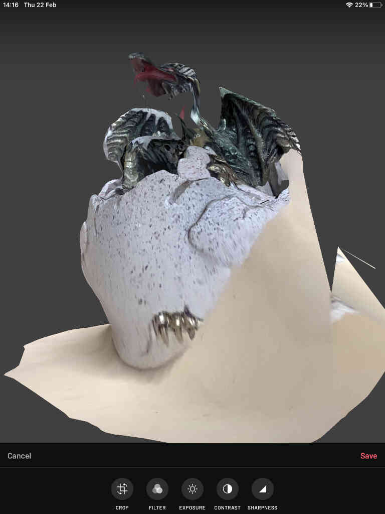
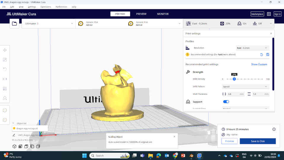
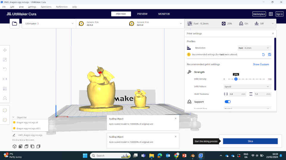
I attempted a more detailed scan using a small Dragon Egg holder/figure and thought of ways I could improve the quality of the scan. Our local Technician recommended placing brightly coloured objects around the object’s location. This would allow the camera scanner to recognise the distance and space from other objects rather than seeing the grey floor and estimating the distance itself. This alone was quite the improvement when I scanned sonic for a second time. I also placed the sonic statue on 2 identical chairs crafted by another local artisan and it made a pretty solid podium for my scanned objects. Scannerverse also allows you to Export your model as an STL File, OBJ, FBX, etc which allows you to import them into game engines, animations and 3D prints.
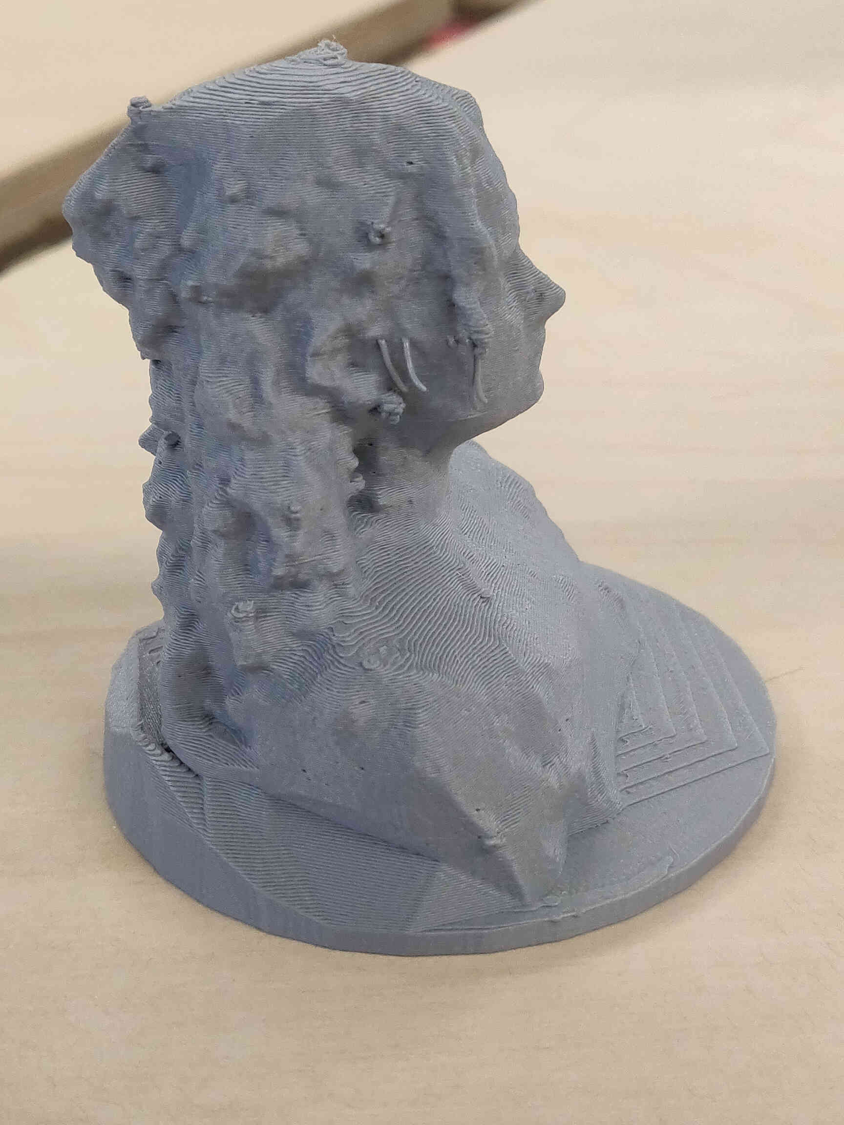
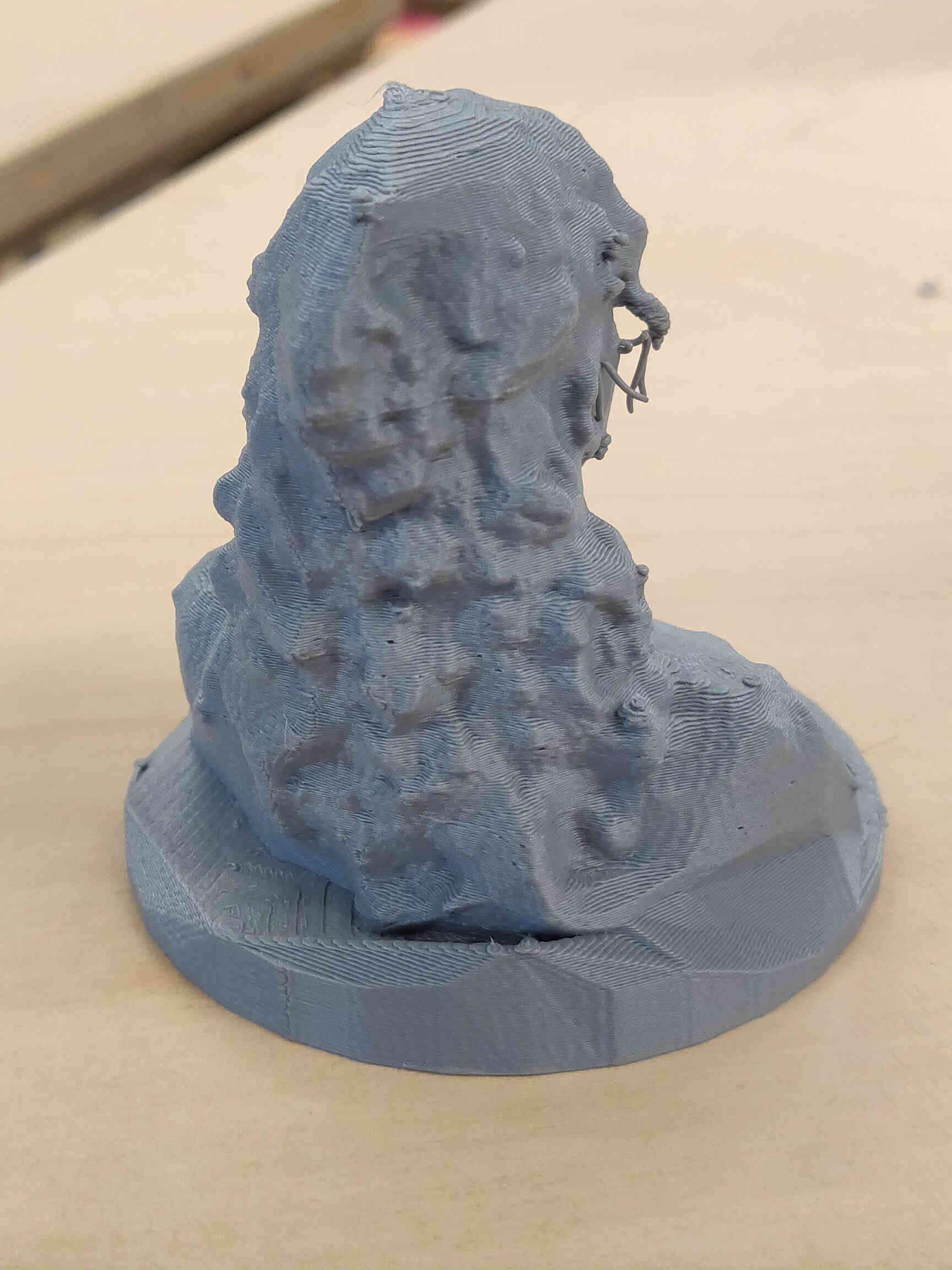
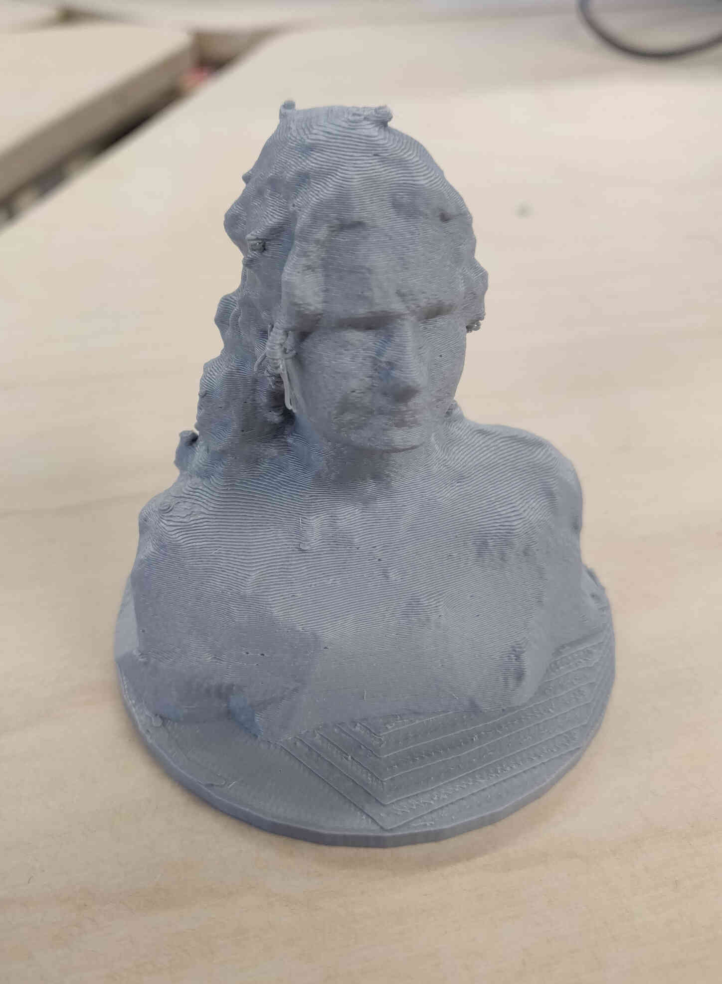
The detail of the scanned Dragon Egg came out beautifully, though for one reason or another it’s head had the quality of a 90’s Playstation 1 game. Still though, I was happy enough to try printing the dragon egg, as well as a human scan that we named ‘Pavola’.

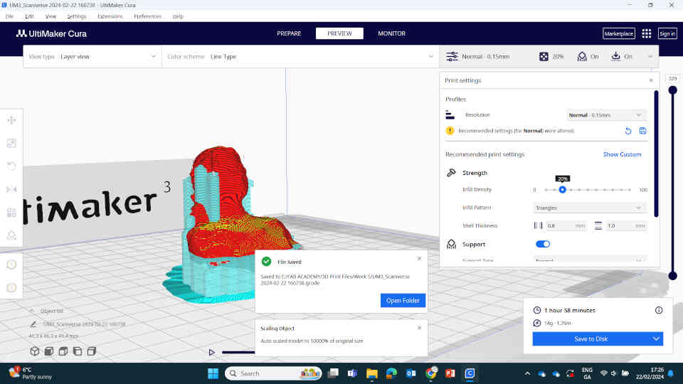
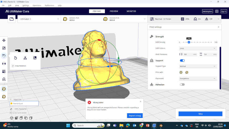
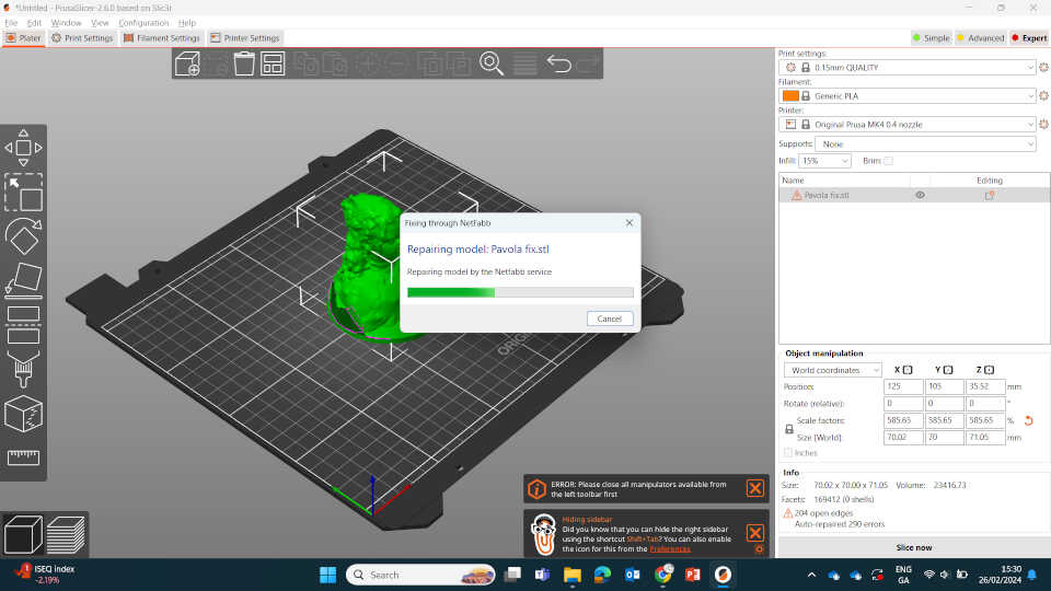
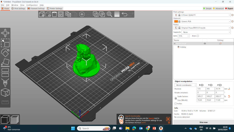
My first couple prints of the Dragon Egg came out quite poorly as it wasn’t watertight. Normally I would just hit the ‘Repair using NETTFAB’ feature in PrusaSlicer but as I was attempting to explore Ultimaker Printers, I noticed that this feature was missing. Turns out that Cura DOES have it, but only as a paid add-on - which I had no intention of purchasing as I much rather print off of the Prusa Printers. However I was determined to get the Pavola printed through Ultimaker, so I brought the STL file into Prusaslicer and repaired it from there -> then saved as an STL file and brought it into Cura to slice it from there. This worked perfectly well and produced a decent quality PLA print which you can see here.
____________
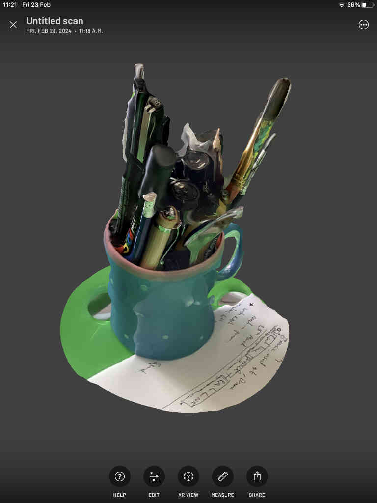
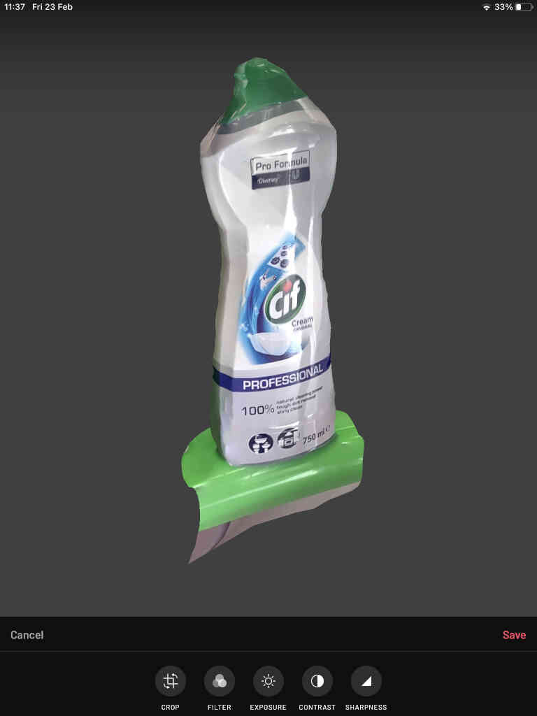
Scanning Nearby Utensils
Scanning small objects like the 'Cif' bottle worked out quite well, but more clustered objects like a cup full of pens start to mold into one object - still pretty decent for a free app! Tried scanning full printing bed but to no avail - the sun was shining down hard at this particular time, but results in a 3D scan that looks like a printing bed set on fire weeks ago!

Scanned a Marshall amplifier and though the detail up close is hit-or-miss, it is remarkable how real it looks (from afar) after such a quick and easy scan. (Don't look under the chair though!)


____________
POLYCAM
The Enterprise Fablab technician recommended PolyCAM to me, as it was a high quality 3D scanner that was also available for free on the iPad with a few extra tools and features to improve your scan. It did have a few drawbacks though, including paid restrictions that I will mention shortly. Working very similarly at first to Scannerverse, you just measure your scanning distance and hit record.

Immediately after hitting Record, you’ll notice the first major difference between PolyCAM and Scannerverse. When capturing the 3D space, PolyCAM doesn’t show any red lines or indication on what space has been captured. Instead, PolyCAM takes pictures instead of red lines and limits how many pictures it will take during your scan, (giving an option to pay to extend the limit). Once you finish scanning your object, A lot more manipulation options are available to you after processing but by and large the results with my current hardware and free account lead me to no better results than than the Scannerverse App.


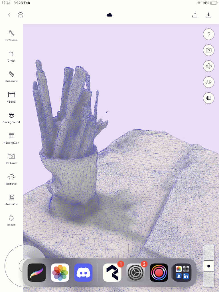
I attempted to scan a cup filled with pens and markers using both scanning apps and it looked more or less the same with similar imperfections using both apps. In the end, the UI & UX Design for Scannerverse is what won me over. Overall I’m uninterested in further continuing my research into PolyCAM - at least for now.
Artec Leo & KIRI
Unfortunately with the previous scans, documentation and printing issues with the scans, I ran out of time to test out the Arctic Leon scanning device or the KIRI browser/phone tool. But I have my eyes on them and intend on using each one soon enough when I’m able.____________
Slicing iPad Scans
Before we can print out a scanned object, we need to ‘slice’ it and get the G-Code file to enable a working print. The slicer application needed depends on the 3D printer you intend on using.
I swear by the Prusa Slicer and Print Machine. It’s allows been super reliable, easy to navigate and allows for model repairing by clicking the danger-icon next to your file name when imported into PrusaSlicer.
____________
Printing my 3D Scans
Printing the 'Dragon Egg' and 'Pavola'

As mentioned earlier, the dragon egg print wasn't watertight and the above shows the result of that. I learned from this print as I worked on the Pavola print and was happy with the improved result.
____________
3D Design Assignment
Creating a non-subtractable design in Blender
For our assignment this week, we need to create a non-subtractable 3D design and then print it. A non-subtractive design basically means a design within a design such as a sphere held inside of another sphere. Where the interior object can’t be removed from the exterior object (excluding forceful removal or breakage). Another example includes an interlocking chain. The idea in printing it is to see if the design is viable in the real world.
As much as I wanted to design a type of chain, I had decided to create a box within a sphere. More specifically, I wanted to create a square box reminiscent of a 6-sided die that would be held within a spherical design you could see through. Creating this design would be simple, needing only the Boolean and Array modifiers housed inside Blender. My goal is moreso to test the structure of this design in the physical world. By doing this, I’d be more comfortable printing more complex designs in the future. So let’s start the tutorial!!!

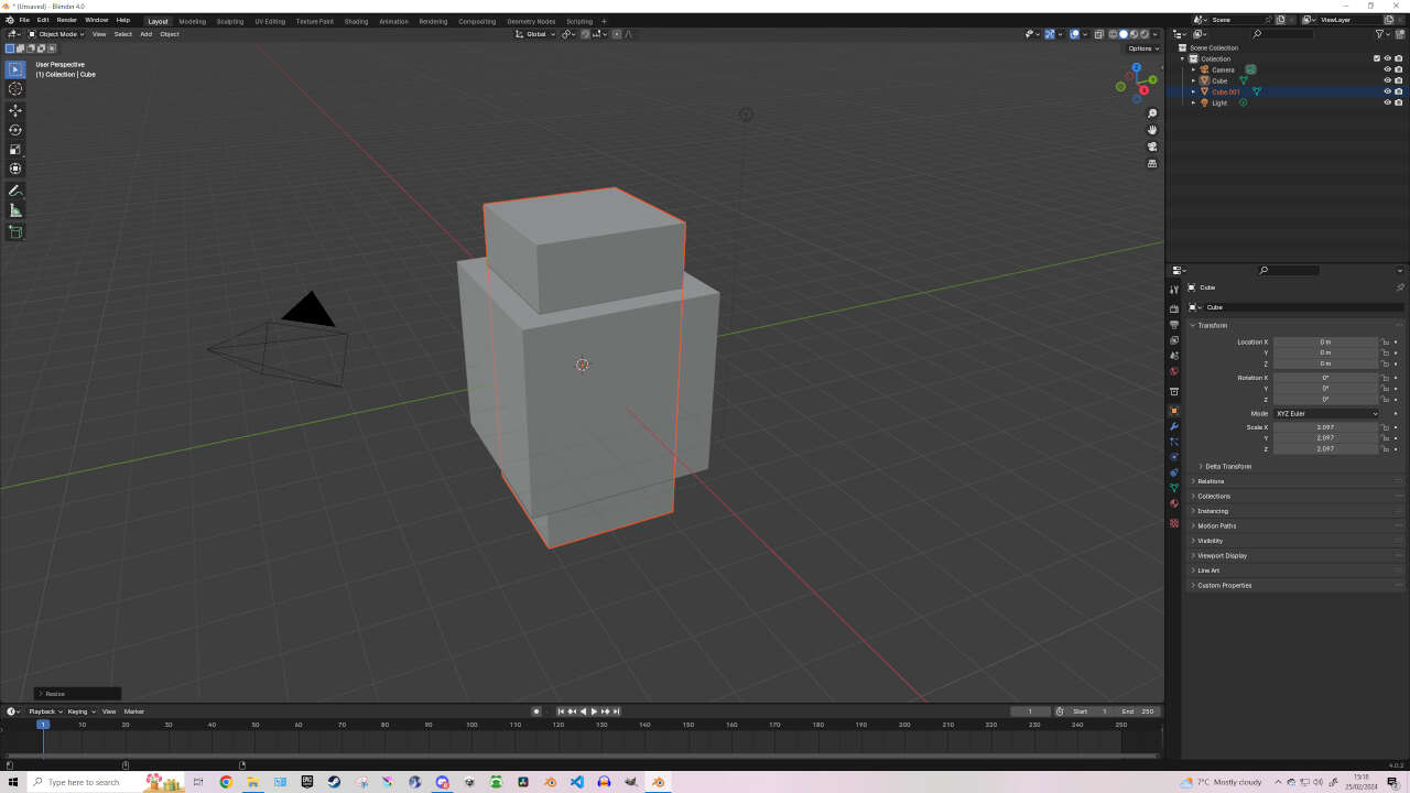
Again, with every good design in Blender, we start with a cube.
Select your cube and Duplicate it into the same position.
You can Duplicate with either SHIFT+D or by using Ctrl+C to copy and then Ctrl+V to paste. Remember these Duplication shortcuts because we will be using them often!
Once that’s done, select one of your cubes (doesn’t matter which) and press S to Scale it. Move the mouse to make it smaller then left-click or press ‘Enter’ to set the scale. With the smaller cube selected, press S, then Z to scale on the Z-axis to make it longer. Press Enter to set the scale.
Now we should have a longer rectangle inside of a cube.
Now we need to repeat this process until all sides of the cube are covered.
- Select the long rectangle and Duplicate it.
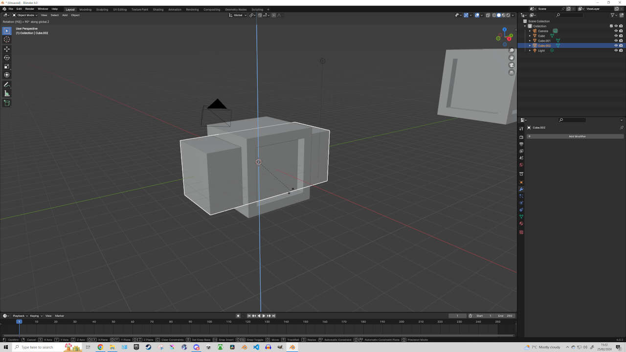
- Select the duplicated rectangle and press R (Rotate), then X (X-axis), then type 90 (turn 90 degrees), then hit Enter.
- Select the vertical long rectangle and Duplicate it again.
- Select the newly duplicated rectangle and press R (Rotate), then Y (Y-axis), then type 90 (turn 90 degrees), then hit Enter.


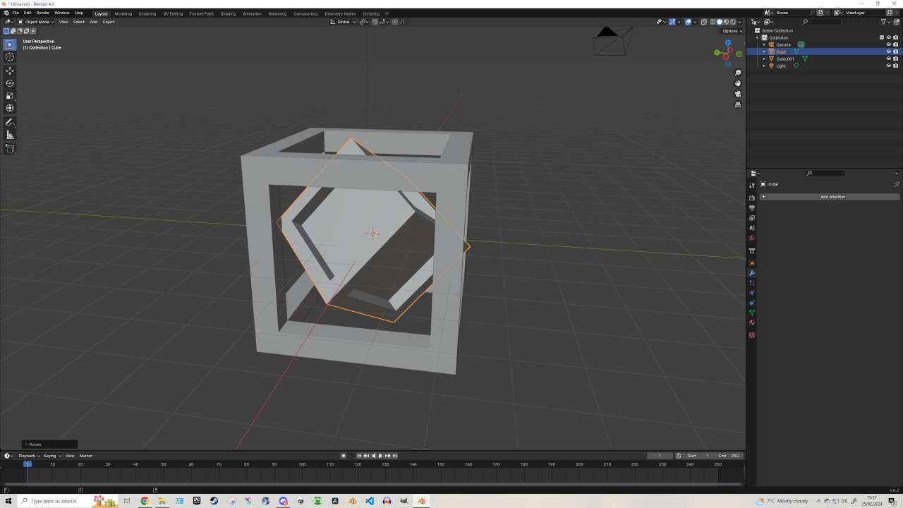
Now we need to Join all the rectangles. Select a rectangle then SHIFT+Select the other rectangles, Right-click and select ‘Join’. This turns all the rectangles into one object, (that we will call a ‘jointed rectangle’ for tutorial purposes), that we can use to hollow out our cube. To do this, we need the ‘Boolean’ modifier.

Select your cube and look for the ‘Modifiers’ tab on the right side of the screen, (It looks like a spanner or wrench). Then click on the ‘Add Modifier’ button. In the search bar in the modifiers tab, type ‘Boolean’ and select the Boolean modifier. With it set to ‘Difference’, click on the icon that looks like a Colour Picker and click on the Jointed Rectangle. Then select ‘Apply’ which can be found in the drop down menu at the top right corner of the boolean modifier - next to the camera icon. When done, you can move and even delete the Jointed Rectangle.


Editor's Note: Now, this didn’t do what I expected it to do originally but we will still use the result. I expected it to hollow out the cube but instead it hollowed out as far as the joints on the jointed rectangle were connected - building walls inside of the cube instead. But like I said, we can use this object to create a six-sided die to be held within a spherical object. We will call this object our ‘die6’ (six-sided die).
Push this to the side for the moment, using G to Grab Object, so that it won’t get in the way of our next design.

Now create a new Cube by Right Clicking in the 3D workspace and select ‘Add -> Mesh -> Cube’.
- Select your cube and Duplicate it into the same position.
- Select one of your cubes (doesn’t matter which) and press S to Scale it. Move the mouse to make it smaller then press ‘Enter’ to set the scale.
- With the smaller cube selected, press S then X to scale on the X-axis to make it longer. Press Enter to set the scale.
Now we should have a longer rectangle inside of a cube like before, albeit pointing in a different direction. This time, we’ll hollow out the cube individually.

Select your cube and look for the ‘Modifiers’ tab on the right side of the screen. In the search bar in the modifiers tab, type ‘Boolean’ and select the Boolean modifier. With it set to ‘Difference’, click on the icon that looks like a Colour Picker and click on the extending Rectangle. Then select ‘Apply’ which can be found in the drop down menu at the top right corner of the boolean modifier - next to the camera icon.
If done correctly, you should be able to move the rectangle with G and see that our cube was hollowed out. If still holding onto the object, Right Click to return it to position.
Now select your rectangle and hit R (Rotate), Z (Z-Axis), 90 (90 degrees), Enter. Select your cube and in the ‘Boolean’ modifier select ‘Apply’ which can be found in the drop down menu at the top right corner of the boolean modifier.

Now once again select your rectangle and hit R (Rotate), X (X-Axis), 90 (90 degrees), Enter. Select your cube and in the ‘Boolean’ modifier select ‘Apply’ which can be found in the drop down menu at the top right corner of the boolean modifier. You should now be able to see your cube hollowed out.
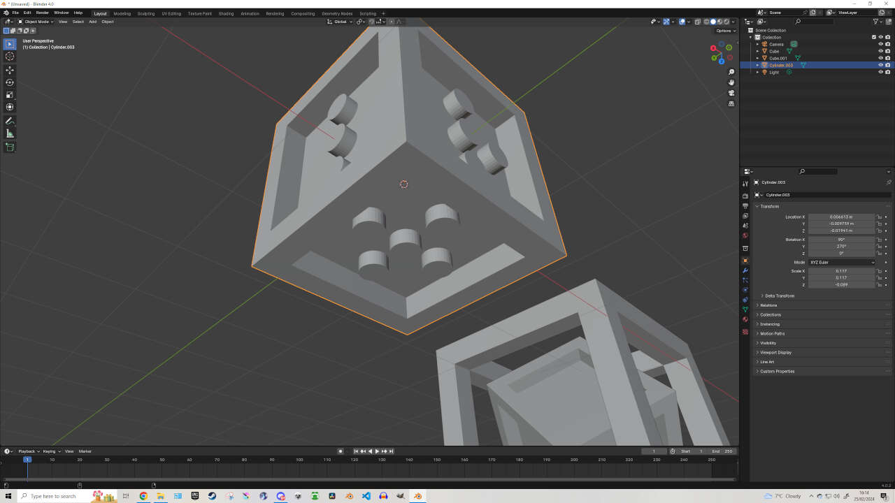
For a bit of visualization, move your ‘die6’ into the hollowed out cube and see if it fits inside and how you would like it to appear when printed. You can scale or transform your die6 to check proportions. When you’re happy with your proportions, we can move onto designing our die6 into a functional six-sided die. First, move your hollowed out design to the left using ‘G’ to Grab Object.
Now return it to the center of the workspace. To do this, select your die6 and click on the ‘Object’ tab on the right hand side (directly above the Modifiers tab). Here you can see the Transform settings for your selected object. We want to return the Location and Rotation back to zero. Do this by clicking on the Transform’s X, Y or Z metrics and hit ‘Backspace’. Do this for all XYZ metrics for Location and Rotation (you can leave Scale alone).
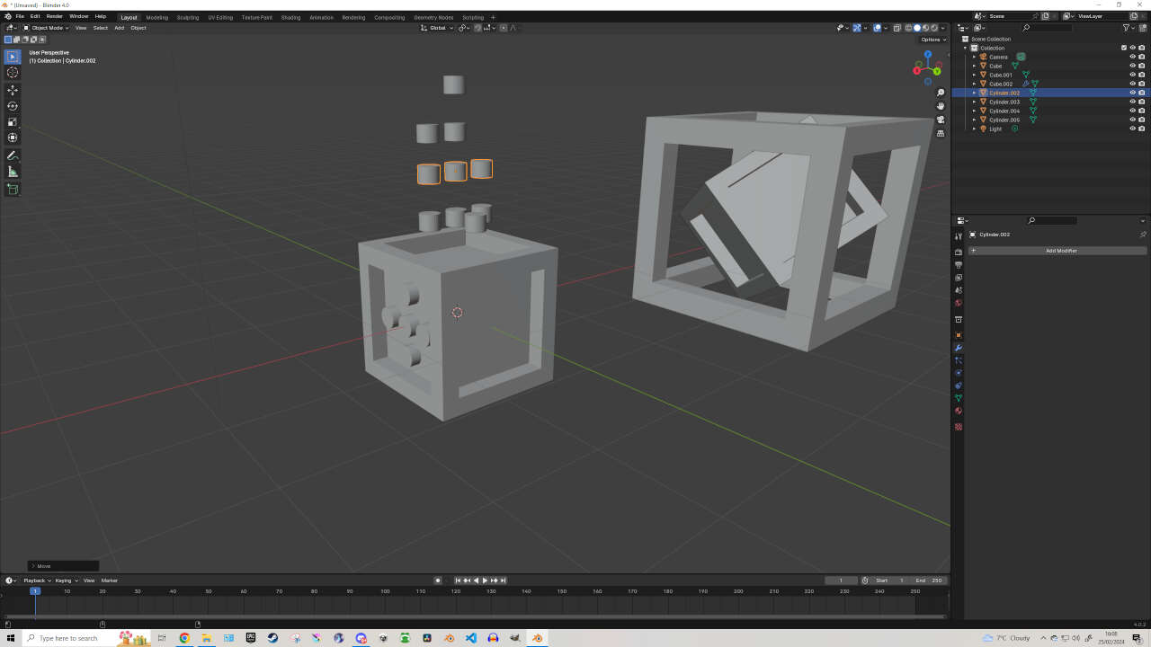
We are now going to add the dots to each side of the die6. To do this, ‘Add -> Mesh -> Cylinder’. Scale your cylinder to represent a dot on the die6 - small, but big enough to be placed in & outside of the die6. I’ll admit, there’s probably a way more effective way of doing this, but this is how I did it…

G (Grab) your new Cylinder, press Z and move it ABOVE the Cube within the Z-axis. SHIFT+D to duplicate 4 times.
To get the measurements correct, click the top Z icon on the Gizmo bar. (Gizmo Bar can be found on the top-right hand corner of the 3D workspace - it’s the Blue, Green and Red icon showing the XYZ axis). This will give you a 2D eagle’s eye view of the workspace and cylinders - which will help you move the cylinders on the X & Y axis without affecting the Z-axis.
Now G (Grab) your cylinders and place them equally spread apart to look similar to a ‘+’ symbol. Once arranged, drag select all 5 cylinders and Right Click -> Join. With all cylinders joined, hit click on the bottom Y-Axis from the Gizmo Bar. This will give you a front 2D view of your Joined Cylinders.

Take your Joined Cylinders by selecting them, then press G, then Z to move them along the Z axis and place them sitting inside of one of the die6’s faces - but just enough so that we can still see them poking out. When satisfied with your positioning, click on the die6 and navigate to the Boolean modifier. If the Boolean modifier has been removed, add it again.
This time instead of being set to ‘Difference’ -> set it to ‘Union’. Then using the Colour Picker icon, select your Joined Cylinders and hit ‘Apply’ from the Boolean modifier. This will have added your cylinder dots to the die6’s shape.
Now with your die6 selected, hit ‘R’ then 90 to rotate the object to one of the other faces.
Editor's Note: Note: If the die6 isn't orienting itself correctly, you may need to Right-Click the rectangle and ‘Set Origin Point -> Origin to Geometry’ before you move anything - however the current shape of the die6 may have affected its Origin point. Experiment with the ‘Set Origin Point’ options to find its center, using the 3D Cursor / Set Origin to 3D Cursor if needed.
Once one of the new blank faces on the die6 has been correctly orientated to be facing the Joined Cylinders upwards, we can move onto the next step.
Select your Joined Cylinders and press ‘Tab’ to enter Edit Mode. Otherwise, you can click on ‘Object Mode’ at the top-left corner of Blender and choose ‘Edit Mode’. While in Edit Mode, Carefully drag select over one of the cylinders and press ‘Backspace’ to delete a cylinder from the Joined Cylinders object. You may need to angle the camera and drag select & backspace a couple times to remove the cylinder shape.
Now return to object mode, click on the die6 and navigate to the Boolean modifier. Keep it set to ‘Union’. Then using the Colour Picker icon, select your Joined Cylinders and hit ‘Apply’ from the Boolean modifier. This will have added your 4 cylinder dots to the die6’s shape.
Repeat the above processes to allow the die6 object to have 5 dots on one face, 4 dots on another face, 3 on another, 2 on another and finally 1 dot on another face - keeping the last face blank. Once all is done, you should have a 6-sided Die that can fit inside the hollowed out box we made.

Editor's Note: I hear you asking - “wait, shouldn’t there be a face with 6 dots? Is this not a 6-sided die? Why did we only make 5 cylinders instead of 6?” You aren’t mistaken, but for this design I decided to screw around and make a ‘Troll Die’, where the blank face remaining on the die6 could be considered as a ‘6’ or a ‘1’, leading to a lot of confusion.. Impractical, I know - but I wanted to make one for fun.
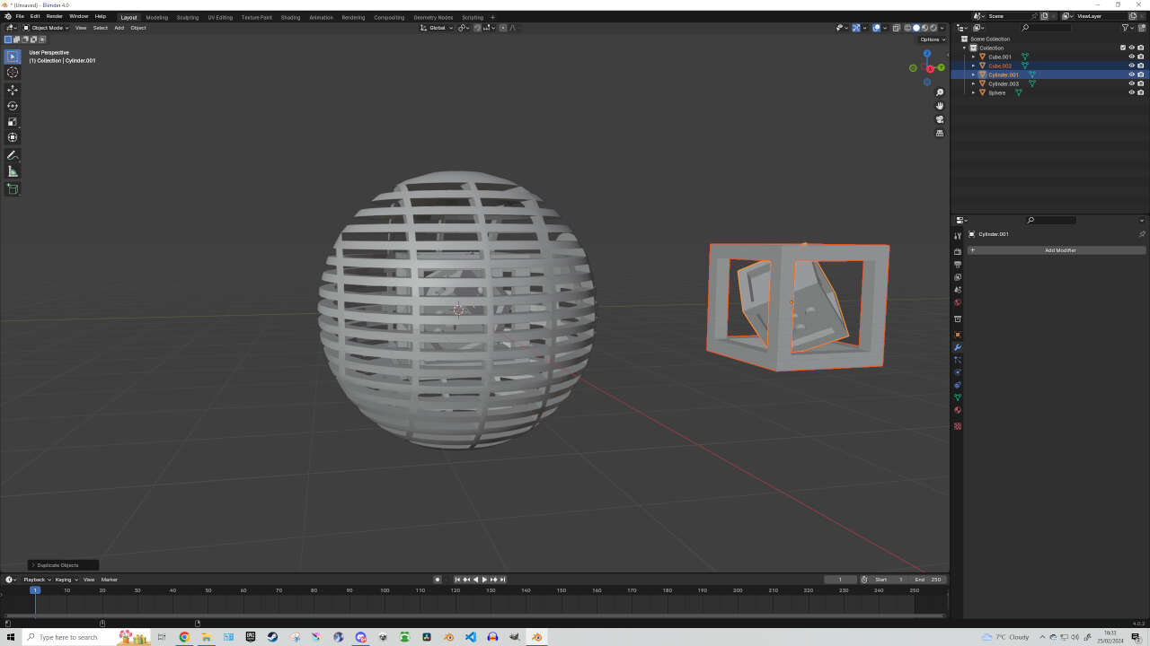
Add Spherical 3D Design: Using the method mentioned previously, select your Hollowed Cube and reset the Location (Select & Backspace the Transform metrics), then do the same for the die6. Now that they are both in the center, we need to create a spherical object that will house the other two designs we made. Feel free to duplicate your Cube designs and move them off to the side, as we can print these on their own too!

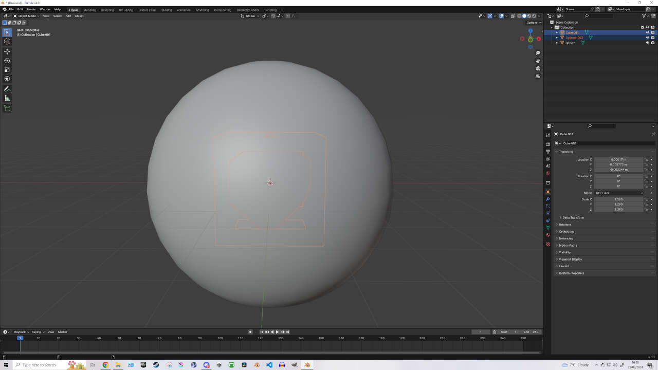
Making the outer shell: Right-Click the workspace -> Add -> Mesh -> UV Sphere
S (Scale) your sphere to be big enough to envelope the cube designs, then hit Enter. Then Right-Click the UV Sphere and click on ‘Shade Auto Smooth’ to give the sphere a smooth design.
Now Add -> Mesh -> Cube. With the new Cube selected hit S (scale), X (X-axis), drag the mouse until the cube stretches outside of the Sphere on either side, then hit Enter to set the scale. This time with the stretched out Cube selected hit S (scale), Z (Z-axis), drag the mouse until the cube flattens enough to look like a board or plank of wood, then hit Enter to set the scale. (We will name this object ‘Plank’ for tutorial purposes).
With the Plank object selected, go to the Modifiers tab and hit ‘Add Modifier’. In the search bar type ‘Array’ and click on the Array modifier. The Array modifier will allow us to create and manipulate the object easily. In the Array modifier change the ‘Count’ to 6, then just below for ‘Relative Offset’ set Factor X to 0, Factor Y to 1.200 and Factor Z to 0. This should give us 6 planks across the Y axis that are distanced appropriately. Editor's Note: You may need to adjust the position of your Array’d object. You can do this by pressing G (Grab), Y (Y-axis) on the object to move all 6 planks on the Y Axis. Scale appropriately so that each plank is sticking out of the front and back of the sphere, then Enter to set the scale.
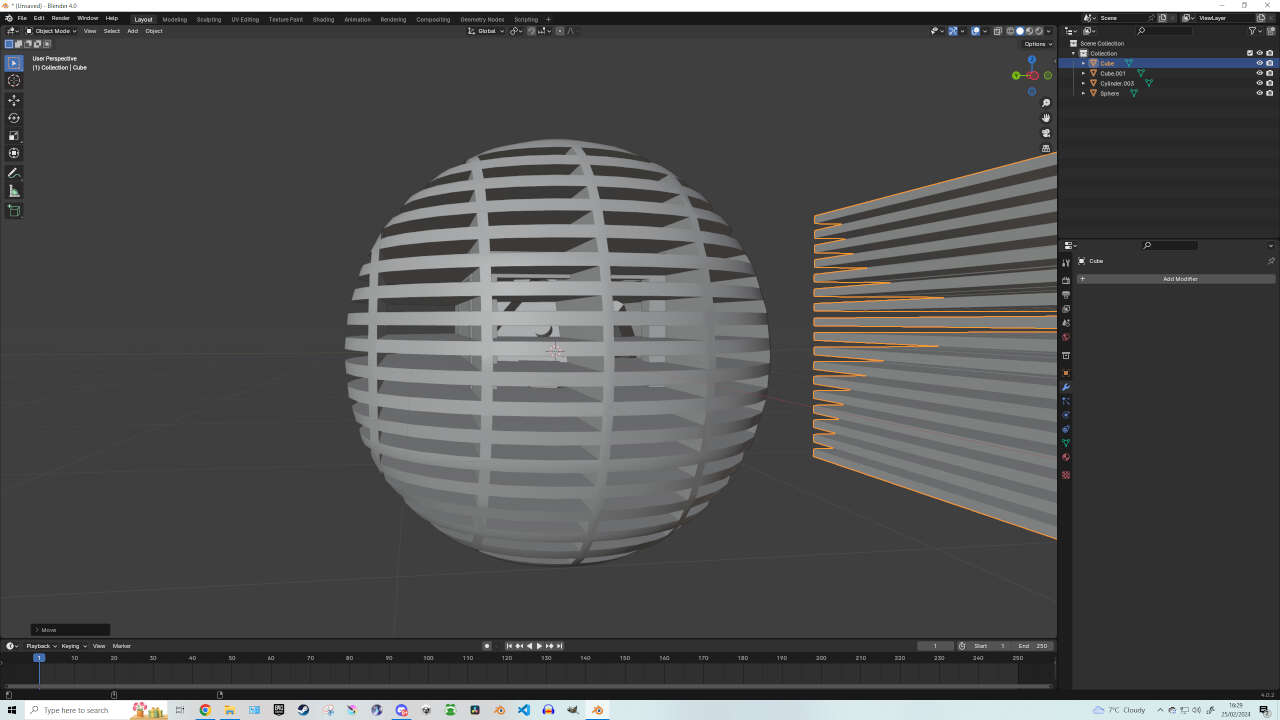
With the Planks object selected, create another Array modifier by going to the Modifiers tab and hitting ‘Add Modifier’ again. In the search bar type ‘Array’ and click on the Array modifier. In the new Array modifier change the ‘Count’ to 16, then just below for ‘Relative Offset’ set Factor X to 0, Factor Y to 0 and Factor Z to -2.500. This should give us a total of 96 planks across the Y & Z axis that are distanced appropriately. Editor's Note: You may need to adjust the position of your Array’d object. You can do this by pressing G (Grab), Z (Z-axis) on the object to move all 6 planks on the Y Axis. Scale appropriately so that each plank is sticking out of the front and back of the sphere, with the top and bottom of the sphere still visible.

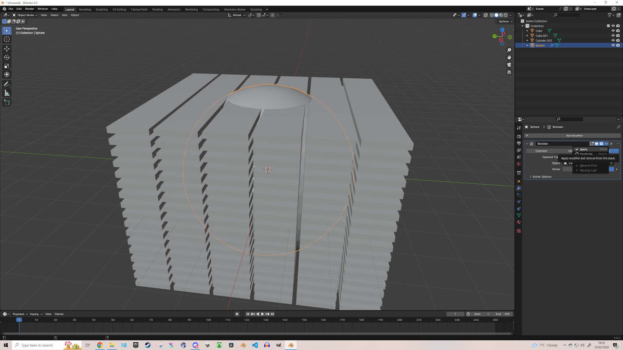
Now hit ‘Apply’ on BOTH Array modifiers. With that done, select your Sphere object and Add Modifier -> Boolean. Now select the Colour Picker icon and click on the Planks object. Now hit ‘Apply’ in the Boolean modifier and move / delete your Planks object. Your Sphere should now have empty slots or ‘vents’ lining the inside of it.

This, of course, only shaped the vents. There’s still no space for our Cube objects to roll around inside once printed. So to empty that space in between the Sphere, we need to Add -> Mesh -> UV Sphere. Then with the UV Sphere selected press S (Scale) and drag your mouse enough so that your new sphere covers the inside of the outer sphere. Just don’t scale it to overlap the outer sphere. We want the outer sphere to act as a shell that houses out Cube designs. When appropriately scaled, select the outer sphere and navigate to the Boolean modifier. Use the Colour Picker to select the inner UV Sphere and hit ‘Apply’ in the Boolean Modifier. If done correctly, your Outer Sphere will look like a type of Shell.
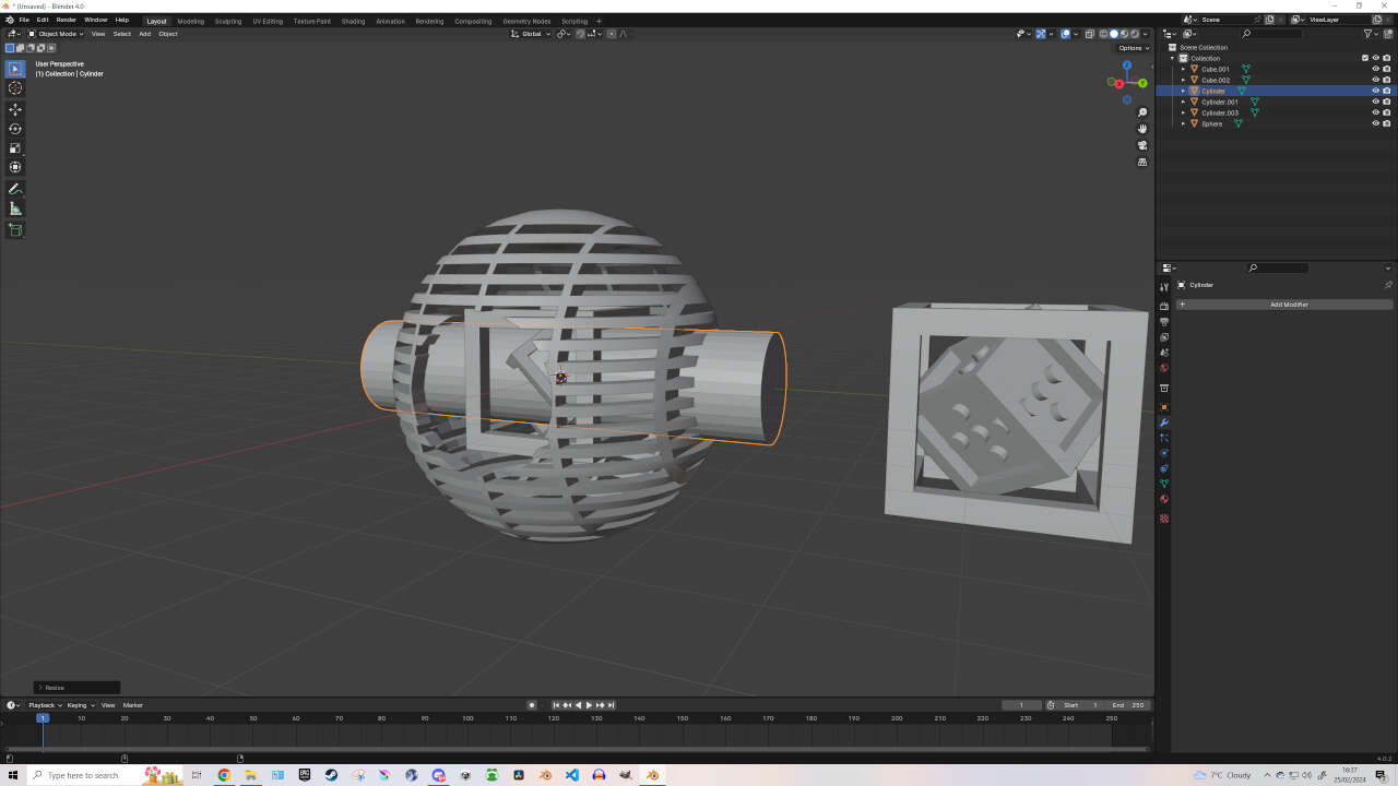
The assignment design is essentially done at this point but I am not satisfied because it is too hard to see the cube designs. But there’s an easy fix to this! Add -> Mesh -> Cylinder. Then with the cylinder selected -> R (Rotate) -> Y (Y-axis) -> 90 (90 degrees) -> Enter. Then press S (Scale) -> X (X-axis) -> drag until your Cylinder goes through the left and right side of the Sphere -> Enter.
Then with the Sphere selected, use the Colour Picker to select the Cylinder and hit “Apply” in the Boolean Modifier. This should have created a hole on either side to see through.
Editor's Note: Make sure your Cylinder isn’t bigger than your Cube objects or else they will fall out of the Sphere - defeating the purpose of the assignment.

Finally, with the cylinder selected -> R (Rotate) -> Z (Z-axis) -> 90 (90 degrees) -> Enter.
Then with the Sphere selected, use the Colour Picker to select the Cylinder and hit “Apply” in the Boolean Modifier. This should have created a hole on either side to see through. To finish off, we need to save this design by going to File -> Export -> STL -> then save at a desired location.
That’s the finished design! Congratulations! ^^
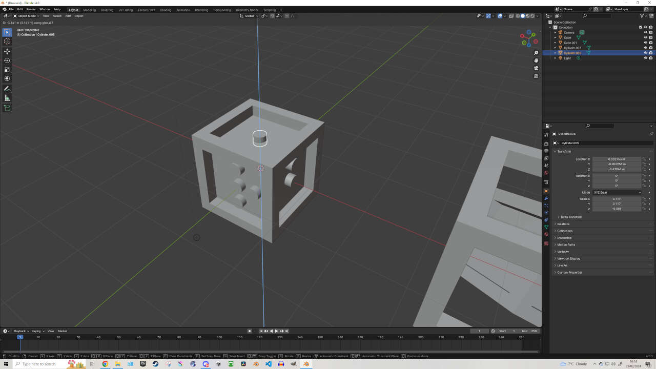
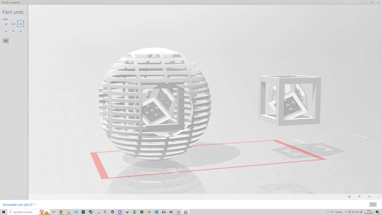
Editor's Note: If your design is like how mine currently is, that could cause complications during the slicing / printing process - such as having too many supports crawling around the inside, making their removal difficult and possibly damaging to your design. If you want to make the print go smoothly, I recommend orientating the designs (using Location, Rotate & Scale metrics) as shown below to reduce the heavy overload of support structures.


____________
Printing my 3D Design
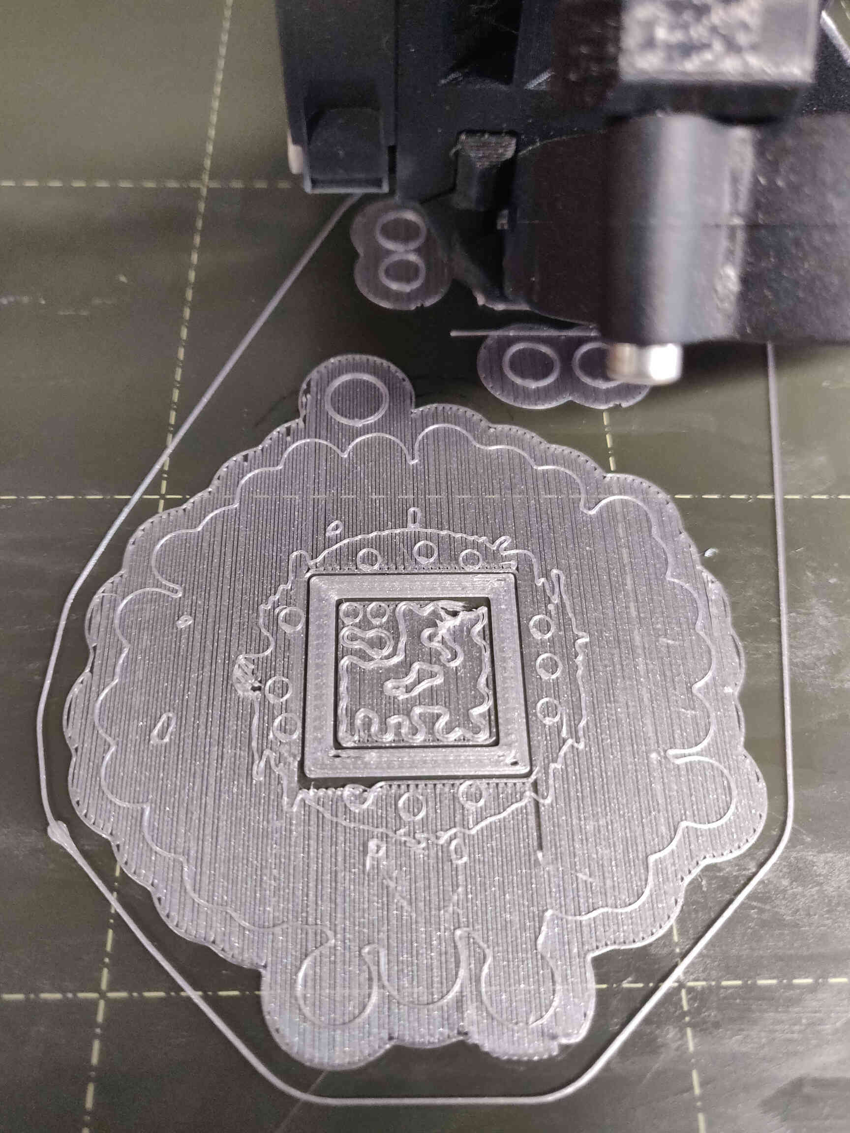
The 3D Printing process for this design is pretty straightforward. I chose to print the design using the Prusa i3 MK3S 3D Printer as it happens to be my favourite printer. Why? It’s super reliable and its slicer “PrusaSlicer” comes with a tool that will make your designs watertight - whereas Ultimaker’s ‘Cura’ slicer only has that option via paid addon. So let’s get to printing!

Open up PrusaSlicer, then drag and drop in your STL file. The tools tab on your left will have an option to Scale your designs to whatever size you want. First off, look at the top right corner and set the Print Settings to “0.20mm QUALITY” and Filament to ‘Generic PLA’. Also set up your Printer if need be.
After that, we need to go to the other ‘Print Settings’ tab on the top left corner of PrusaSlicer. On the left hand side, go to ‘Support material’. Now scroll down until you see in bold ‘Options for support material and raft’. Just below it where it says ‘Style’, change it from Grid to ‘Organic’. This will allow us to print with tree-like supports that will be useful in having supports weave through the designs rather than having the Grid supports encase our delicate design - potentially causing difficulty and damage during the removal process. Now return to the ‘Plater’ tab on the top left.
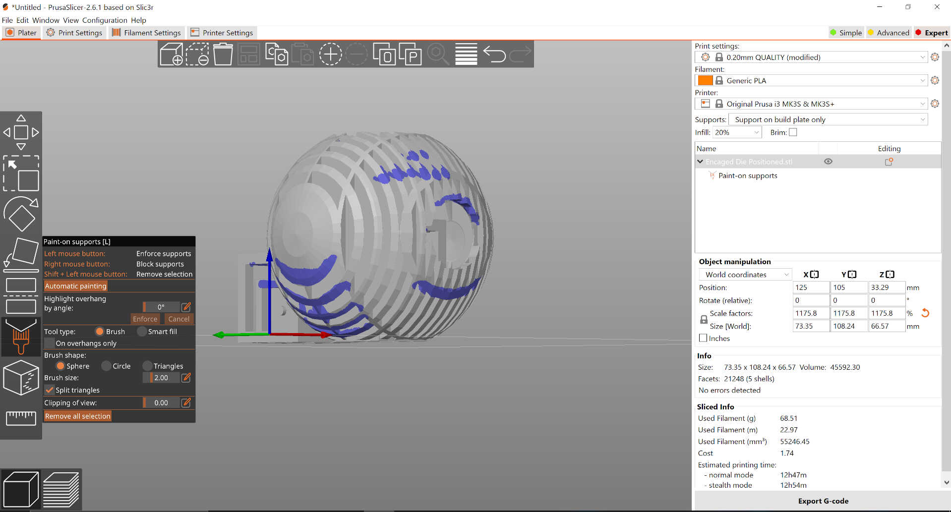

On the top right corner you should see a tab for ‘Simple’, ‘Advanced’ and ’Expert’. Click on ‘Expert’ to give us more options but mainly to allow us to use the ‘Paint On Supports’ tool.
On the left hand side below the Scale & Positioning tools, there will be a paintbrush-looking icon called ‘Paint On Supports’. With this tool, we can paint around the areas that we feel need the most support - without the slicer app getting ahead of itself by placing supports anywhere and everywhere. To use this tool, just draw on your design where the most important supports should go.
Once that’s finished, there’s one more thing you need to check. Next to the file name on the right hand side of PrusaSlicer, there might be a ‘danger’ or ‘warning’ icon next to your file name. If so, this means your design has some errors leading it to not be watertight - which could dramatically affect the print process. Double click on this icon and PrusaSlicer will automatically fix and design errors. Would recommend not over relying on this feature, but it’s definitely handy!
With your design repaired, next hit the button at the bottom left corner called ‘Slice’.
This will translate the 3D drawing into a language that makes a viable 3D Print.
Once complete, you should be able to see the supports encasing your design, as well as how much material will be used, how long to print, etc.
Finally, once you’re happy with the settings, go to the bottom right corner and hit ‘Export G-Code’.
Save this file on a MicroSD card, as that will be inserted into the Prusa. Once the file is exported, bring the MicroSD to the Prusa Printer and slot it into the left side of the console. Select the G-Code file you exported and hit ‘Print’. While the bed is warming, you can put on a small layer of glue - either Pritt Stick or the industry standard bed adhesive. This will help keep our design in place as a precaution, though not always necessary.
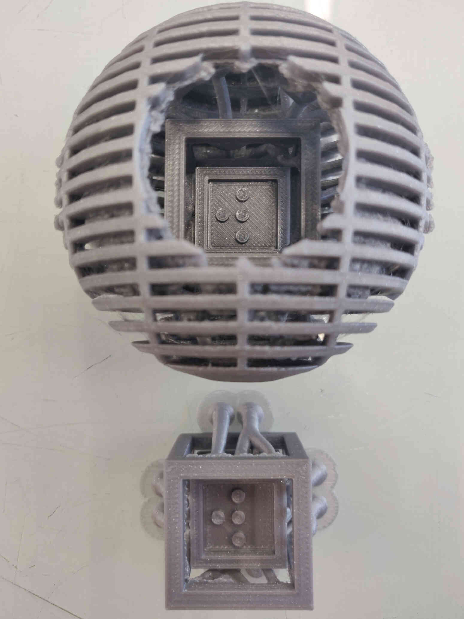
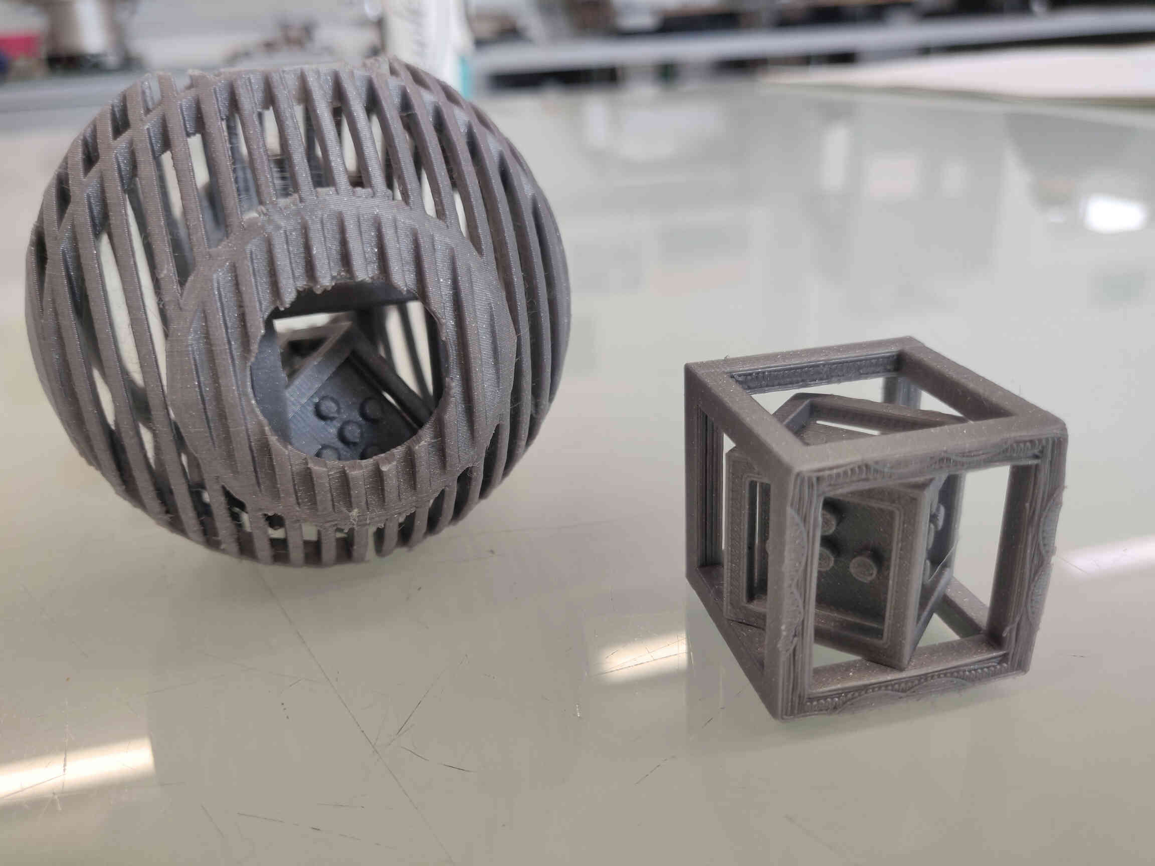
The Result
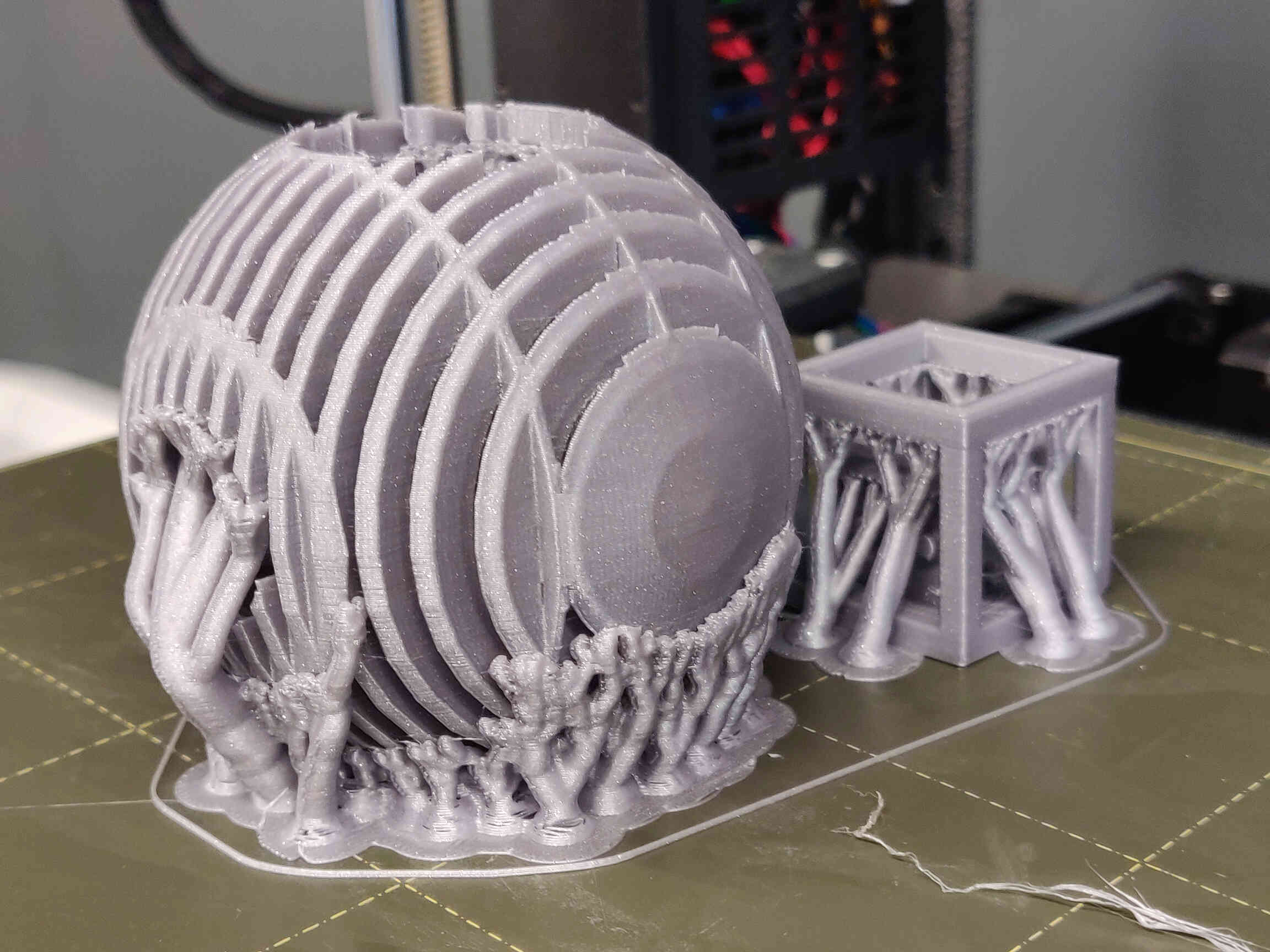
13-ish hours later, your design should be printed! Remove the supports using pliers and sand smooth out edges with soft sandpaper if you’re fancy. AND THAT’S IT! You now have a bona fide 6 sided die, within a hollowed out cube, within a death star! Feel free to shake it around, through it or stick it into an actual blender. The choice is yours! ^^
____________
Conclusion & Thoughts
3D Scanning and Printing was the subject I was looking forward to the most as it was one of the more expressive weeks so far, and a process that I am more so experienced with compared to most other subjects in Fab Academy. There were a ton of apps and tools that I wanted to test out and explore. Starting with 3D scanning tools like Scannerverse & PolyCAM, I got used to the availability of free 3D scanning tools found on my iPad and was impressed with the results after spending some time on it. Even without a LIDAR sensor, the detail picked up was incredible - though still lacking in many areas.
For 3D Printers, I was accustomed to using Prussa printers the most, so I wanted to test out Cura slicing and Ultimaker machines as they were the most prevalent machines in our fablab. In the end I can say without a doubt that I MUCH prefer the Prussa printers due to their reliability and ease of use when slicing g-codes. I unfortunately did not have enough time to test out the Artec Leo scanners - a lot of my time near the end was spent trying to fix a human scan I did for printing, which eventually came out very well. Hopefully I’ll get another chance soon enough.
Creating the Non-Subtractive Design in Blender was a satisfying process as I had free reign to create whatever I wanted - though I still stuck with something basic to avoid complications. The results of which were fairly on-point. Even got some gorgeous photos of the printing process. I’m definitely looking forward to the day I can own a Bamboo or Prussa machine in my own home.
____________