Electronics Disign.
I decided to design an electronic board that, in the future, will allow me to control a servo motor. I decided to reuse the XIAO 2040 microcontroller that we had used weeks earlier. Therefore, this board is inspired by QTorres. I also chose this approach because my knowledge of electronics is very basic, and I prefer to start with something simple. For the design, I used Fusion software. A video that I recommend for getting started with this software for circuit design is:
Board design on YouTube
But don't worry, before making this simple design, I had to learn several things that I will outline in the following steps.
While researching how to control servo motors, I found these two videos that I recommend for anyone who wants to get started with the topic.
Video 1 - How to assemble a servo motor control circuit. Video 2 - How to assemble a servo motor control circuit.Once I had a clear idea of the circuit components, I researched how to do it in Fusion. A resource that helped me get started with circuit design in Fusion is:
Video 2 - How to assemble a servo motor control circuit.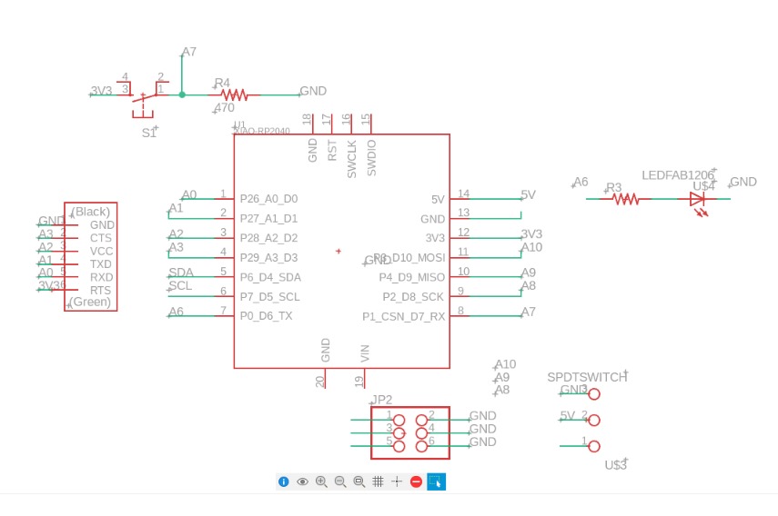
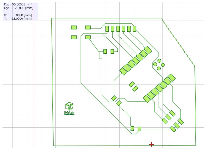
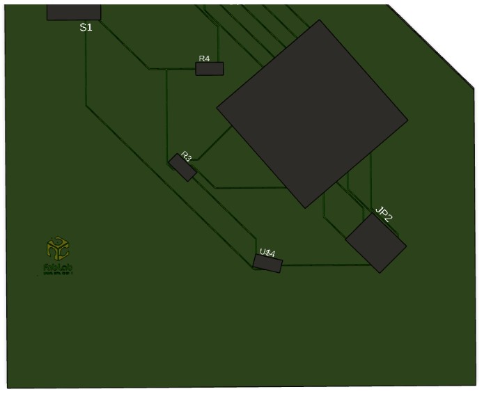
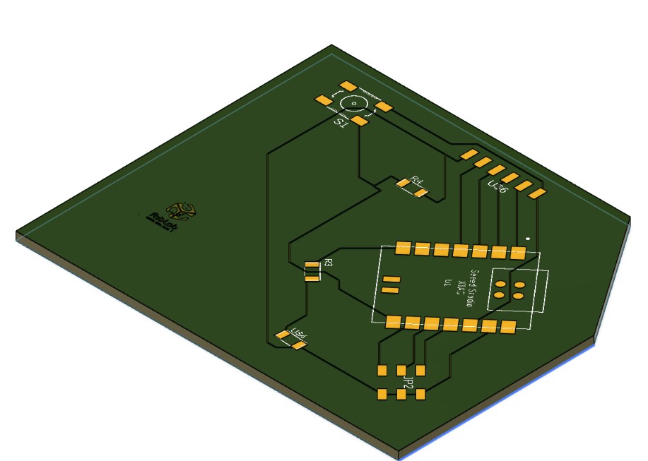
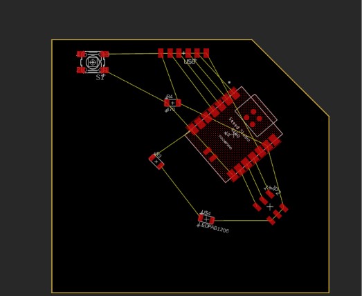
Figure 8.4 and 8.5 - 3D boad design
With the design completed, we can configure the geometry and prepare the files to make the board on the CNC router.
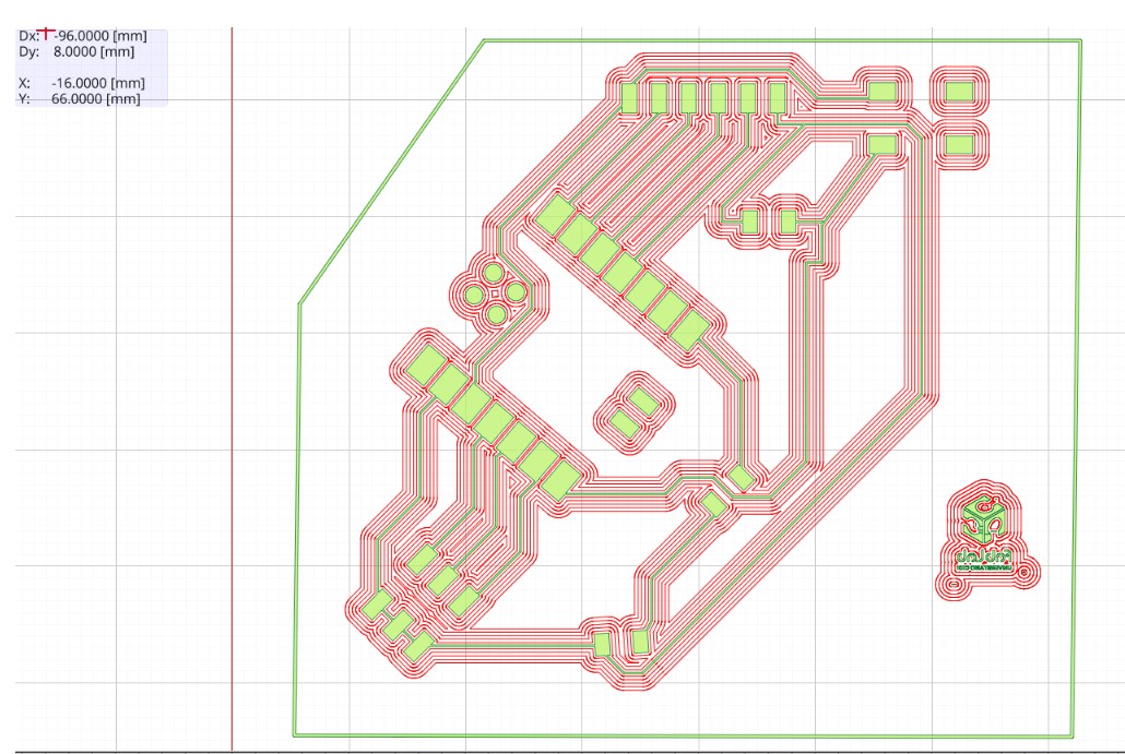
Afterward, we will save it in Gerber format.
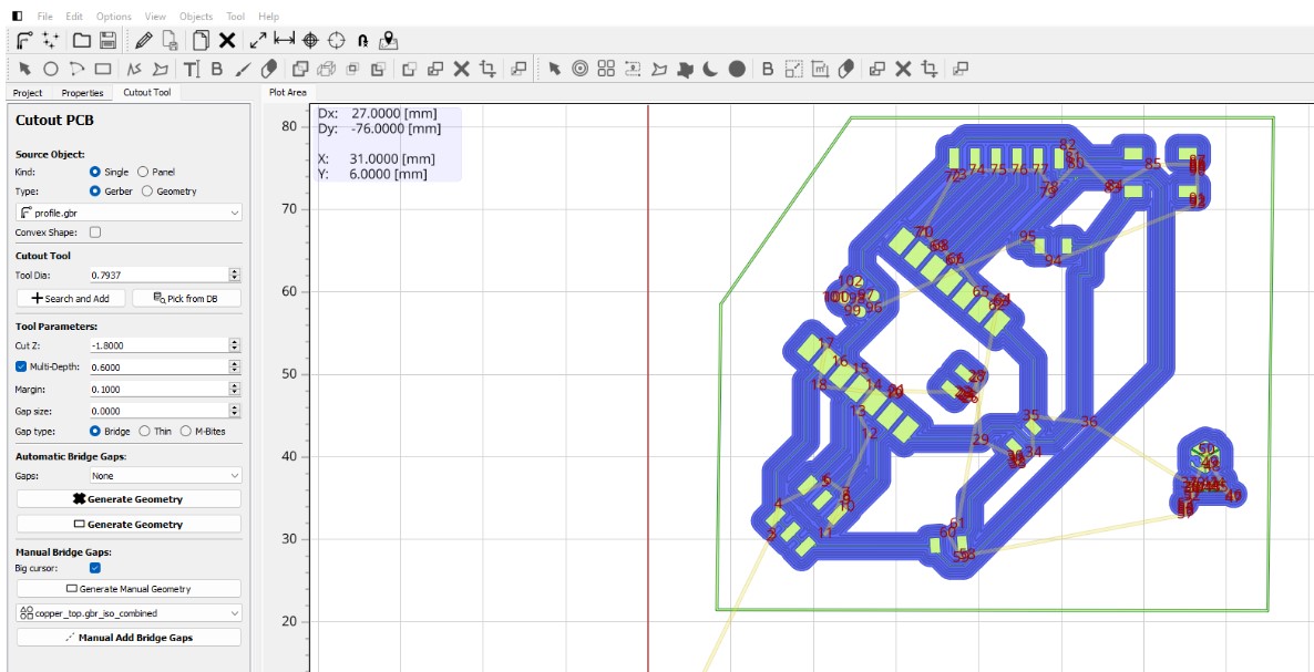
At this stage, we need to configure the parameters of the milling cutter that we will use to engrave the tracks and to make the cuts, as well as the depth and the number of passes, ensuring that they do not negatively affect the design.
We will create two files with different configurations. The first will be an isolation file that will mark the tracks, and we will save it as a Gerber file

Next, we will configure the cutting parameters of the electronic board
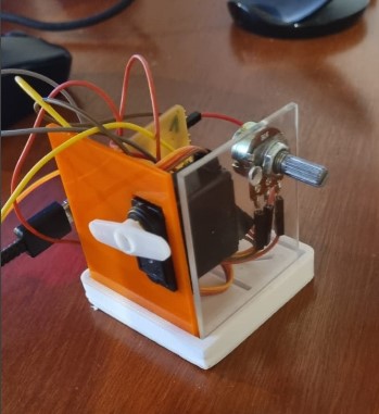
TIn order to protect the board and electronic components, and to be able to place the potentiometer and servo motor in the future, I decided to create a modular box.
The case consists of a base and a top lid with the same design made with 3D printing using ABS filament, and side walls made of acrylic 2mm thick cut with a laser.
The base will have slots to place the side walls and to hold the board upright, and the side walls will have holes to accommodate a potentiometer and the servo motor
For a couple of weeks, there were serious electrical problems on campus that particularly affected the FabLab, preventing us from using the CNC machine for a long time. As a result, the board could not be printed within the expected timeframe.