Multimeter
- What is a multimeter
- Which one do we have in the lab
- Using the tester to measure voltage
Oscilloscope
- What is an oscilloscope
- Which one do we have in the lab
- Using it to view signals
Multimeter
To start working with these types of tools we need to understand them better. I asked ChatGPT to tell me a bit about a Multimeter and here is what it said:
A multimeter is an electronic measuring instrument that combines several measurement functions in one unit. It is commonly used to measure voltage, current, and resistance. Here are the key features and functions of a typical multimeter:
Functions of a Multimeter
- Voltage Measurement (Voltmeter):
- Measures electrical potential difference between two points in a circuit.
- Can measure both AC (Alternating Current) and DC (Direct Current) voltages.
- Current Measurement (Ammeter):
- Measures the flow of electric current in a circuit.
- Can measure both AC and DC currents.
- Requires the multimeter to be connected in series with the circuit.
- Resistance Measurement (Ohmmeter):
- Measures the resistance within an electrical component or circuit.
- Useful for checking the continuity of wires and connections.
- Additional Functions (depending on the model):
- Continuity Test: Emits a sound if there is a low resistance path between the probes, indicating a continuous circuit.
- Capacitance Measurement: Measures the capacitance of capacitors.
- Frequency Measurement: Measures the frequency of an AC signal.
- Temperature Measurement: Some multimeters come with a thermocouple to measure temperature.
- Diode Test: Checks the forward voltage drop of diodes.
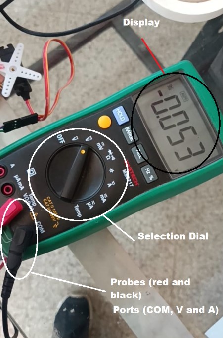
Parts of a Multimeter
- Display: Shows the measurement readings.
- Selection Dial: Allows you to choose the type of measurement and the range.
- Probes: Two wires with metal tips used to connect the multimeter to the circuit or component being measured.
- Red Probe: Typically connected to the positive terminal.
- Black Probe: Typically connected to the common (COM) terminal.
- Ports:
- COM (Common) Port: The black probe is always connected here.
- VΩmA Port: Used for measuring voltage, resistance, and small currents.
- 10A Port: Used for measuring high currents (up to 10A).
How to Use a Multimeter
- Measuring Voltage:
- Set the dial to the appropriate voltage setting (AC or DC).
- Connect the probes to the circuit across the component or section where you want to measure the voltage.
- Measuring Current:
- Set the dial to the appropriate current setting.
- Connect the multimeter in series with the circuit so the current flows through the multimeter.
- Measuring Resistance:
- Set the dial to the resistance (Ω) setting.
- Connect the probes across the component you want to measure.
- Continuity Test:
- Set the dial to the continuity test setting.
- Connect the probes across the path you want to test; if the path is continuous, the multimeter will emit a beep.
Safety Tips
- Always start with the highest range if you are unsure of the measurement range.
- Never touch the metal parts of the probes while measuring.
- Disconnect power to the circuit before measuring resistance.
- Ensure the multimeter is properly set up for the type of measurement you are performing to avoid damaging the device or the circuit.
Multimeters are versatile tools essential for anyone working with electronics, from hobbyists to professionals.
Multimeter from the Lab
According to this, we can start looking at the Multimeter we have in the lab and the parts it has:
Testing the multimeter
We used the Multimeter to test the voltage of one of our PCBs that has a LED. We turned it on and off with a little program and that is what we wanted to check how the voltage was behaving. Voltage_measure.mp4
In the video you can see that we used the probes to put the red one where the pin of the LED connection started and the black one in a GND position, so with this we can have the value of that whole section. The voltage varies a bit and is notorious that it doesn’t really reach the 3.3V that the XIAO supposedly has as an output.
After using the Multimeter, we went ahead and started to use the Oscilloscope. Again, a brief explanation thanks to ChatGPT to understand the tool better first:
Oscilloscope
An oscilloscope is a specialized electronic test instrument that allows you to observe the changing signal voltages, usually as a two-dimensional plot of one or more signals as a function of time. Here's a detailed explanation:
Functions of an Oscilloscope
- Voltage Measurement:
- Displays voltage changes over time.
- Allows you to see the waveform of the signal.
- Frequency and Period Measurement:
- Measures the frequency of a periodic signal.
- Displays the period of the waveform, which is the reciprocal of the frequency.
- Amplitude Measurement:
- Measures the peak-to-peak voltage, which is the difference between the maximum and minimum values of the signal.
- Phase Measurement:
- Compares the phase difference between two waveforms.
- Useful for analyzing signal timing and synchronization.
- Waveform Analysis:
- Allows you to analyze the shape of the waveform, such as sine waves, square waves, and complex signals.
- Useful for diagnosing and troubleshooting electronic circuits.
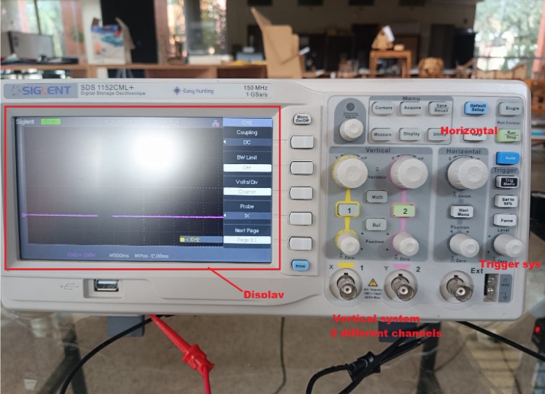
Parts of an Oscilloscope
- Display:
- Typically a screen (LCD or CRT) that shows the waveform.
- Displays the X-axis (time) and Y-axis (voltage).
- Vertical System:
- Controls the vertical scale (volts per division).
- Includes input channels for connecting probes.
- Horizontal System:
- Controls the horizontal scale (time per division).
- Adjusts the time base of the signal display.
- Trigger System:
- Controls the starting point of the waveform display.
- Allows you to stabilize a repeating signal by setting a trigger level and slope.
- Probes:
- Connect the oscilloscope to the circuit under test.
- Typically come with a ground clip and a probe tip.
- Probes may have a 1x or 10x attenuation setting.
How to Use an Oscilloscope
- Connect the Probes:
- Attach the probe's ground clip to a ground point in your circuit.
- Connect the probe tip to the point where you want to measure the signal.
- Set the Vertical Scale:
- Adjust the volts per division setting to fit the amplitude of your signal on the screen.
- Set the Horizontal Scale:
- Adjust the time per division setting to display one or more cycles of your signal.
- Adjust the Trigger:
- Set the trigger level to stabilize the waveform display.
- Choose the appropriate trigger mode (e.g., edge, pulse, video) based on your signal.
- Analyze the Waveform:
- Observe the waveform shape, amplitude, frequency, and any anomalies.
- Use measurement tools provided by the oscilloscope (cursors, automatic measurements) to quantify signal parameters.
Types of Oscilloscopes
- Analog Oscilloscopes:
- Use a cathode-ray tube (CRT) to display waveforms.
- Real-time display but limited in memory and advanced features.
- Digital Storage Oscilloscopes (DSOs):
- Use digital memory to capture and store waveforms.
- Offer advanced features like waveform storage, complex triggering, and digital signal processing.
- Mixed Signal Oscilloscopes (MSOs):
- Combine analog and digital channels.
- Allow simultaneous analysis of analog waveforms and digital signals (logic analysis).
Safety Tips
- Always use appropriate probes rated for the voltage and frequency of the signal.
- Ensure proper grounding to avoid electrical shocks and signal noise.
- Be cautious when measuring high voltages or working with live circuits.
Oscilloscopes are essential tools for diagnosing, troubleshooting, and analyzing electronic circuits, making them invaluable for engineers, technicians, and hobbyists alike.
Oscilloscope from the Lab
And again, let’s take a little look at the one we have in the lab with its parts:
Testing the oscilloscope
To test the Oscilloscope, we wanted to compare the values we got in the multimeter and see if we got something similar or not. We knew that the voltage was a DC voltage, and that it had a variation of pulses of 1s each, so basically for 2 seconds it was high, and 2 seconds it was low. Here the video: Oscilloscope_test.mp4
As you can see, we used the 500m/s division in the horizontal, and the 1V in the Vertical channel 2. In the Oscilloscope, the voltage was actually 3.3V, which was different from the multimeter, which leads us to believe that probably when it is an output like this one, the oscilloscope is better to have more precise readings.
Here you have the program we used: blink_groupal.py
