-
- Overview
- Laser Cutting--Parametric Construction Kit
- Laser Cutting--Chinese Lantern
- The idea of Chinese Lantern
- Create an sketch of the "Chinese Lantern"
- Solid Model Testing
- Decoration and Rendering
- Exporting SVG Files and Cutting Production
- Setup my laser cutting machine
- OK!It's time to cutting it!
- Get the Demo of Cutting result
- The final step!Assemble it!
- Vinyl Cutting--My FAB Sticker
- Team assignment
- Assignment files
week03-Computer-controlled cutting
Week 3 - Overview
In week 3, I learned about various methods of Computer-controlled cutting, techniques, and computer-aided design.
I also focused on learning how to use vinyl cutters and laser cutters.
I am very interested in the various materials that can be used for cutting,
as this will facilitate my exploration and application of more materials in future product design.
Starting this week, we need to complete two projects: a team assignment and an individual assignment.
characterize your lasercutter's focus, power, speed, rate, kerf, joint clearance and types
Link to our group page:
Week3 Group Assignmentcut something on the vinylcutter design, lasercut, and document a parametric construction kit,
accounting for the lasercutter kerf,which can be assembled in multiple ways,and for extra credit include elements that aren't flat
Reference Links
Week3 Computer-controlled Guide for my Fab Academy Journey.Version control & GitLab.
Laser Cutting--Parametric Construction Kit
1.Preparation Work
Software Introduction
I used Shapr3D to design the parametric construction kit.
Shapr3D is a software that allows users to create 3D models and animations using a drag-and-drop interface.
It is available for Windows, Mac, and Linux operating systems.
I downloaded the software from the iTunes store and installed it on my iPad.
It very easy to use and has a lot of features, including a 3D model editor, a path editor, and a rendering engine.
I just use my apple pencil to draw the designs and export them as DXF files.

Here is the link to the software's Introduction page: Shapr3D Introduction
Machine Introduction
I used a DAZUYUEMING CMA1610 Laser Cutting Machine in Chaihuo nodeto cut the parametric construction kit.
Here is the link to the machine's manual: DAZUYUEMING CMA1610 Laser Cutting Machine Manual

2.Manufacturing Process
Design
I will use a 3mm thick wooden board to complete this parametric construction kit.
My idea is to minimize the waste of wood while allowing for a variety of assembly tests.
This presents certain challenges in both design and machining,
but I am eager to try it.😂
OK, let's see the design's process:
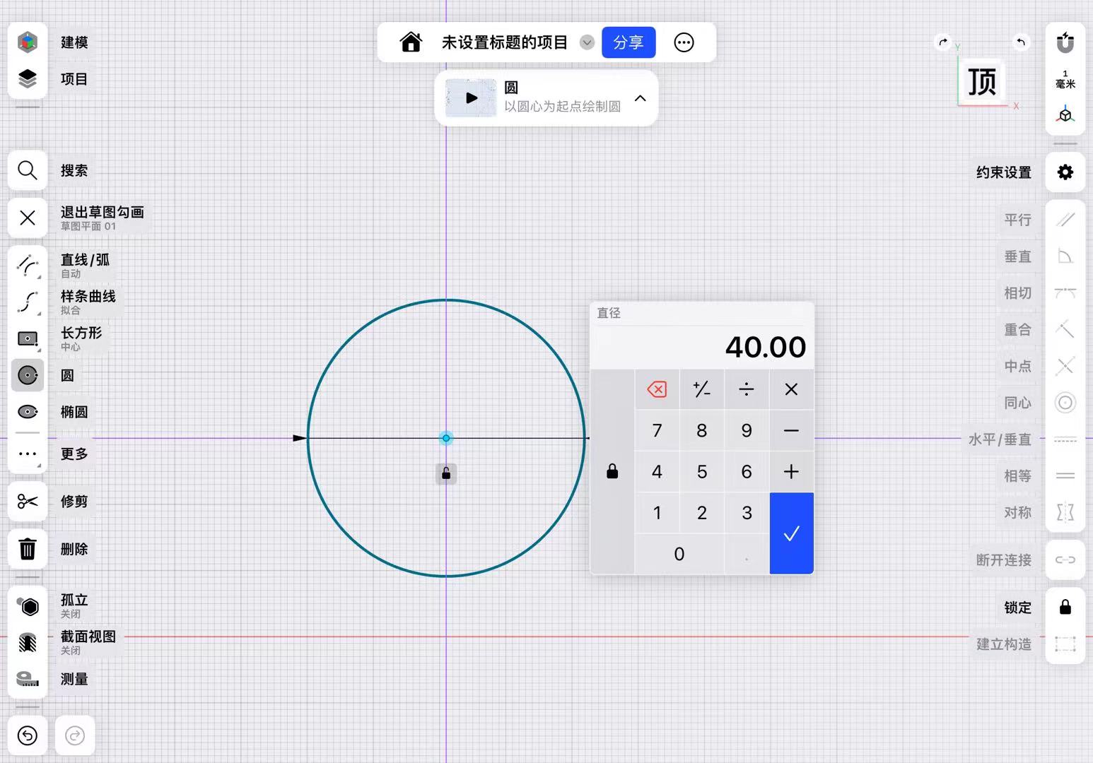
1. Draw a circle on the sketch and set the diameter parameter to 40mm.
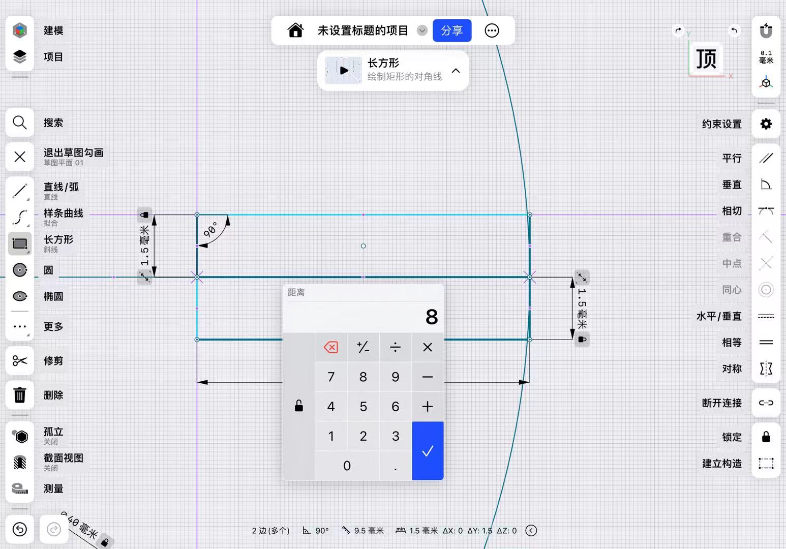
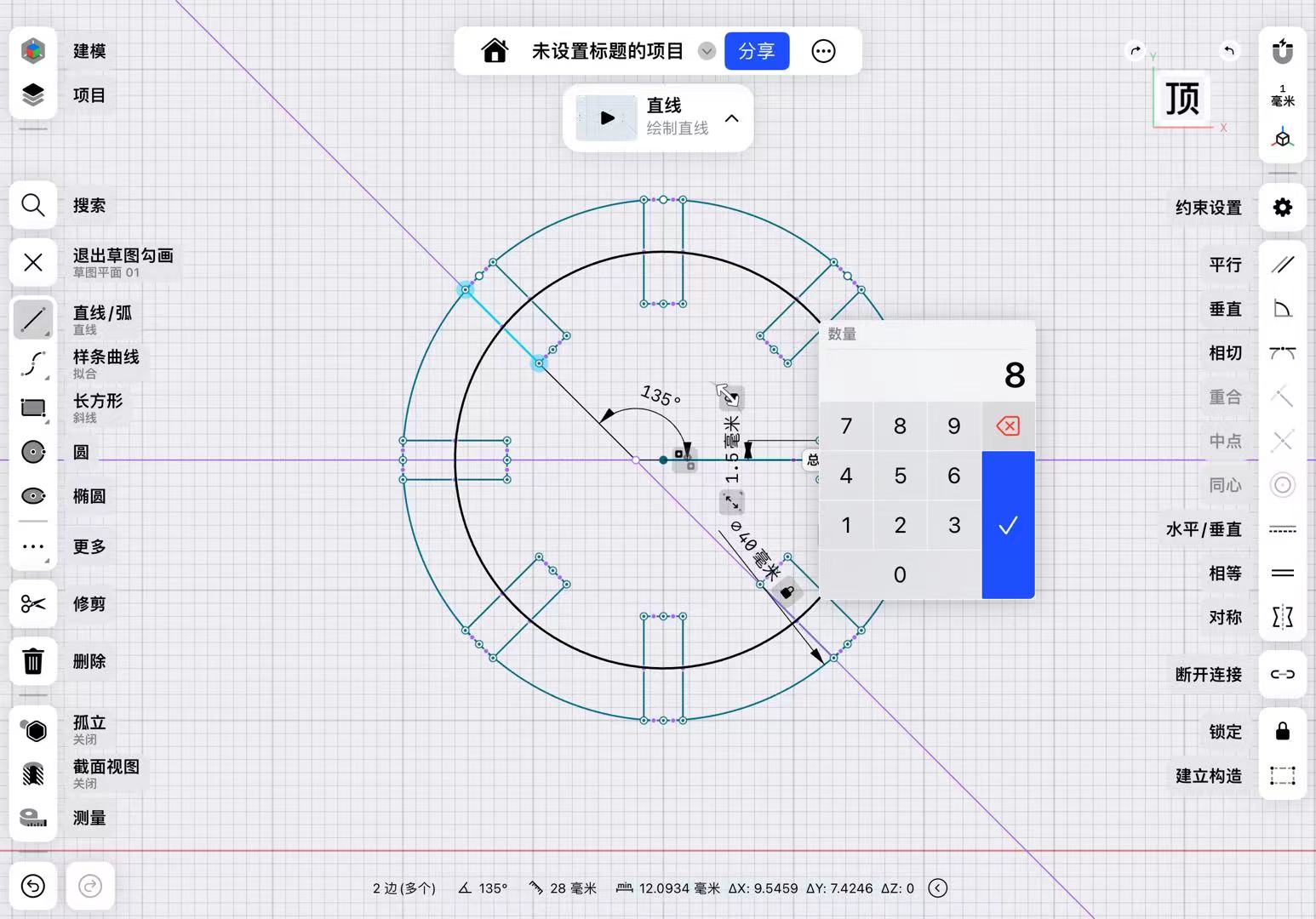
2. Draw a reference line that intersects with the circle at one endpoint, and draw a rectangle with dimensions set to 8mm in length and 3mm in width.
3. Use the circular pattern command, select the origin of the array, and set the array parameters to 8 items.
4. Adjust the longest edge of one of the rectangles to 12mm.
5. Use the extrude command, set the extrusion height to 3mm, to achieve my parametric design.
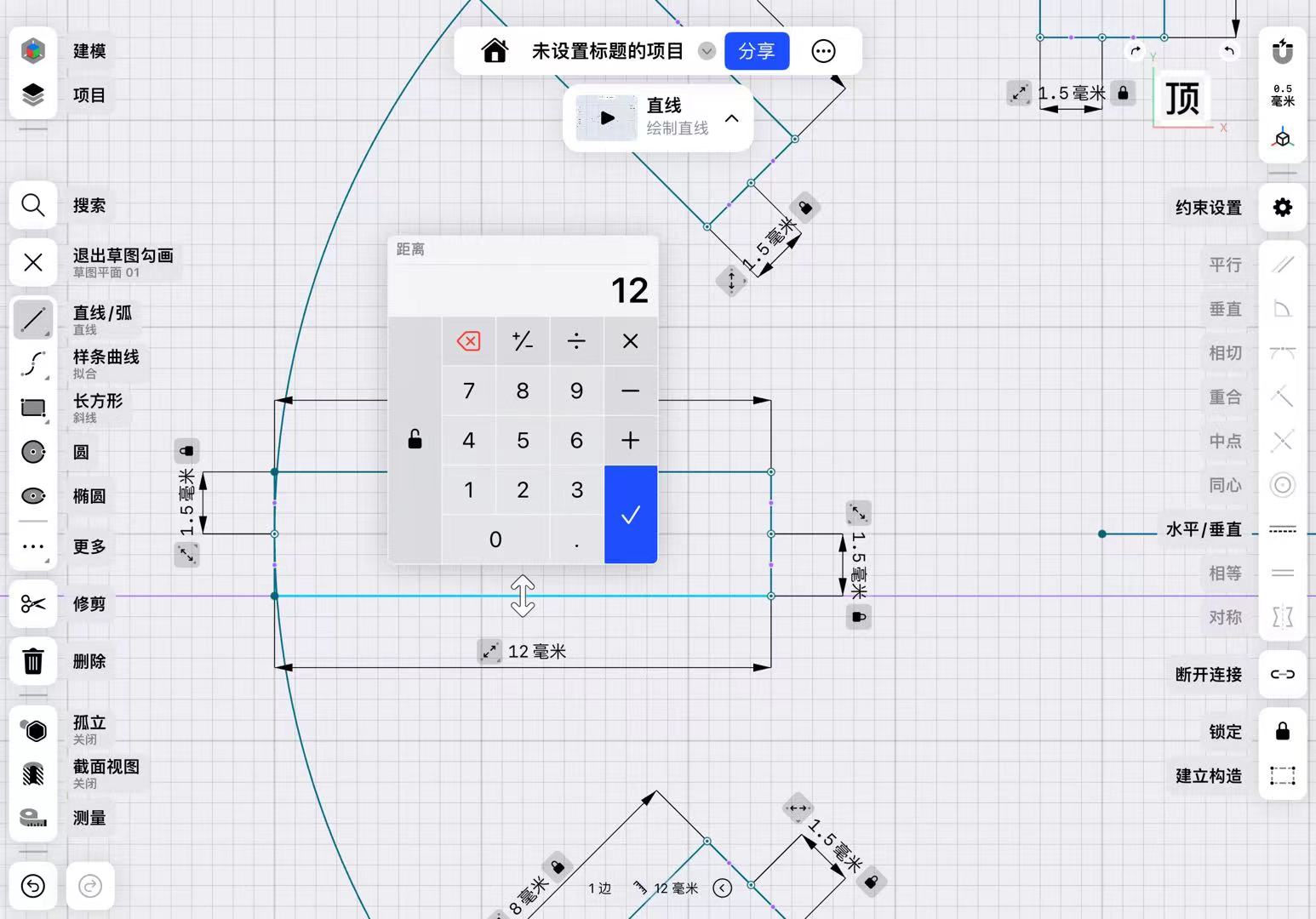

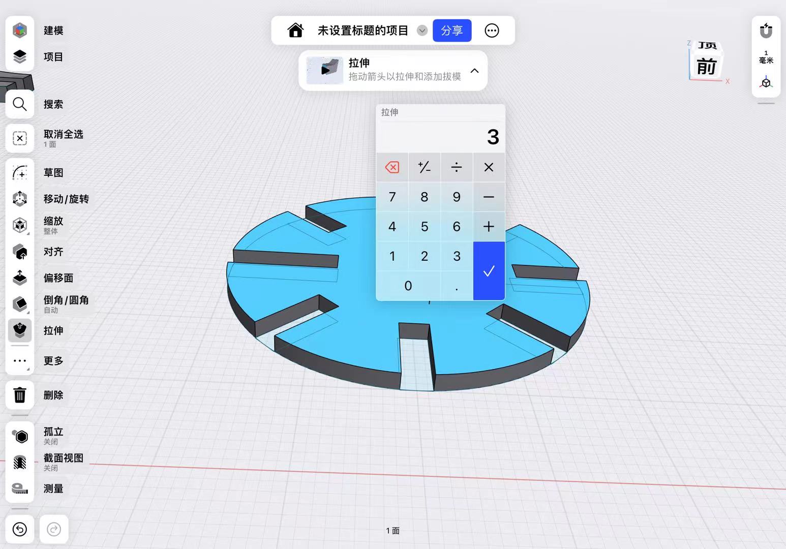
Using parametric modeling, I can obtain new parts by selecting the positions to be modified and changing the corresponding parameters.
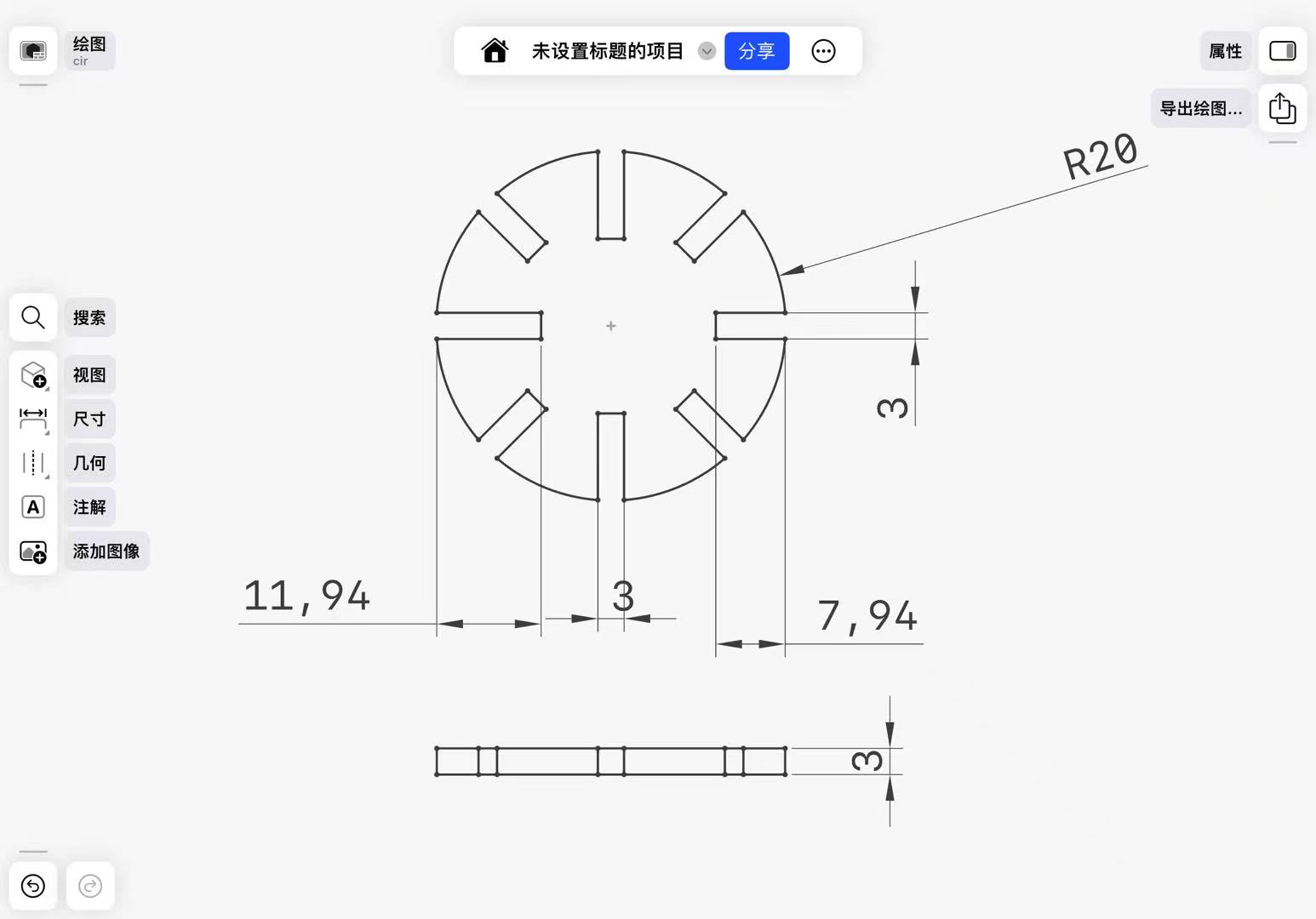
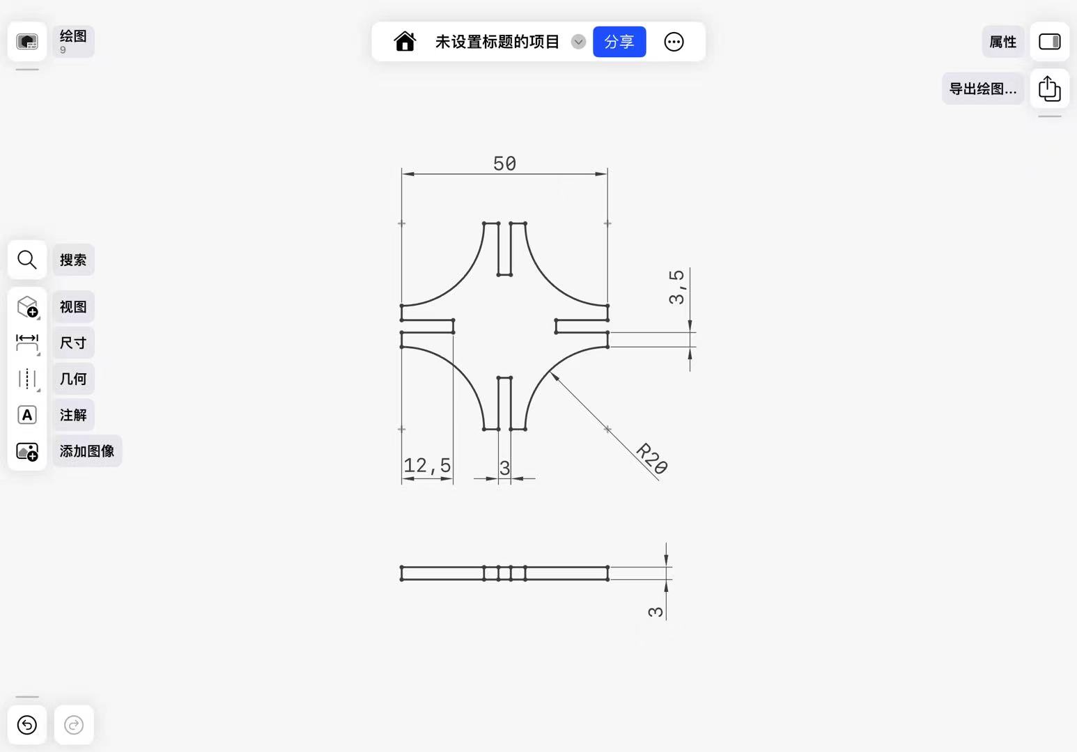
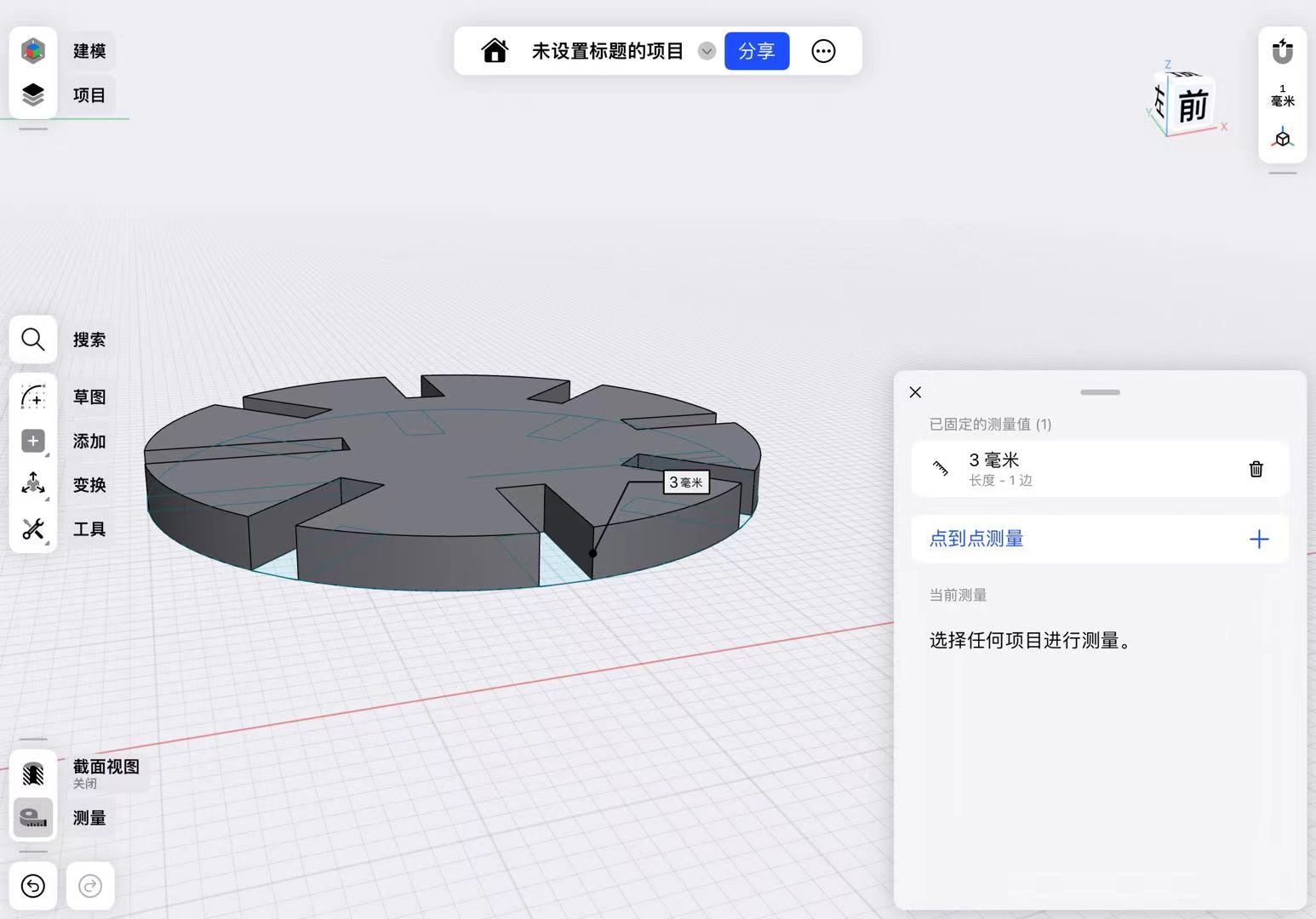
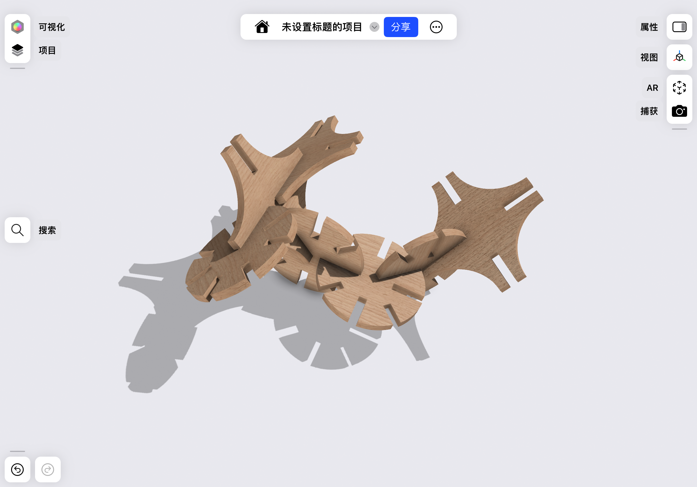
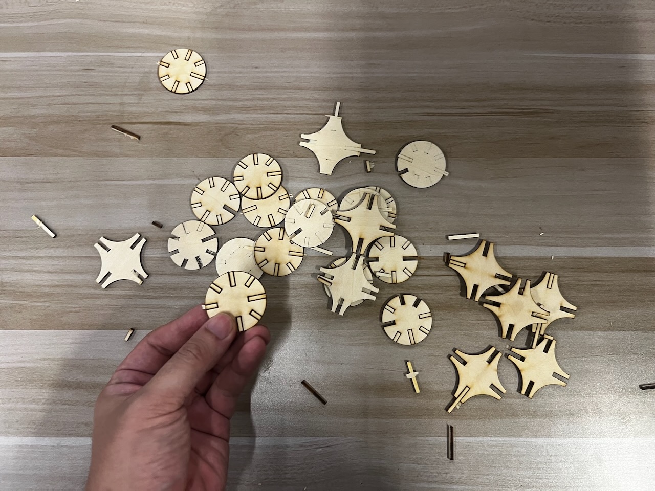
In the design, I was very pleased to find that both the circular shapes and the nearly rhombus-shaped small parts with central voids could be effective.
Thus, I completed the expected form through modeling and simple rendering in Shapr3D.
Later, I measured the thinkness of the board I am going to use, and it is about 3mm.
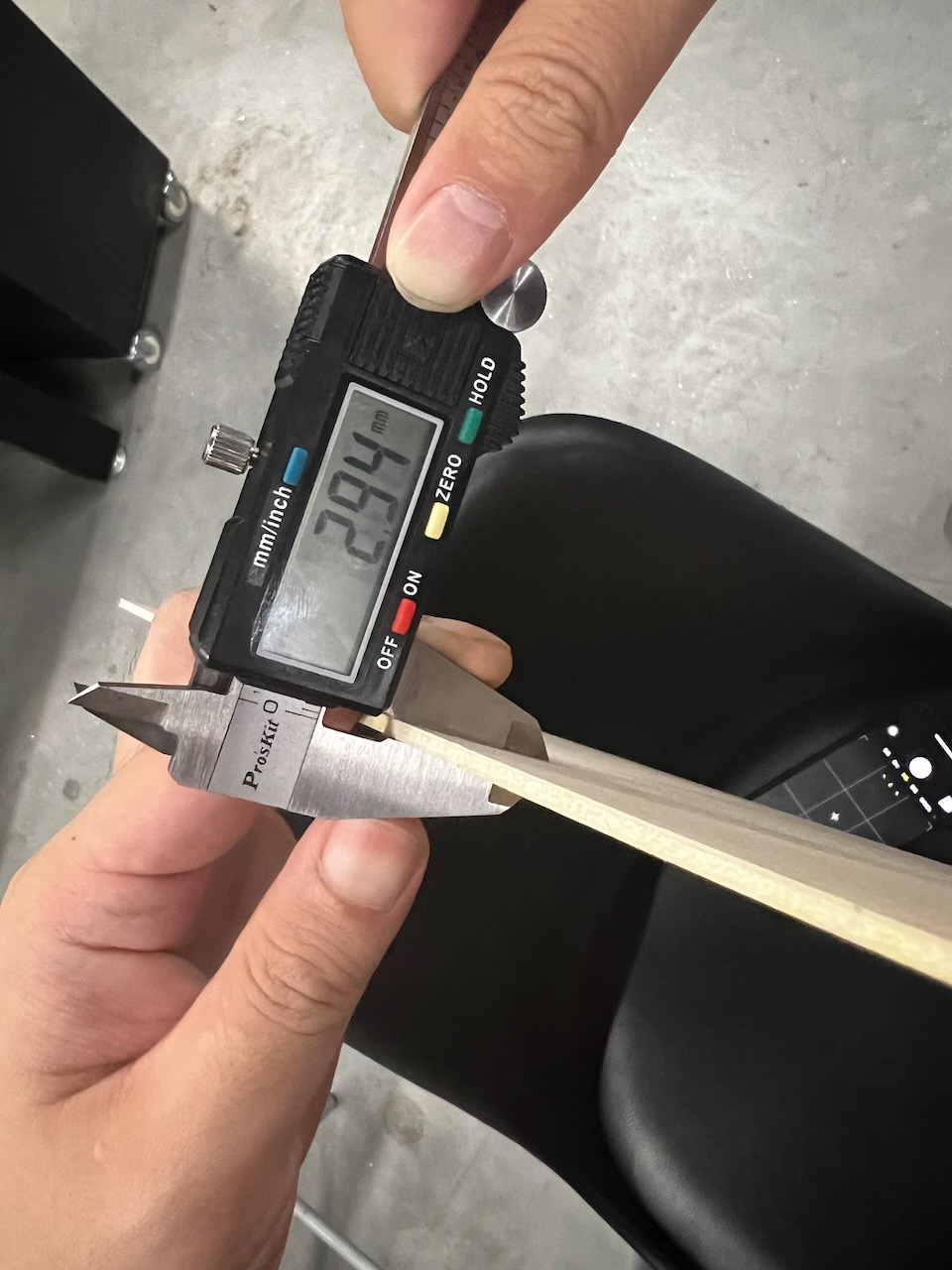
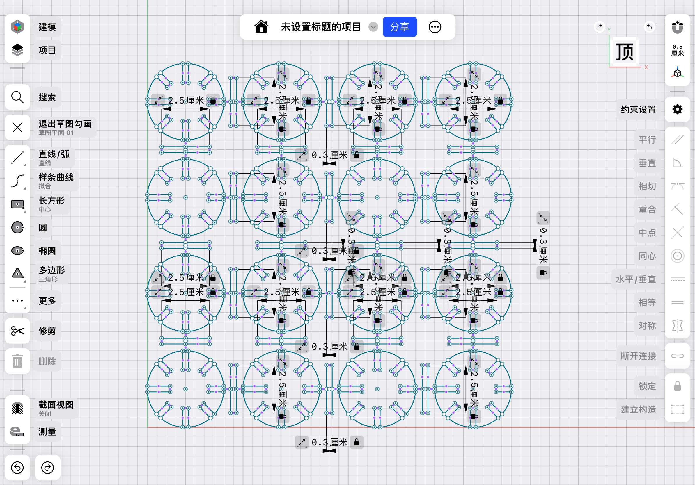
Then,based on the kerf tool made by my teammate Katherine, to make a construction kit to join tightly, I should set my parameter related to joint part to be 2.6mm.

So I changed the parameter in my construction kit to be 2.6mm.

Machining
First, our teammates tested the proper focus postion by using laser spot shooting on a paper, the smallest spot will be the best laser focus setting:

This DMA1610 machine uses a processing setup software called SmartCurve.
Secondly, I exported the file in DXF format, then transferred it to the control computer of the laser cutter.
This DMA1610 machine uses a processing setup software called SmartCurve.
I continued to use the 3mm thinkness board to cut.

After importing the file, I needed to set the cutting power and speed.
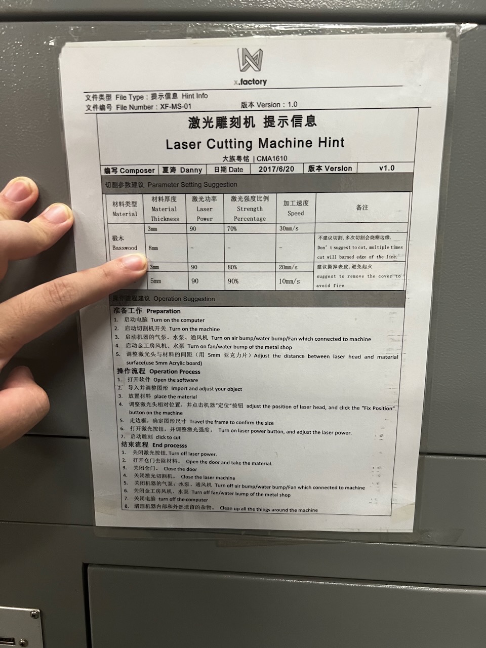
Based on the power and speed instruction sheet on the machine,the proper cutting speed for 3mm thickness of wood is 70% and the speed is 30mm/s
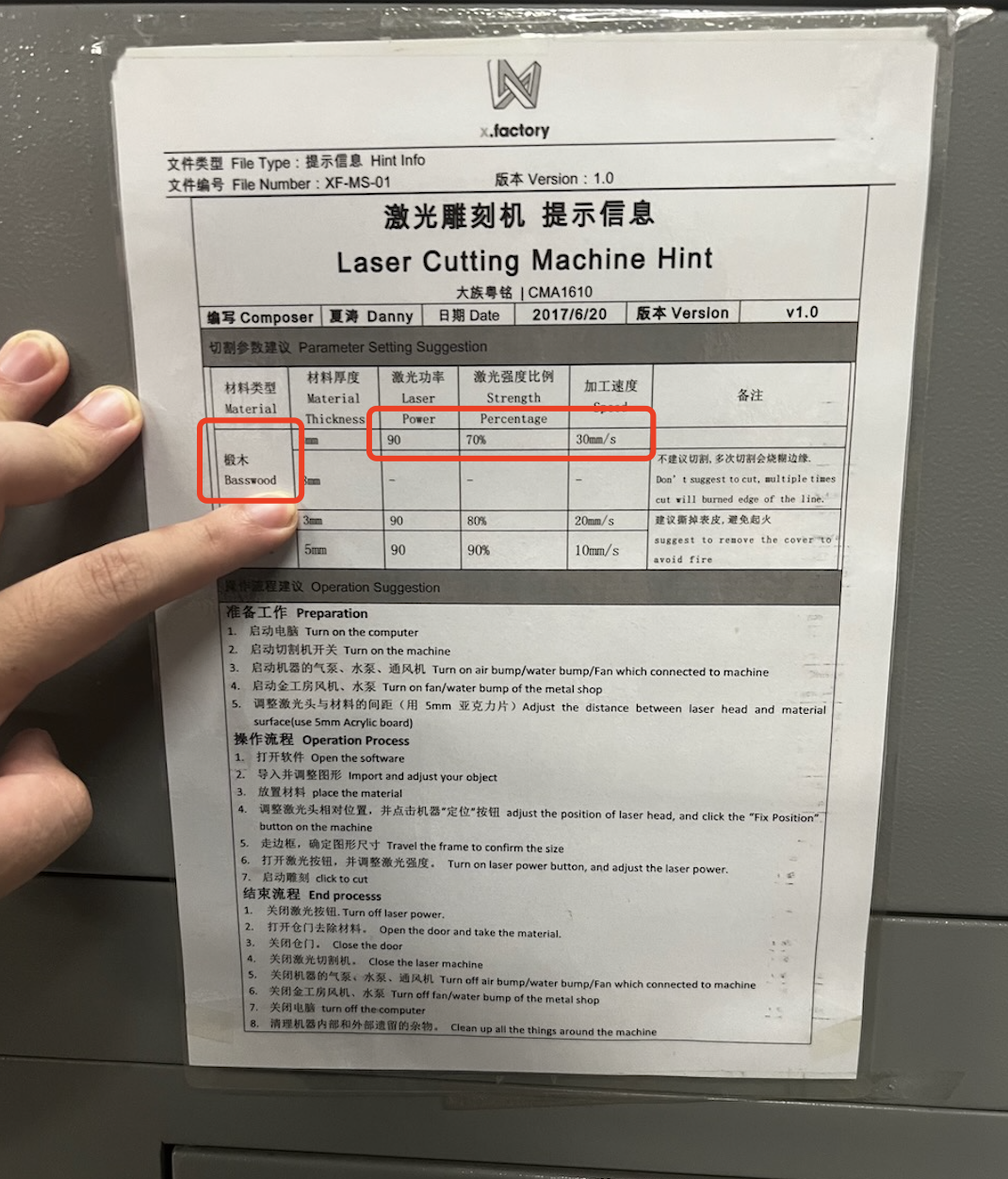
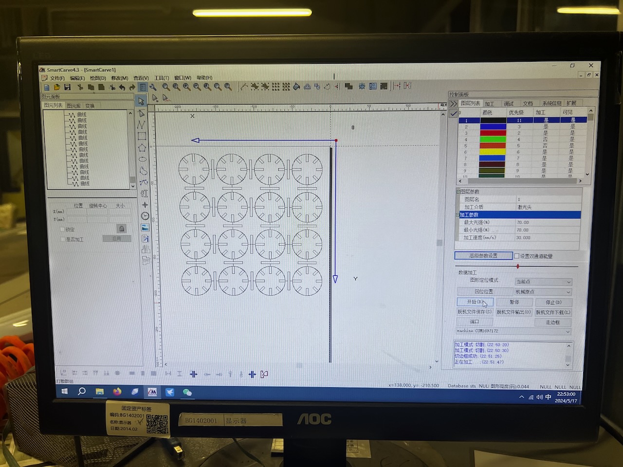
So firstly, I set the spped and power based on the sheet. The following image shows the parameters I finally set.

But later, based on the test result of our teammate Katherine's test about different power and speed for cutting through the wood, the power doesn't need to be set as 70%, actually 30% is enough. So I changed my setting of power to be 30%.
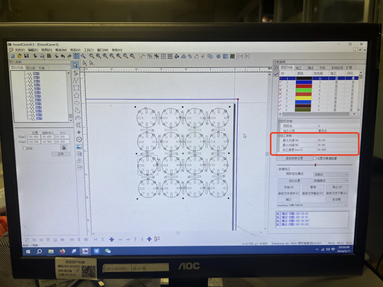
After setting the machining parameters, I connected to the laser cutter through the software, made initial settings, transferred the machining file, and prepared for cutting.

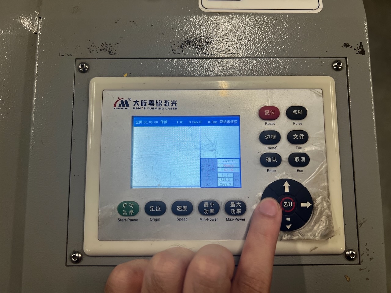
I have also performed a frame walking to trace the border of the design to ensure the cut lines are positioned correctly.

Next, we start cutting!

Note: Be sure to turn on the exhaust fan, as the wood we are machining is cut by laser sintering, which produces a large amount of harmful gases, so it is essential to use an exhaust fan!
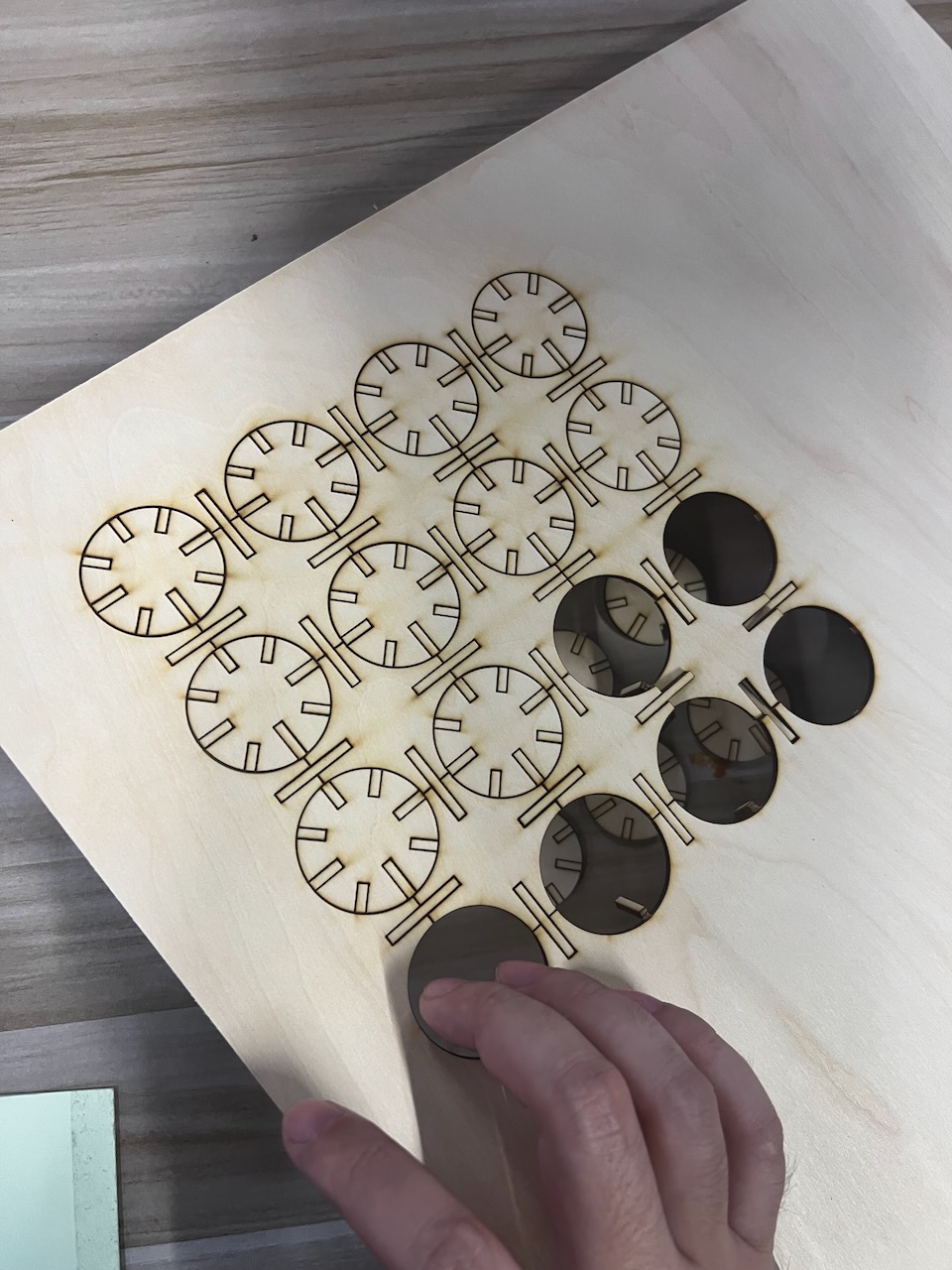
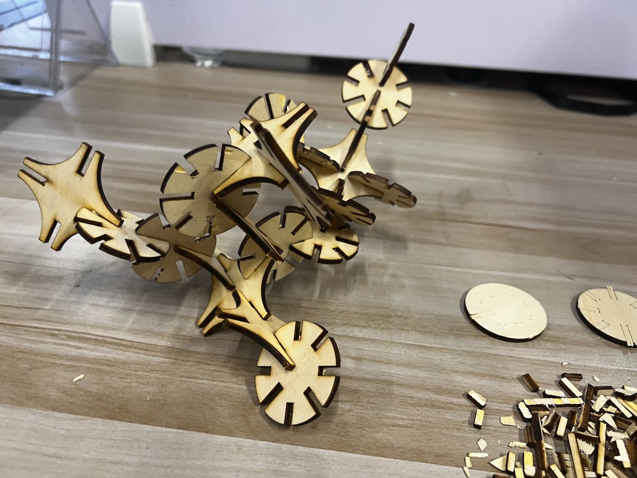
After the cutting is complete, I carefully remove the board from the machine and place it on a flat surface.
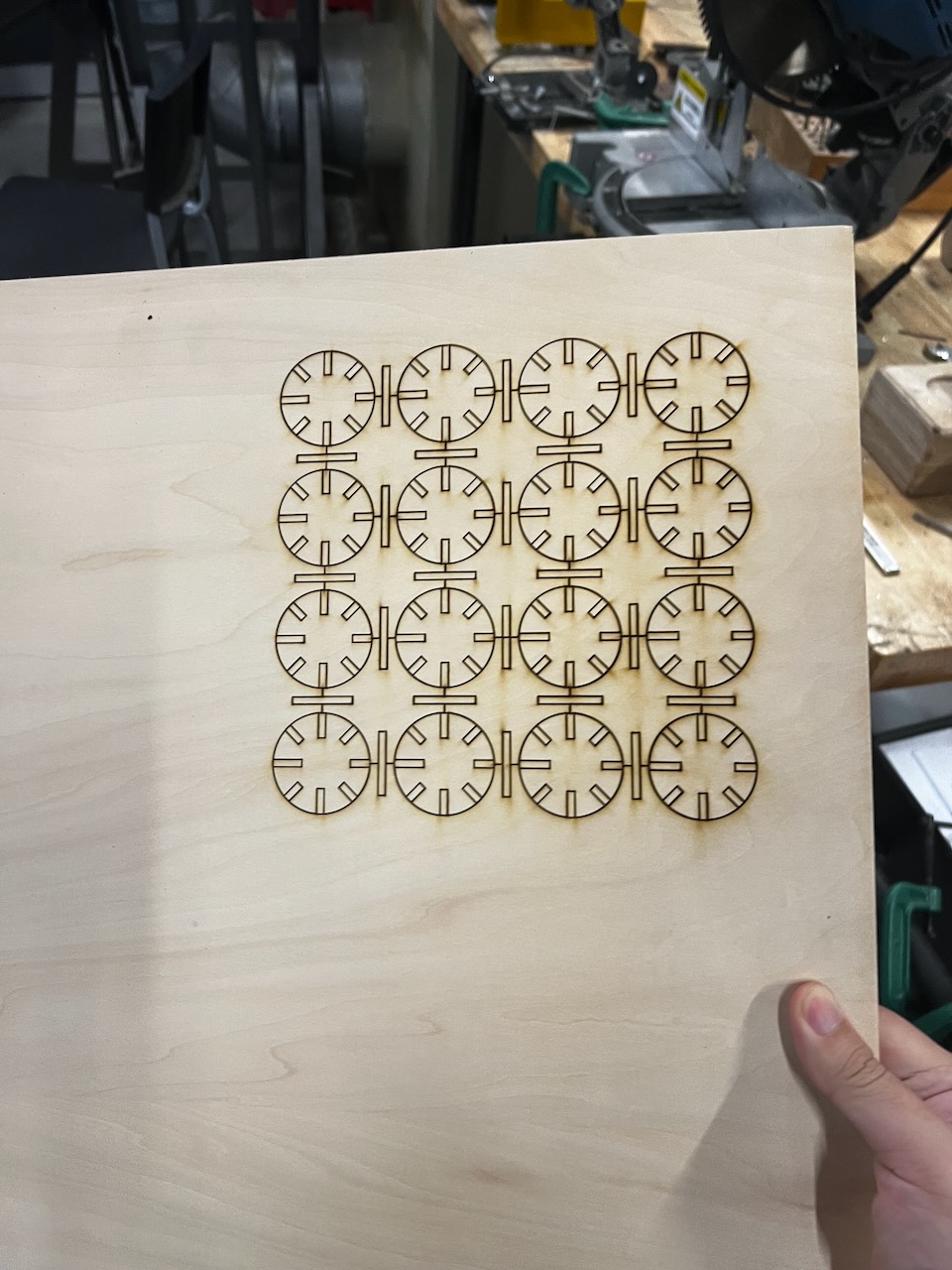
I took down these small parts and found that some were difficult to remove because the board was not flat enough, which affected the precision of the laser cutting.
Eventually, I managed to dismantle all the parts.
Results & Hero shot
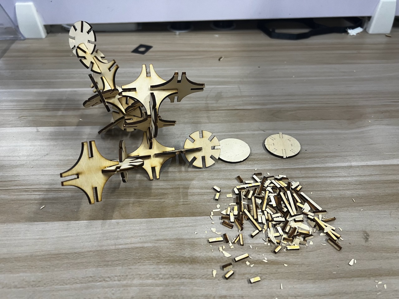
I assembled them and got the workpiece I wanted.
The issue I encountered, as mentioned earlier, was the unevenness of the wooden board, which ultimately affected the machining precision.
After assembling everything, I found that most of the parts fit together well, but a small portion was loose.
Here's my Hero shot of the parametric construction kit.
Laser Cutting--Chinese Lantern
1.The idea of Chinese Lantern
The week 3 course coincided with the Chinese Lunar New Year of the Loong.
I saw many people hanging Spring Festival decorations on the streets, among which a beautiful decoration caught my eye.
It was a piece made using cutting techniques.
So, I replicated this part, and since it's the Chinese Lunar New Year of the Loong, I also wish everyone a Happy New Year!
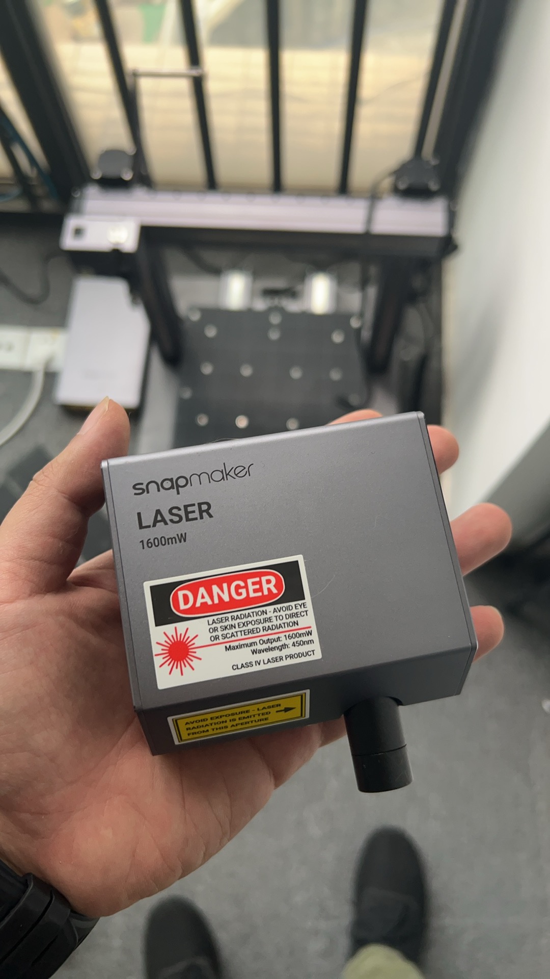
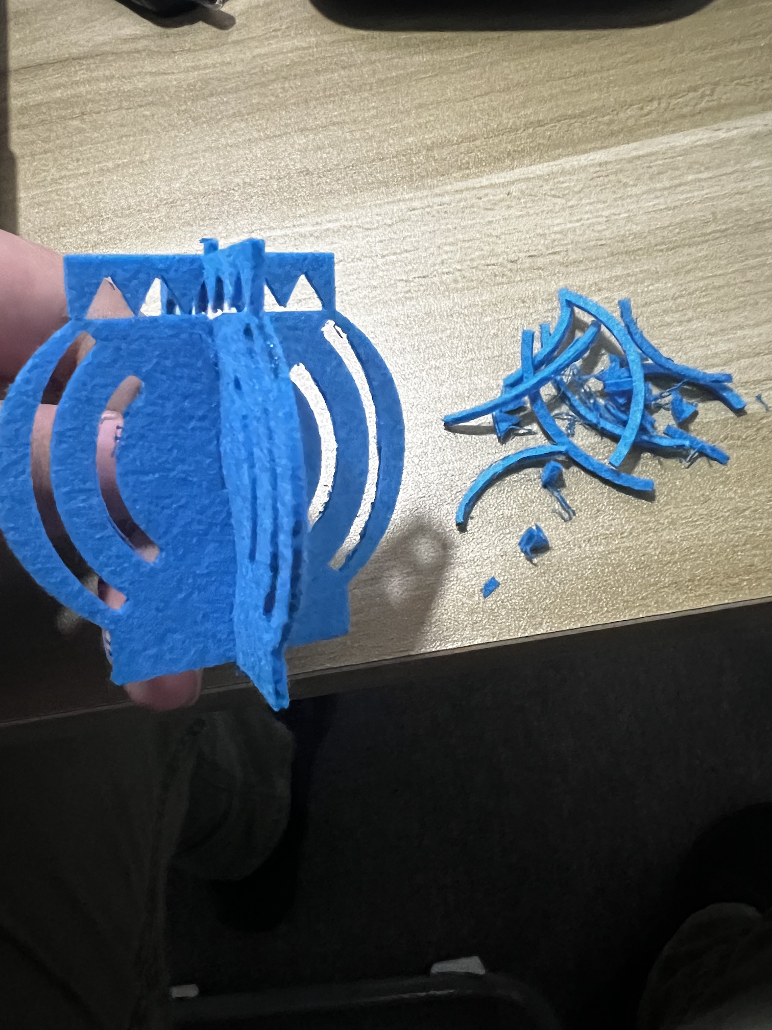
I make a Chinese Lantern in this part of assignment.

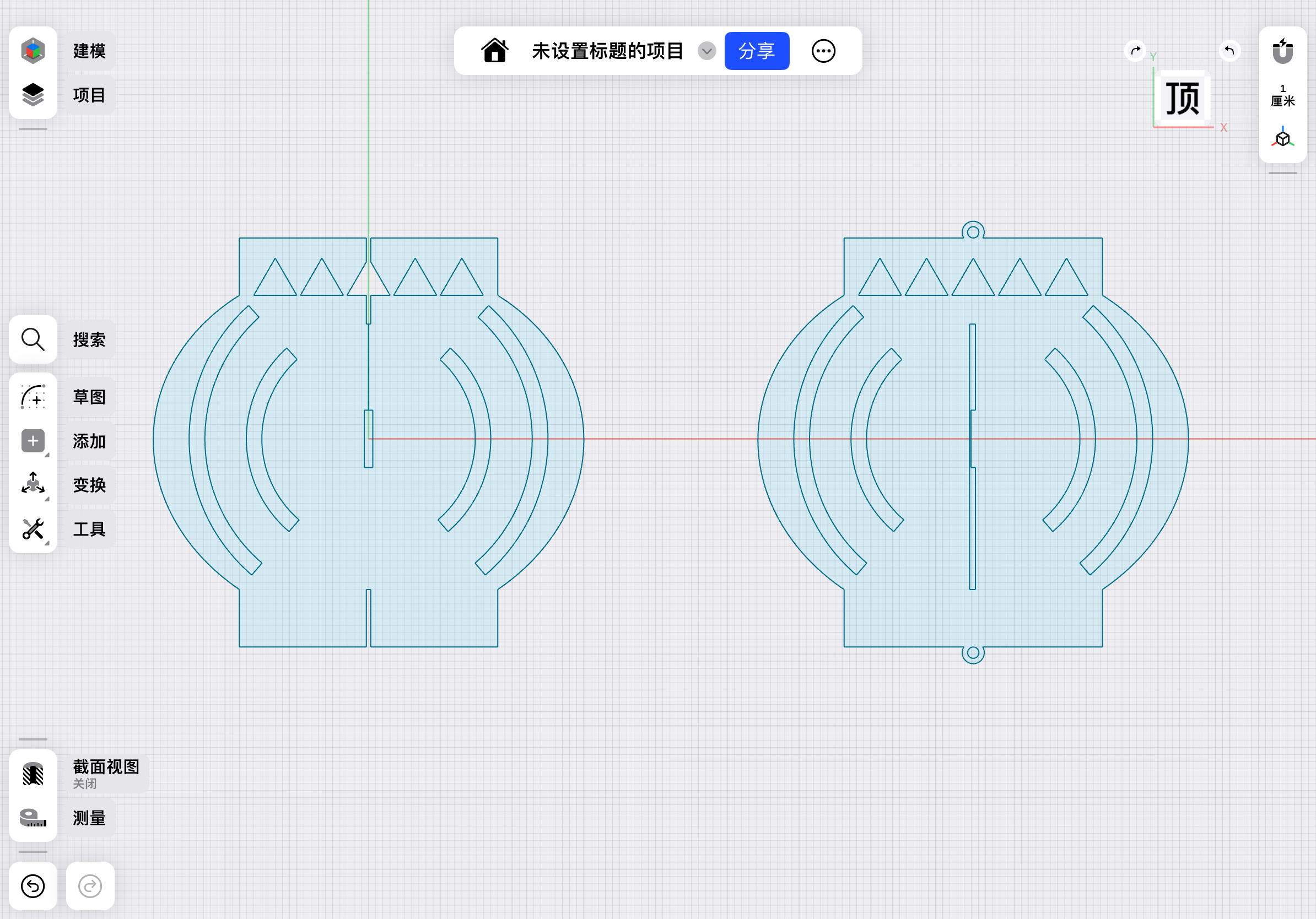
2.Create an sketch of the "Chinese Lantern"
I started by creating a sketch based on the sample I found, as shown below..
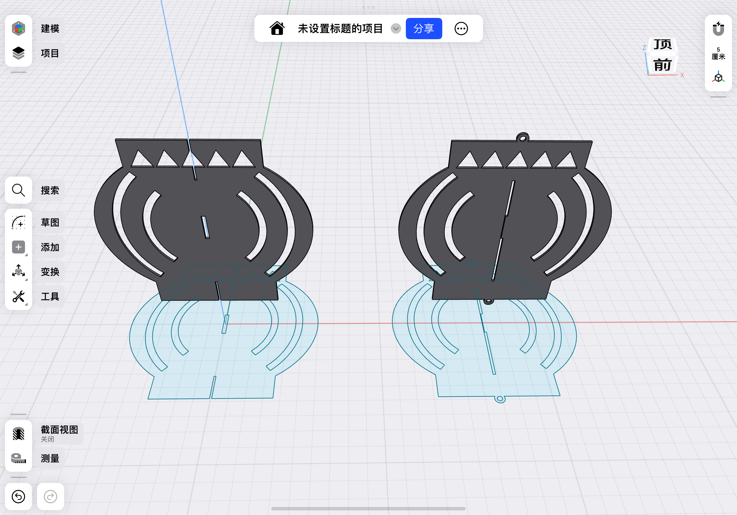
3.Solid Model Testing
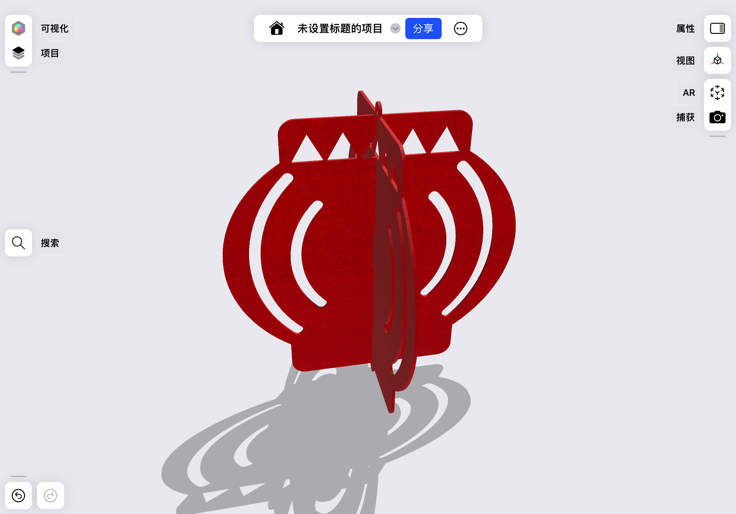
4.Decoration and Rendering
5.Exporting SVG Files and Cutting Production
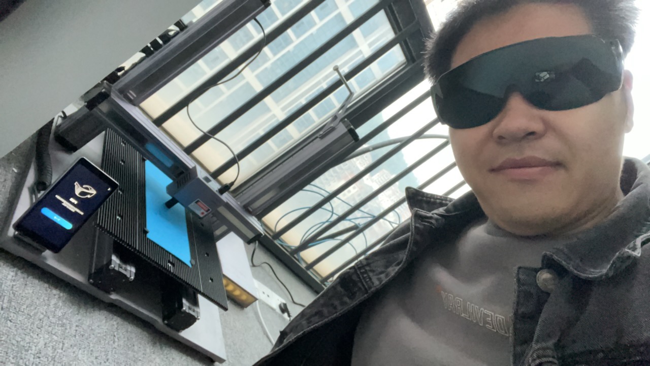
6.Setup my laser cutting machine

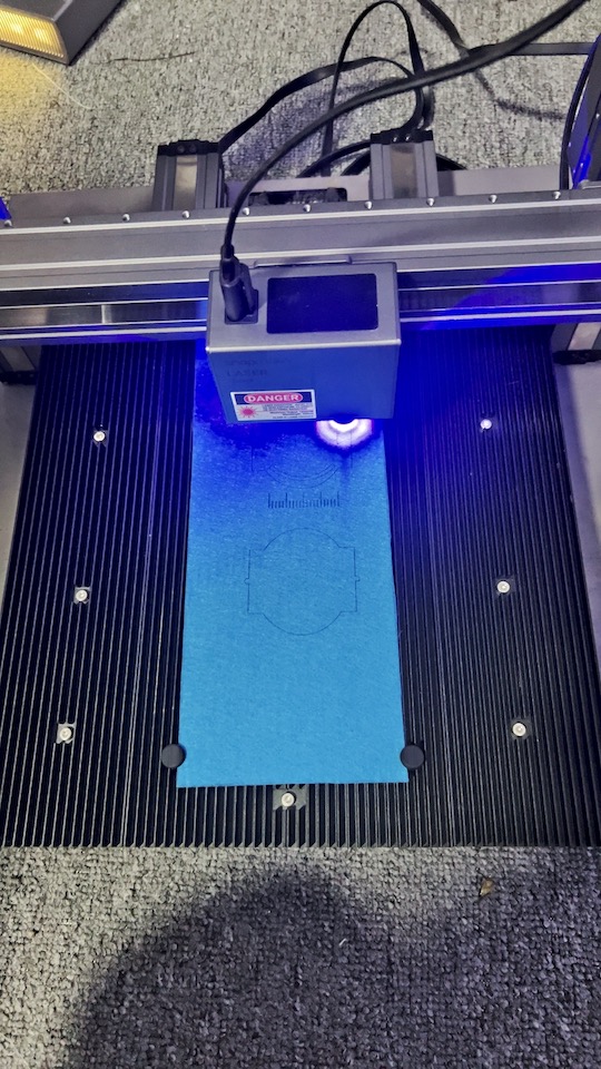
7.OK!It's time to cutting it!
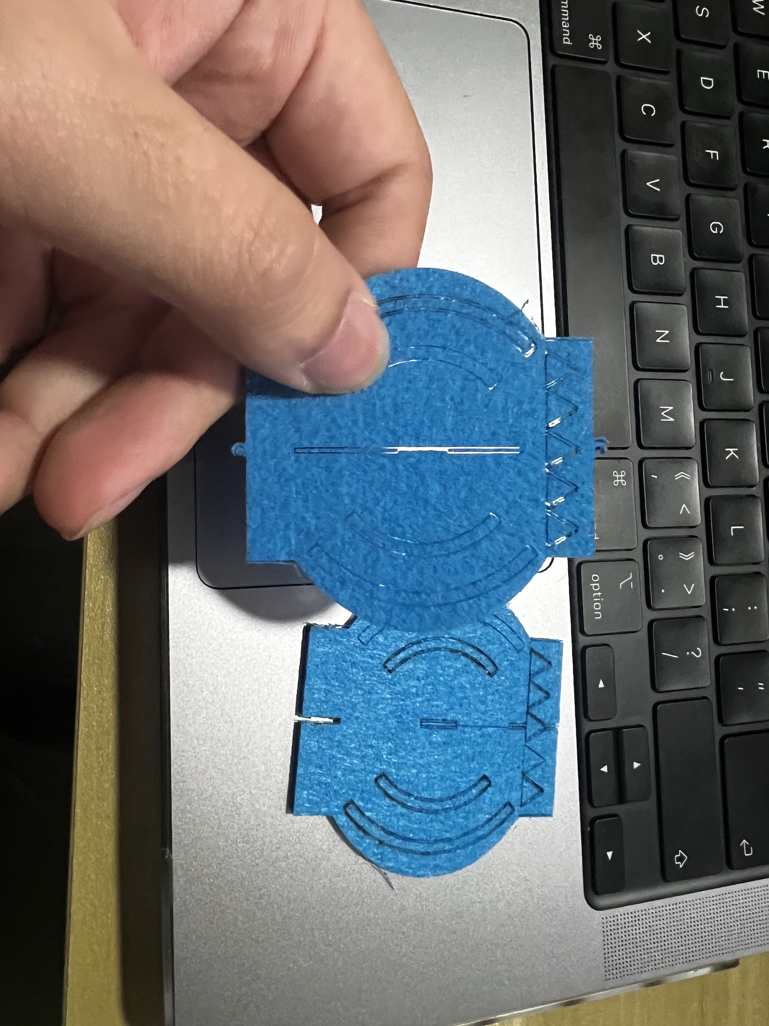
8.Get the Demo of Cutting result

9.The final step!Assemble it!
Vinyl Cutting--My FAB Sticker
1.Preparation Work
Software Introduction

Cricuit Design Space is a software that allows users to create electronic circuits using a drag-and-drop interface.
It is available for Windows, Mac, and Linux operating systems.
Here is the link to the software's manual: Circuit Design Space
Shapr3D is a software that allows users to create 3D models and animations using a drag-and-drop interface.
It is available for Windows, Mac, and Linux operating systems.
I downloaded the software from the iTunes store and installed it on my iPad.
It very easy to use and has a lot of features, including a 3D model editor, a path editor, and a rendering engine.
I just use my apple pencil to draw the designs and export them as DXF files.
Machine Introduction
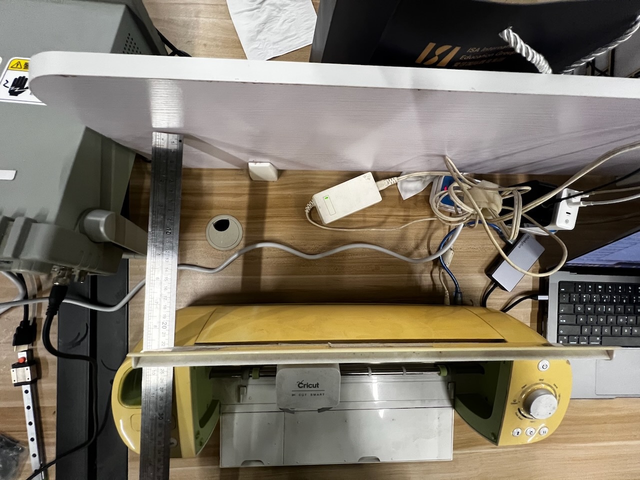
The vinyl cutter machine in Chaihuo node is Cricut Explore
I found the Safety Instructions &
Regulatory Complianceof this model, which is very important for me to follow.

2.Manufacturing Process
Design
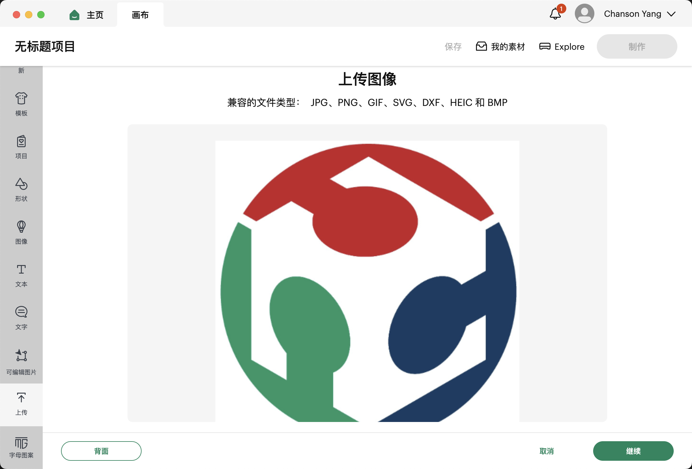
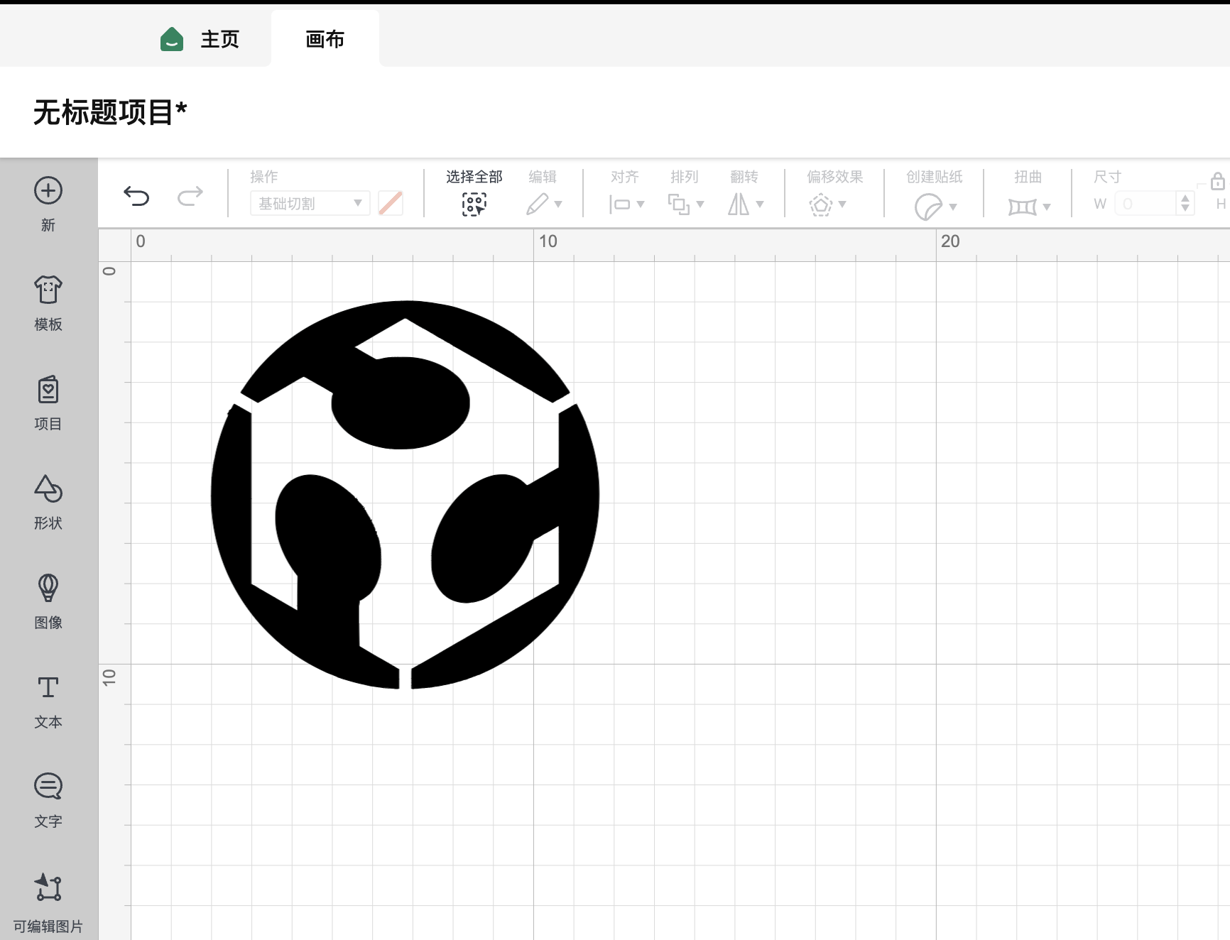
To commemorate my Fab Academy journey, I chose to cut a Fab logo.
![]()
Machining
Before machining, we need to set up the machine first.
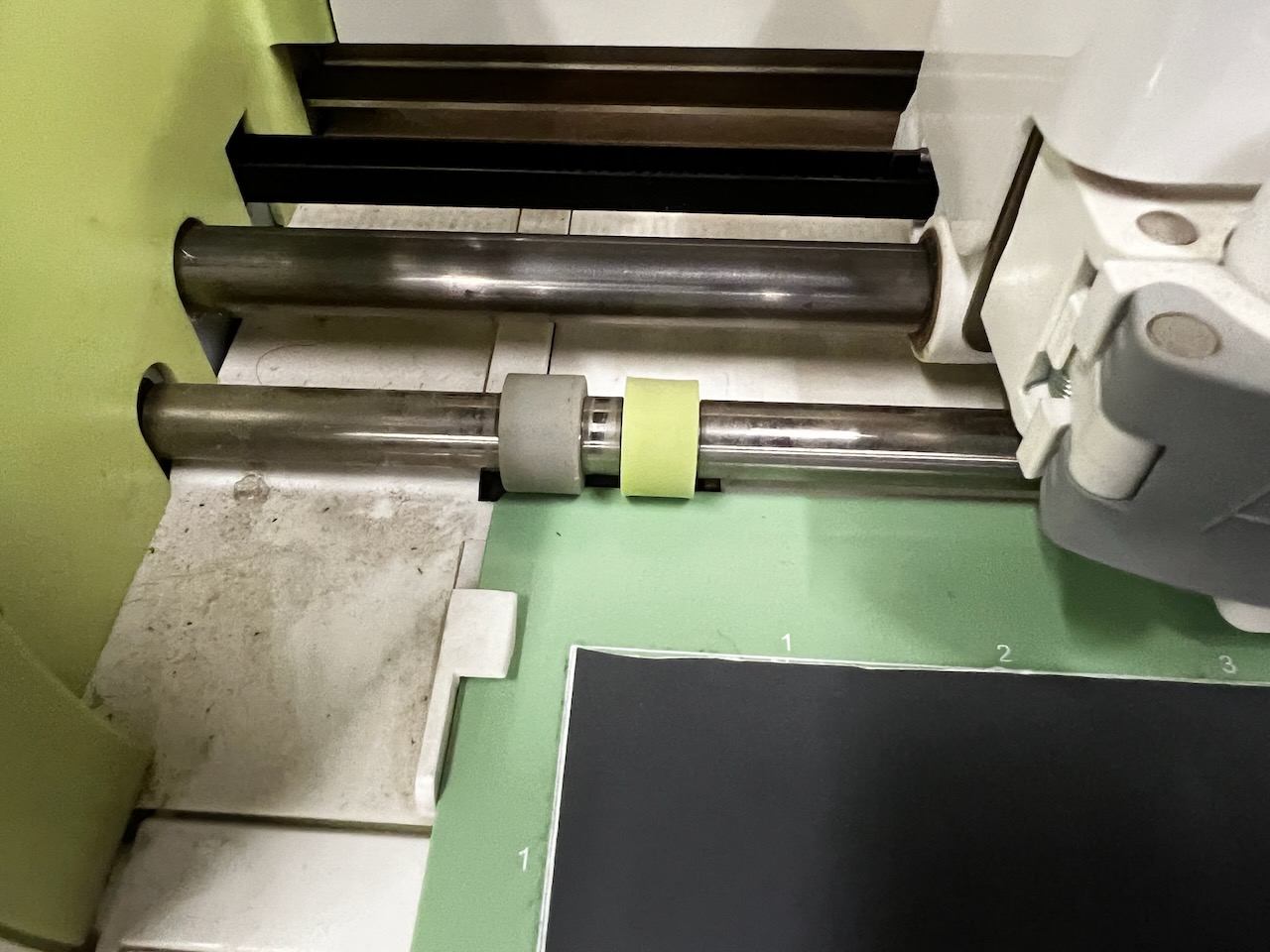
This machine requires a 20cm space at the back to ensure that the cutting panel can be output from the rear position.
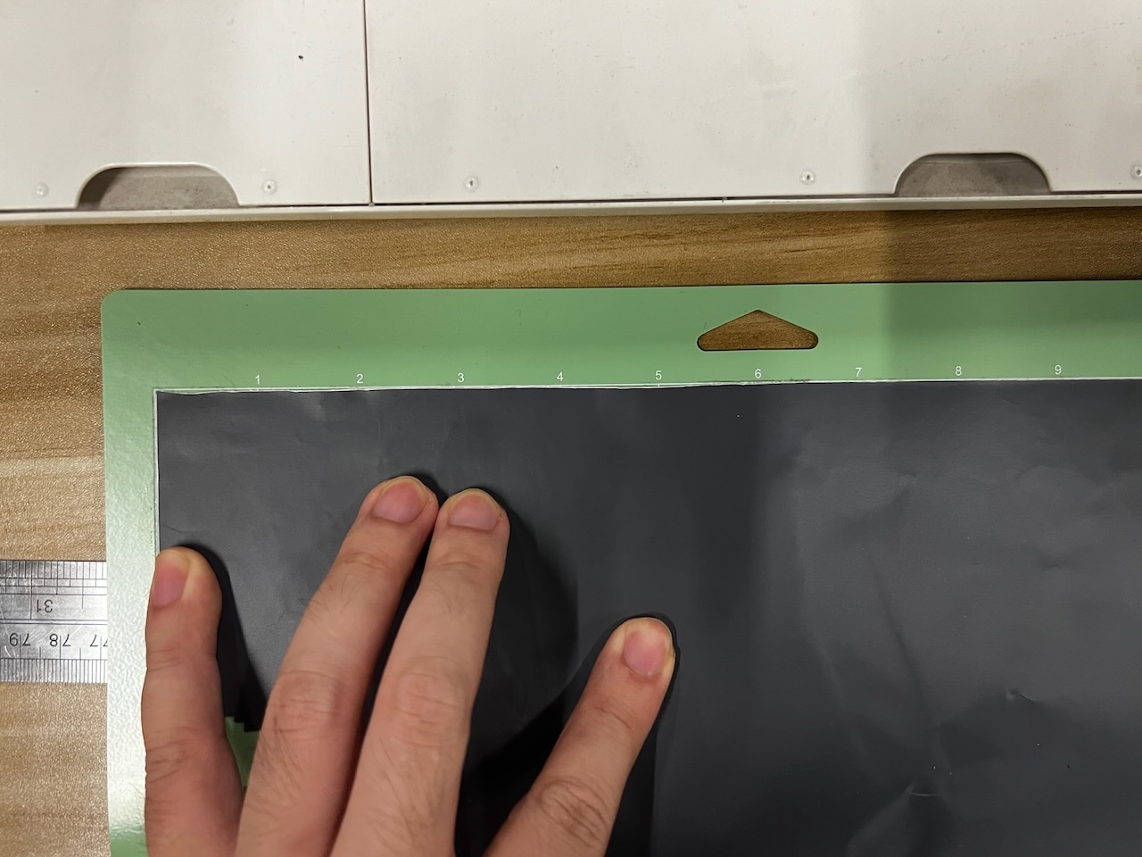
Before attempting to cut, we need to stick the vinyl paper on the machine's accompanying guide plate.
Make sure to align it properly and set the dimensions of the guide plate.
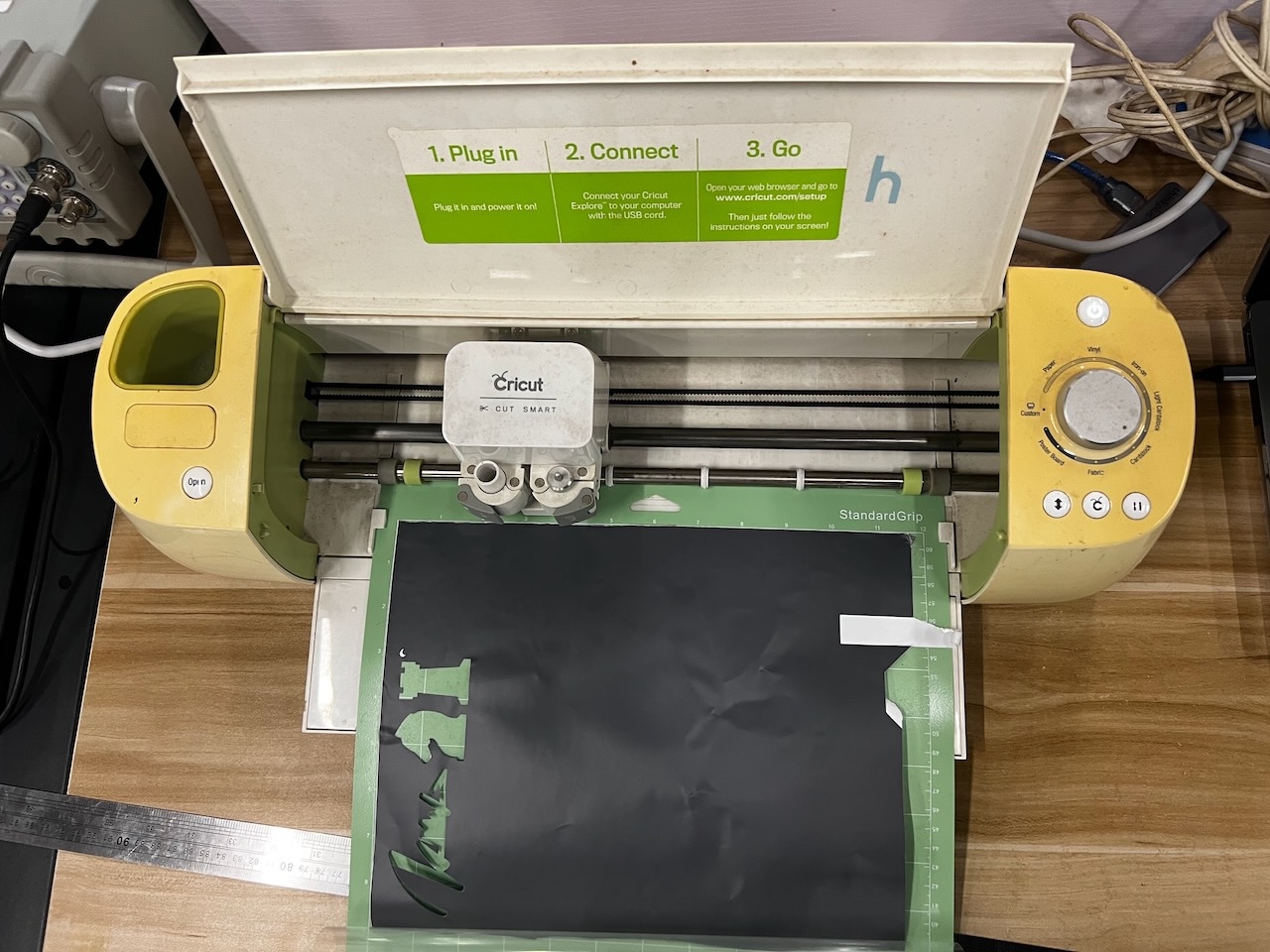
Next, ensure that the cutting tool is installed correctly.

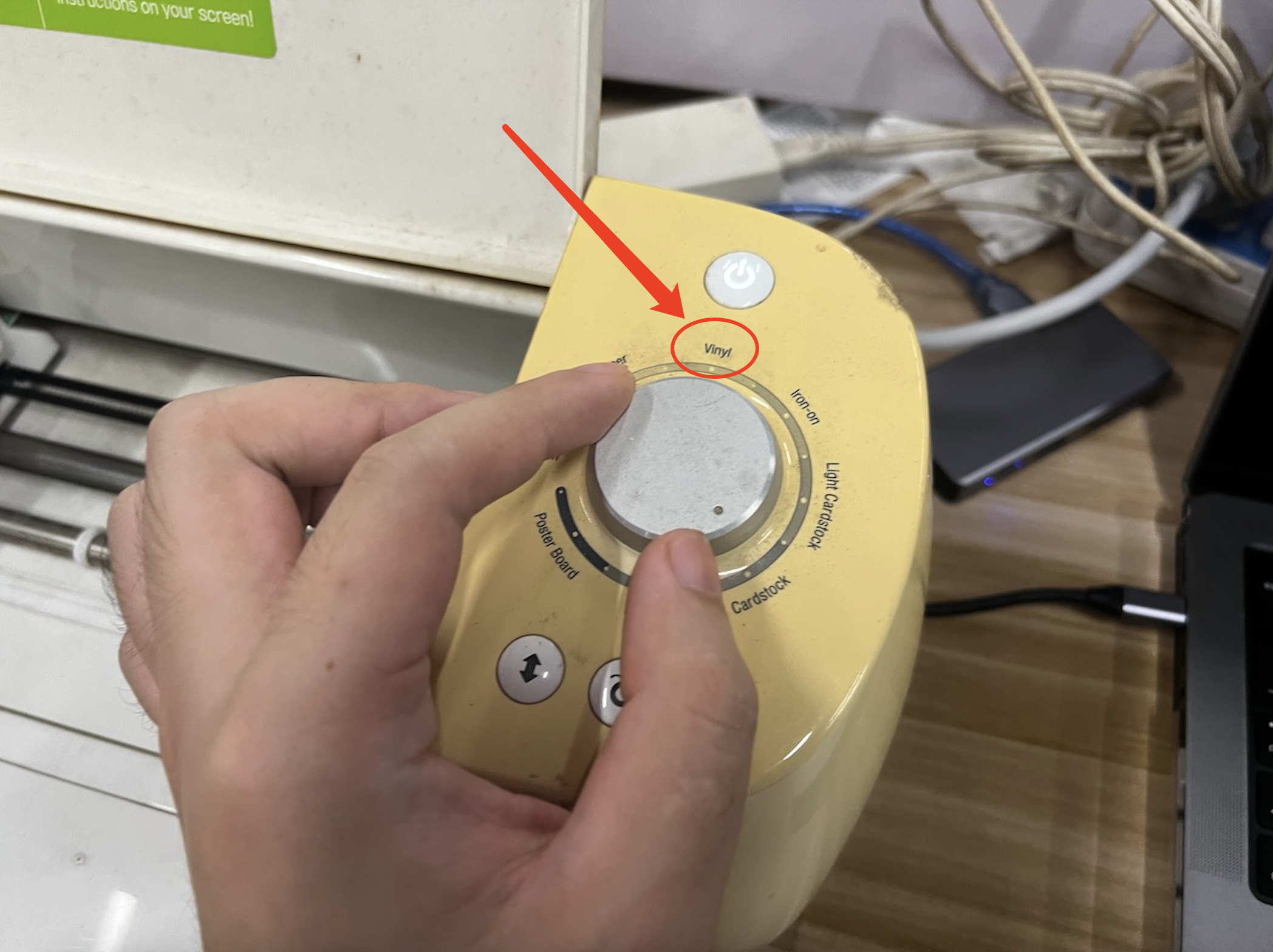
Finally, select the correct cutting material. We are using vinyl stickers, turn the knob to the corresponding option, and start the testcutting.
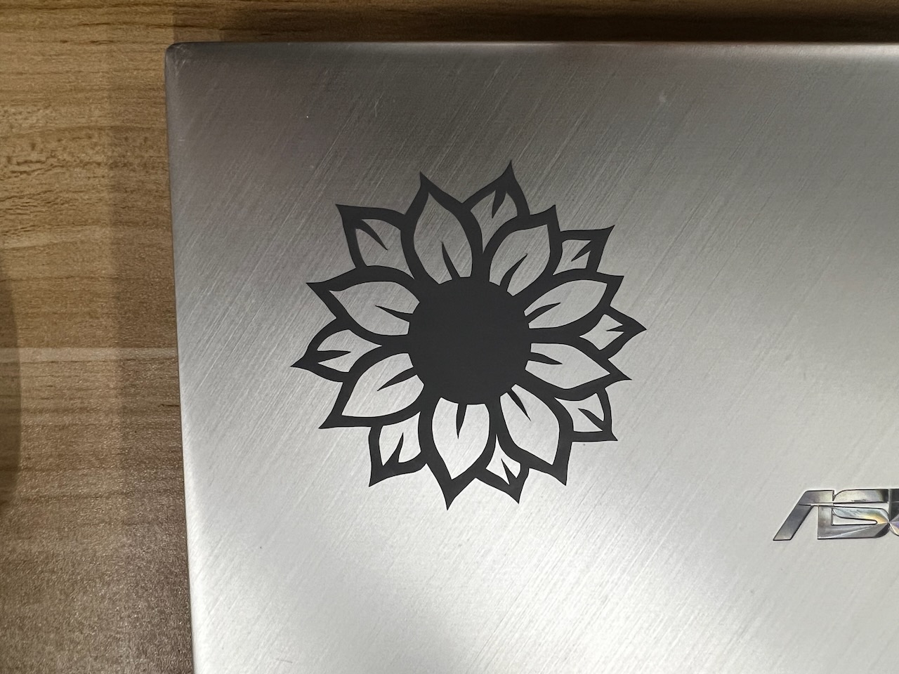
I found a sunflower pattern in the software for testing, imported the file to the workbench, and set the cutting position.
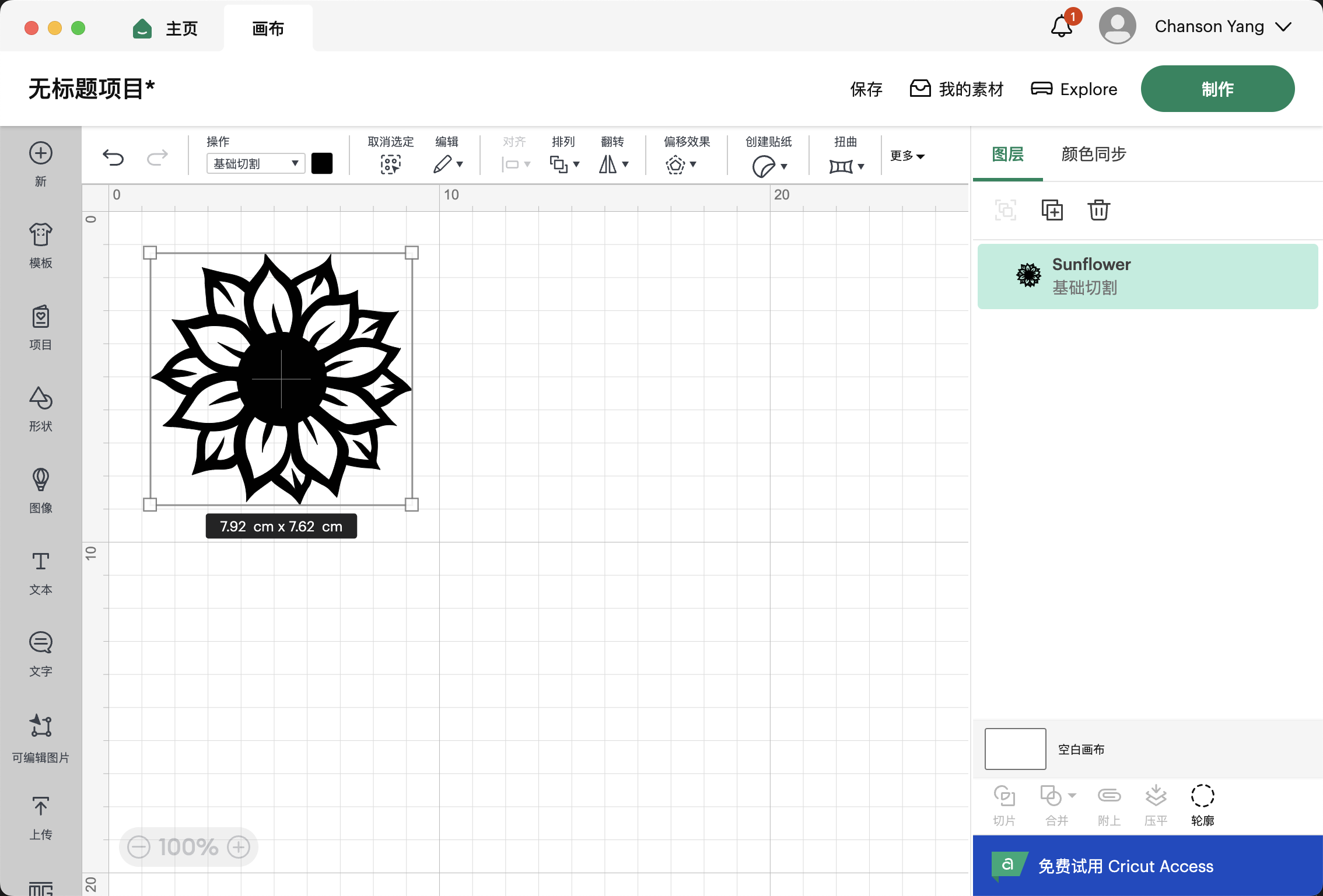
After completing the cut, I could see a very clear outline of the pattern.
Next, I carefully removed it.
My classmate Dion really liked it when she saw it, so she stuck the sticker on her laptop.

Results & Hero shot
Next, I began to try cutting a Fab Academy logo.
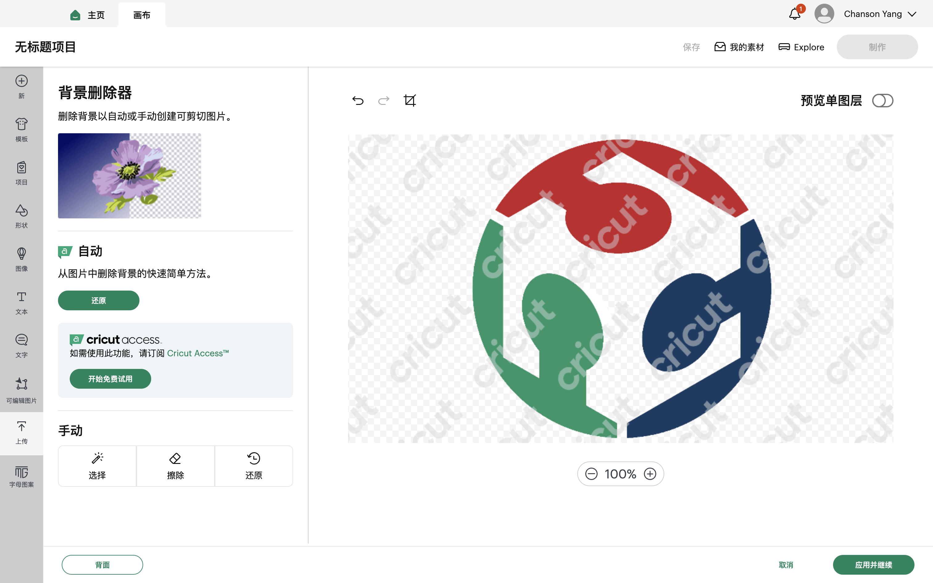
I imported the Fab logo into the Cricut program, and using the automatic background removal feature, the software removed the white background from the Fab logo.
Then, we proceeded to the next step.
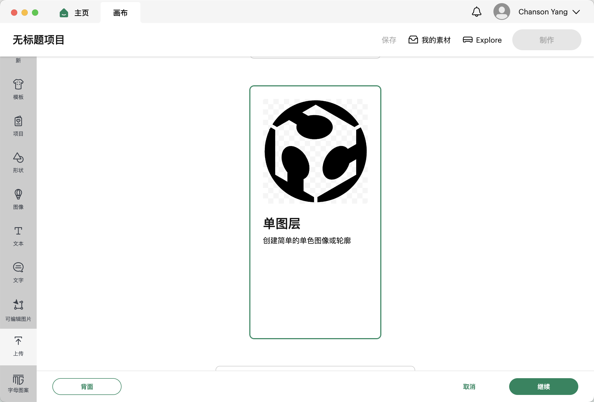
Select the correct mat; we are using one that measures 30.5 * 61 cm.
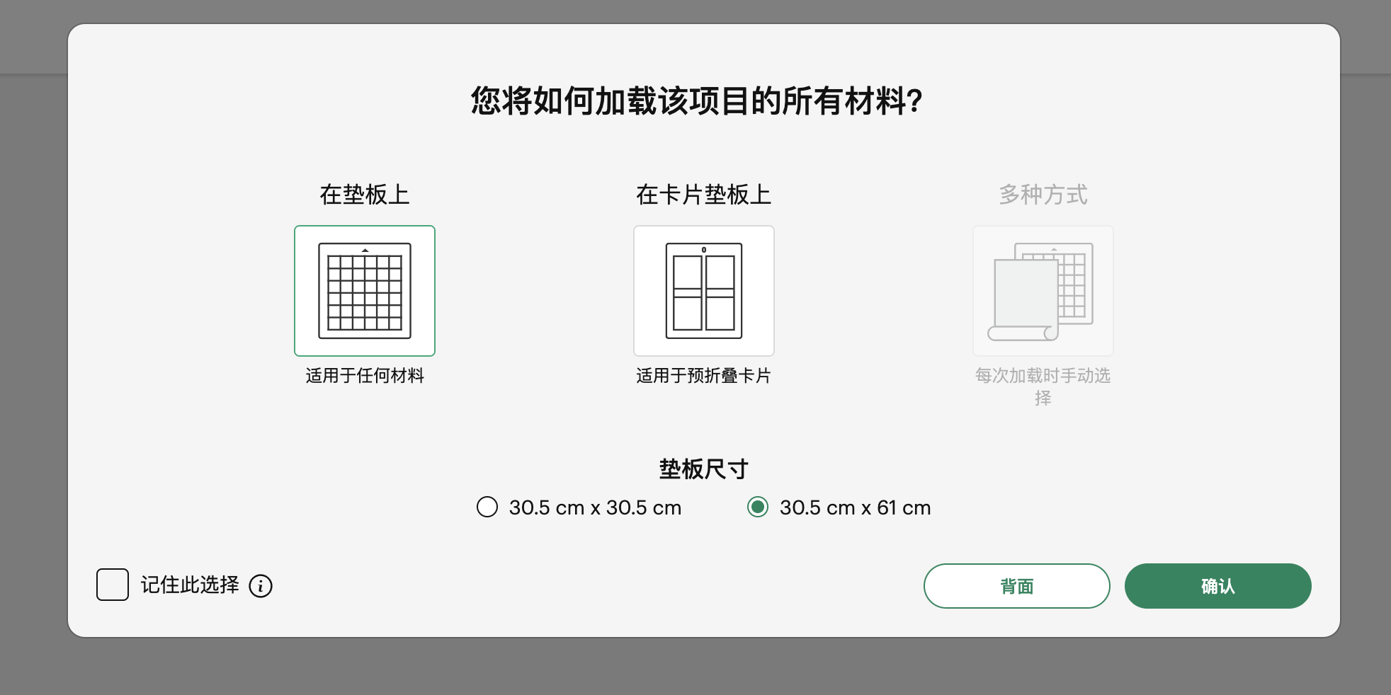
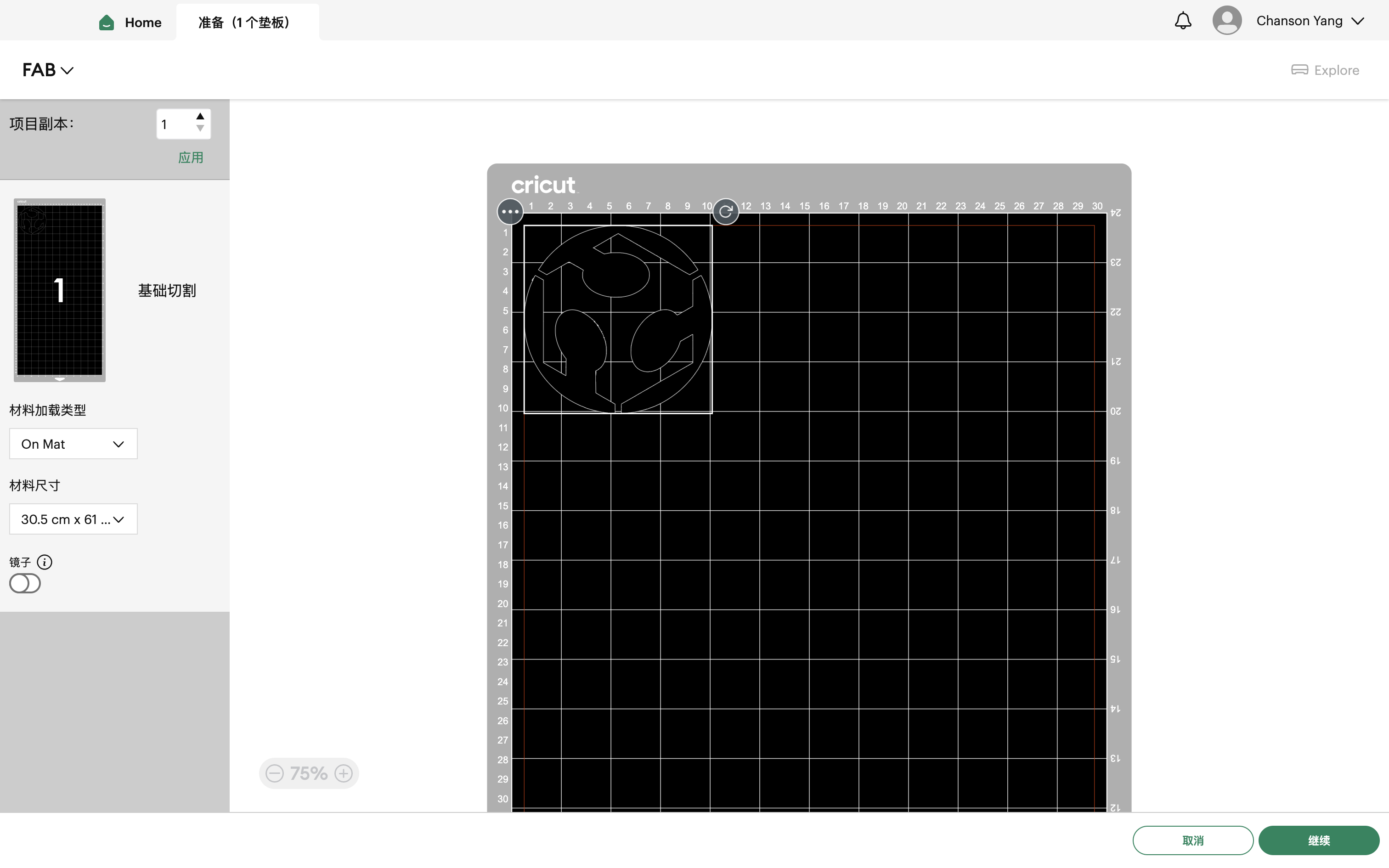
After completing the setup, we began cutting.
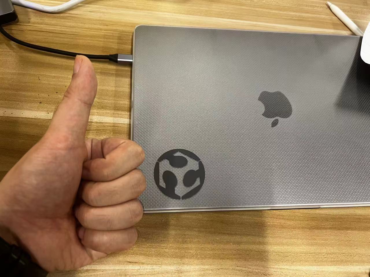
Here's my Hero shot of the vinyl cutting assignment.
Team Assignment
Laser Cutting: A High-Precision Technology
Laser cutting is a high-precision manufacturing technology that uses a laser beam to cut or engrave materials. This technique is widely used across various materials including metals, plastics, wood, glass, and fabrics. Here are some extended knowledge points to help you understand this technology more deeply:
- Laser Types: Laser cutters primarily use CO2 lasers and fiber lasers. CO2 lasers are suitable for cutting non-metal materials such as wood and plastics, while fiber lasers are particularly suited for metal materials like stainless steel and aluminum.
- Cutting Quality: The quality of laser cutting is influenced by several factors, including laser power, cutting speed, material type, and thickness. Understanding how these factors interact can help you optimize cutting parameters for the best results.
- Software and Control: Modern laser cutters are usually integrated with specialized CAD/CAM software, allowing operators to design graphics and directly control the cutting path. Proficiency in these software tools can significantly enhance work efficiency and cutting precision.
- Safety Operations: The high temperatures and potential harmful fumes produced during laser cutting require strict safety measures. Using proper protective gear, ensuring good ventilation, and adhering to operational protocols are fundamental to ensuring safety.
- Application Fields: Laser cutting is extensively used in manufacturing, art design, mechanical production, and construction. Its high precision and rapid processing capabilities make it a preferred technology for many high-end manufacturing processes.
Assignment files of Week3
Let's Jump to the Top !!!