6. Microcontrollers
This week we got an introduction to microcontrollers and embedded programming. The tasks for the week were to
- Write a program for a microcontroller development board to interact (with local input &/or output devices) and communicate (with remote wired or wireless devices) with the Seeed RP2040
- Group assignment here
Intro to microcontrollers
Many appliances you use everyday, from washing machines to cars, use microcontrollers for the various controls they have. When you use a microwave, for example, and select that you'd like to heat up your Hungry-Man frozen dinner (a product I'm intimately familiar with) and press the 1 minute button, that is sent to a microcontroller which receives the signal saying the button was clicked and subsequently sends a message for the microwave to start heating. In summary a microcontroller can receive inputs from various devices (buttons, temperatures sensors, etc...), process that information however you'd like by writing code to do so and then turning on/off other sensors and output based on those results. There are many types of microcontrollers, some that allow for more inputs/outputs (they have more "pins") and other features like built-in sensors. This week I explored these boards
- ESP32 S3 Dev on the Barduino development board
- Xiao Seed RP2040- the board we printed a PCB board for in week 04.
Programming A Xiao Seeed RP2040
As part of the task for this week I programmed the RP2040 to turn on when the onboard button is clicked and then turned it off when clicked again. As a programmer, this sounded pretty straightforward. In the Arduino IDE (what we use to send code to our microcontrollers this week) you are given 2 functions to build out.
- The "setup()" function- this is run only once and where you should initialize anything you will want to use later like pins to talk to sensors, etc...
- The "loop()" function- this is run over and over (in a loop) as long as the program is running on the microcontroller. The bulk of your program logic will likely go here where you check the status of different things you are running periodically and make updates when necessary.
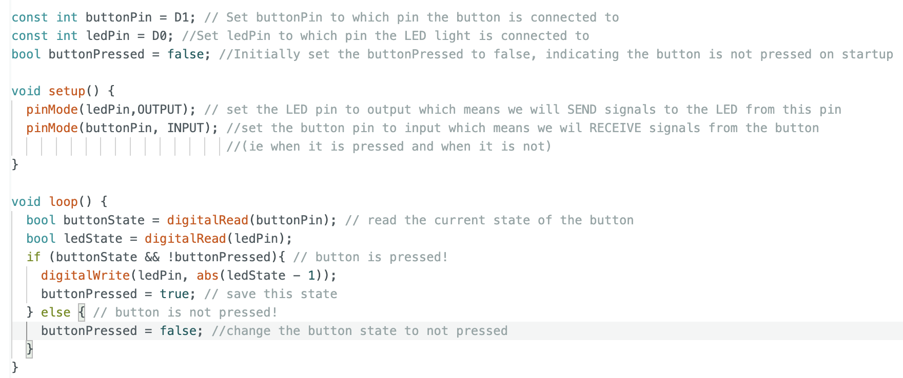
I then compiled and sent the program over USB to my RP2040. Something funky happened though. The LED would flicker and was not stable. I reviewed the code and I felt pretty confident the logic made sense. After further consideration though, I wondered if when you press the button, the circuitry doesn't just simply connect and voila. Physical things dont work so perfectly. I then wrote new code with the idea that the connection may "flicker", connect and disconnect, very rapidly. It worked! I then looked this phenomenon up and what I was doing was known as "debouncing". I then changed the name of my variables to indicate they were being used to address this.
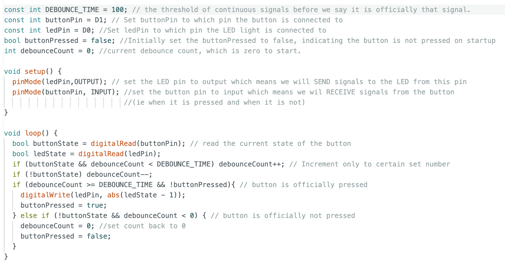
This definitely taught me a valuable lesson- in embedded programming you have to take into account how physical components actually work when you are programming and not expect things to work perfectly well.
Moisture Sensor W/ Screen
The previous week I had done some clay printing with a few other classmates. It was a romping good time but one of the very vital steps is knowing how much water to add to your clay to make it soft enough (but not toooooo soft) for the clay printer to work with. Experienced hands can tell of course. But what about a pair of novice hands (like mine) where we don't exactly have that "feel" down yet? Using a moisture reader (capacitance sensor) and a small LCD screen I figured I could make something useful for us. The wiring and instructions for both the sensor and screen were pretty well documented. But with connectivity issues, my inexperience, and an initally faulty moisture sensor I had to replace, it still took me some time to get working.
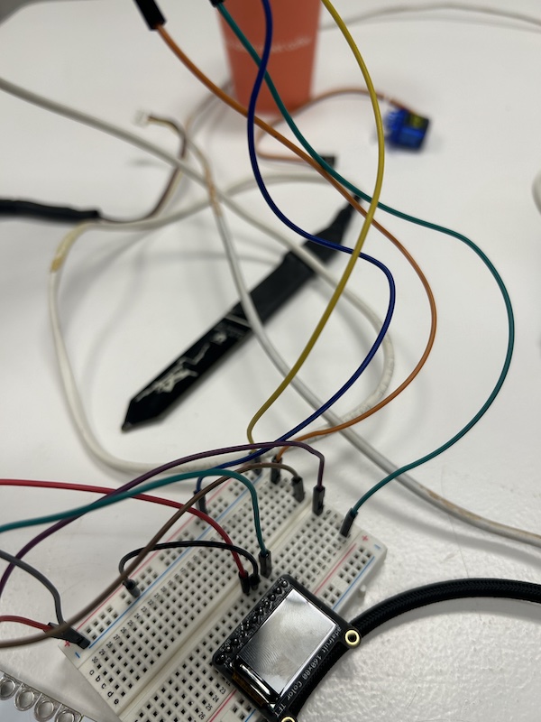
First I got the moisture sensor working with the arduino and printing to serial. Unfortunately I don't have a picture of that.
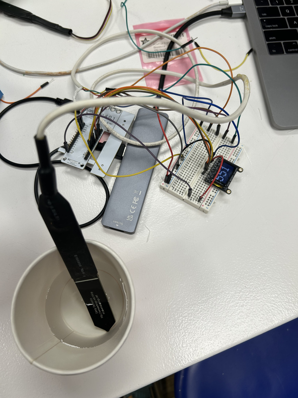
I dunked the sensor into a cup of water and looked for a change in its reading. After solving some wiring issues, I finally did get it to work! The next step was making the small LCD screen work. I ran a few basic graphic tests to draw shapes on it given by the producers of the screen. Again, this took more effort than the documentation indicate, but in the end was well explained. Ensuring you set your pins correctly and the device is receiving the voltage indicated in its datasheet are key nuggets of wisdom. Here is a picture of that initial graphics test working.
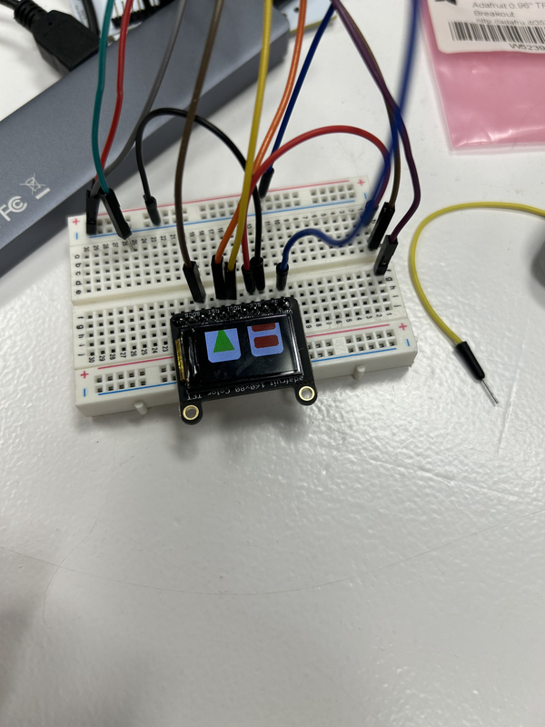
Super kul. Next step was now connecting the sensor readings to the screen. After a bit of finagling...
I had an end to end system working! Of course the reading doesn't mean all too much because we have no relative idea of what dry, wet, and just-right clay outputs look like. The next day, while my classmates made works of art, I tested their clay to see if it could discern between "good" and "bad" clay and give me a relative scale for the future.
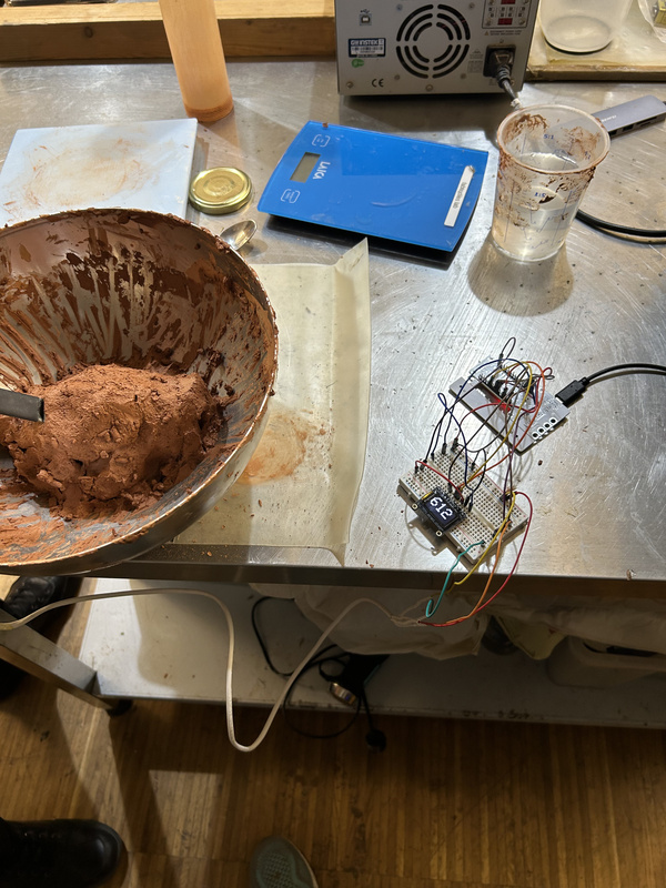
The reading was around 615-620 when I took the initial reading of the clay they were using. Later, on their second batch they ended up adding a bit more water and got a reading of ~635 as seen below.
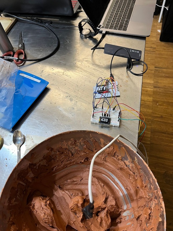
The sensitivity of the sensor is really promising! If it can discern between almost good clay and really good clay, that would be exceptional. I then tested on clay just out of the bag, with no water added.
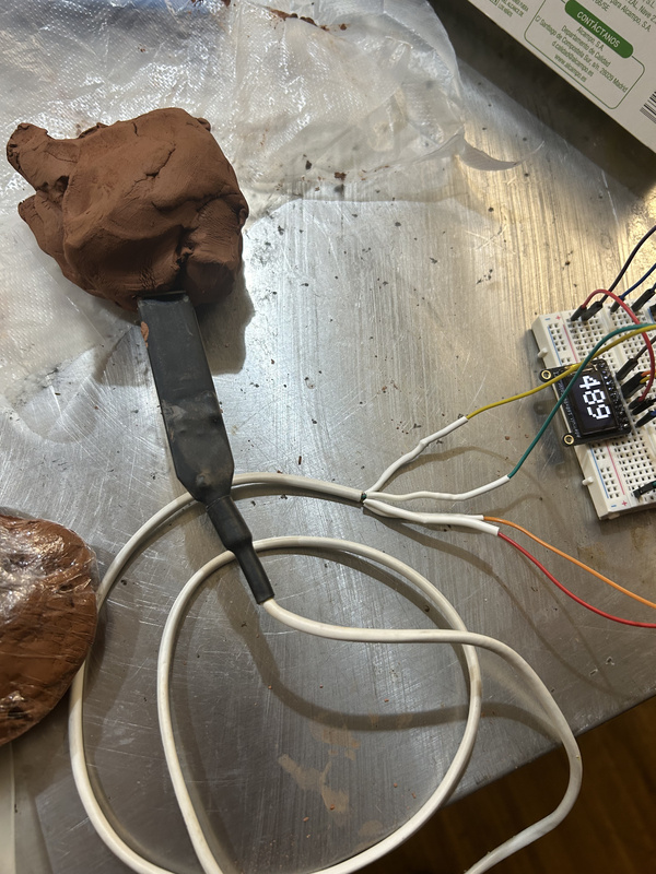
A reading of about ~490. Now I have an idea of range and ideal values. Next step would be adding a more human readable output to the LCD screen and perhaps printing a PCB board and container for the device.
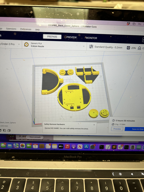
Ball and socket joint
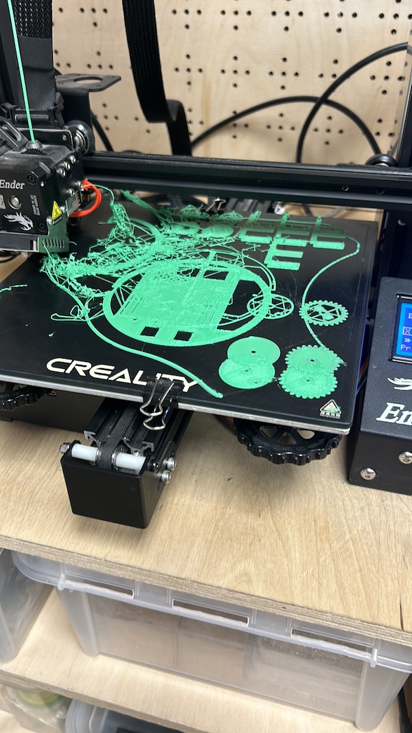
In week 5 I designed and printed a toy ball and socket joint. Max and I continued down the path of making a robotic arm, this time attempting to add servos to a ball/socket joint. Initially, we looked for inspiration for designing our own robotic joint but after some searching we landed on something too good to be denied. On thingyverse we found a really nice and simple design ready to be printed for just such a project. After looking it over we were really impressed and given our timeline it seemed like a good idea to not reinvent the wheel. We loaded up an initial print of its innards
Naturally, that ended poorly on the first attempt.
After some fiddling and reprints we finally got all of the pieces more or less looking good. The design we used didn't give a lot of information on the bolts and pieces to connect the gears and servos though so there was still quite a bit to resolve for ol Max and I. In the end we were able to piece most of it together.
As for the coding, we wrote some initial tests using serial and some basic commands ('a' to move clockwise and 'd' to move counterclockwise (or vice versa, I dont remember). After that we had planned to communicate via a python script with a simple GUI to send commands to the robot. More on that script can likely be seen on Max's page.
Our first nearly assembled test didn't quite go as planned. We realized the gears were not quite bolted on firmly enough to work properly.
You can see in the video that the gears worked properly in one direction but not the other. After max worked on tightening up certain areas with better fitting bolts and some nuts, we once again ran a test with more consistent results
Unfortunately though, we have not quite finished and need to reprint the gears to be a bit better fitting as they still don't consistently catch. We hope to have a working model in the next couple of days to continue on the journey of making a robotic arm that can do our bidding.
Lessons learned
- Even if the progamming logic can seem relatively simple the small uncertainties of hardware can make things trickier than they seem. Always write your program with that in mind otherwise you're in for a world of hurt.
- There are a lot of great designs out there that probably almost do what you'd like. Don't ignore those.
- Test your project piecewise rather than all at once. I've learned time and time again that this will end up saving you a lot of time in the end.
- Ensure that all your wires are properly plugged in if you are using a breadboard. Again, not checking can lead to a lot of heartache.