4. Electronics Production
Project Overview
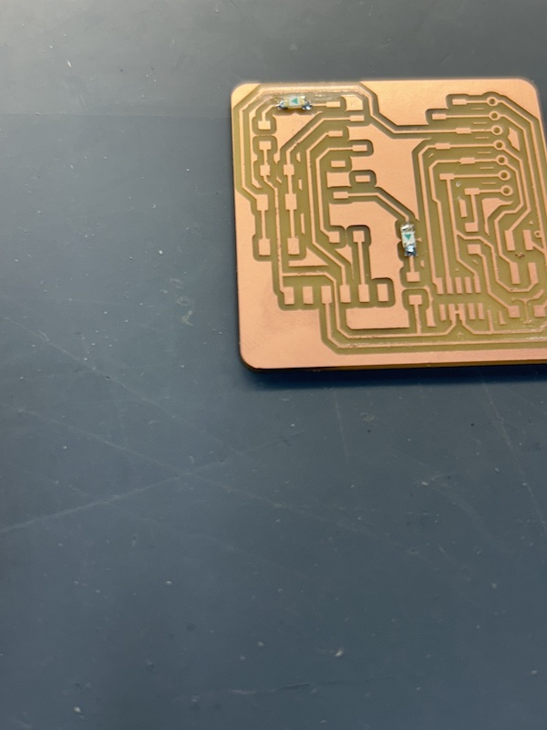
The goal was to create a Quentorres programmer using a Seeed RP2040 microcontroller first by milling a printed circuit board (PCB), and then soldering on the required surface mount electronic components (LEDs, resistors, etc...)
Here is a link to the group assignment!
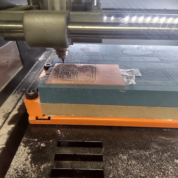
Milling Process Summary
For this task, we used FR-1 PCBs. They are the board of choice because they are non-toxic, have nice mechanical strength, and are flame-retardant (which is nice, unless you're cooking), and low cost. This site says it better than I will. The milling process takes off the top layer of copper in areas that are not a part of the circuit, basically working on the negative/backgorund portions of the circuit design. All areas that should be connected are then surrounded by a non conductive material, providing a buffer between the circuitry and any remaining surface metal on the board. This means that there may be copper left over in areas that are not actually part of the circuit, but they are not connected to the circuit itself. The figure below does its best to describe that.

Important Milling Takeaways
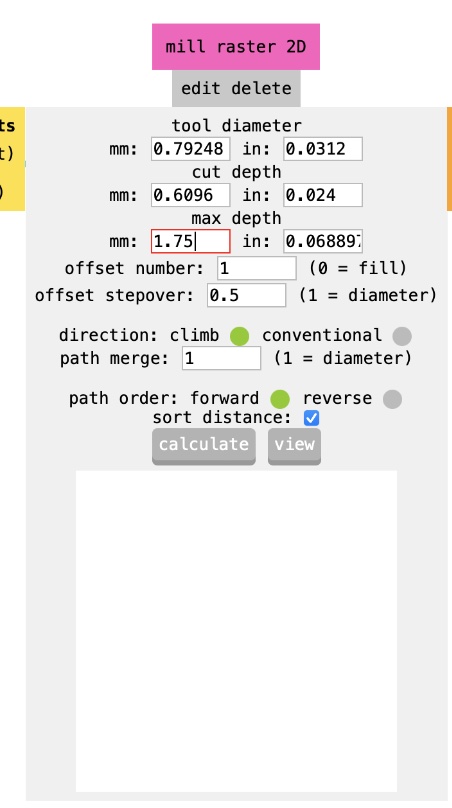
- Used modsproject.org to prepare the file the milling machine software would use. It basically takes a PNG of the circuit and given a few baseline parameters like mill size, origin location, etc.. does the rest.
Ensure cutting coordinates are always 0,0,0 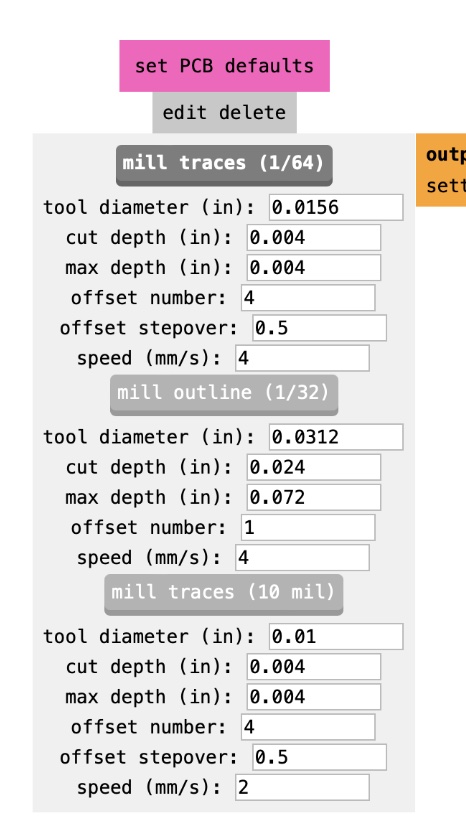
Ensure Z Jog height is > 0 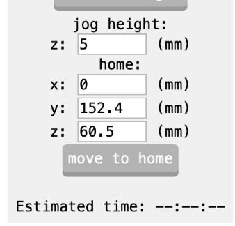
Turn on saving to file 
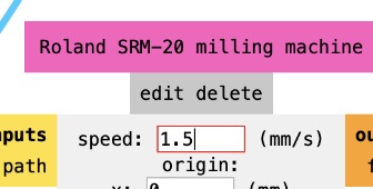
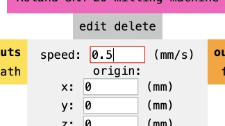
- Using a precision milling machine, we employed 2 flat end mills, 1/32 and 1/64 of an inch. The 1/64th inch mill is used for the tracing step and it requires finer grained cuts.
1/64 inch setting for traces
Speed for traces (3.5) 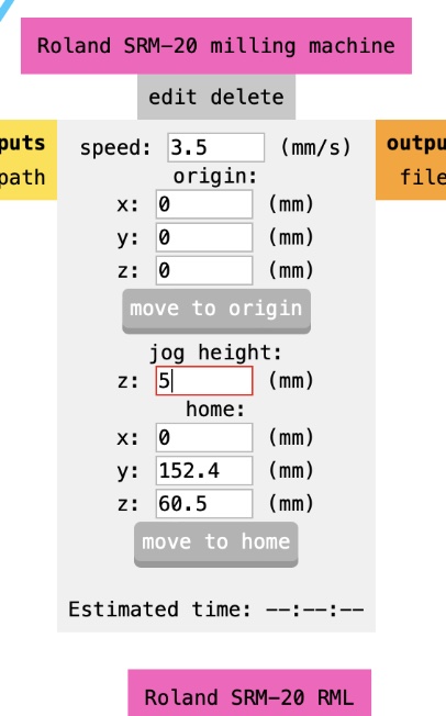
- The 1/32nd inch mill was used for both hole cutting and actually cutting out the resulting board. We also change the final height to 1.75 mm to not cut too much through the sacrificial board beneath our PCB
- While tracing, an "offset" is used which is basically how much padding to give between the circuit's wiring. This is important to be mindful of because if the offset is too small compared to how finely the mill can cut, you may end up with copper connecting where it shouldn't (short circuit). On the other hand, increasing offset will increase the required board size and may waste material.
- Order mattered! First you trace the circuit, then make the holes, then cut out the board.
- Keep the board flat and true.
- Be careful with the 64th inch mill. It's really fragile.
Soldering.
First thing I had to do was find the components to solder to the Quentorres board. Those are specified here. The only component I had trouble finding were the blue LEDs. I was later chastised for using red ones in their place at the advice of my beloved instructor, Adai. A lesser man would blame Adai for this and he would be completely justified. I, however, am willing to shoulder the responsibility of the error in spite of it being mostly (if not completely) Adai's fault.
Finally, the meat 'n potatoes of the operation. The soldering. The first thing I noted was the size of the components. They were very small, which was worrisome. Given the very little experience I had and clumsy nature of my hands, things did not go smoothly. Against the advice of the instructors I put the solder directly on the on the hot soldering iron. I also used gobs and gobs of solder. I wanted to make sure the piece stayed connected. I wanted to be safe, I thought. But more is not always better as anyone who has been to a dumpy all-you-can-eat restaurant can tell you (sorry Old Country Buffet, I actually did love you.). Eventually I managed to finish my first board and after loading a small LED blinking program on it, it blunk! In spite of my best efforts to sabotage my board, it worked.

As I laid awake that night at 2am with a feeling of deep dissatisfaction, I knew I had to make another board. After looking at my classmate, Emily, solder I realized I was making several mistakes. She also gave some very helpful tips. This time I'd do it right I told myself. The next morning I went in and milled another board. When soldering time came I was bright-eyed and bushy-tailed. I began by grabbing the correct, blue LEDs. Adai was not present. Things started off rough though. I couldn't seem to get the first LEDs flush on the board when soldering. I went to Josep and asked what he thought of my initial issues. He readily pointed out that I had managed to solder them in upside-down.
He then proceeded to tell me I was the first person to ever do that in the lab! Did I detect a hint of admiration in his tone? I'd like to believe so. Finally, I went back with regained vigor, removed the incorrectly oriented LEDs. After paying attention to touching the copper and the pins of the component with the soldering iron, and not the solder directly, things went much smoother. I also checked for appropriate connectivity periodically with a multimeter. After that, I tested the blinker program and well, she blunk. The End.
Here is my blinking code.
Lessons Learned
- Touch the soldering iron to the copper, not directly to the solder, for proper solder flow.
- Ensure LEDs are correctly oriented.
- Use a multimeter to check for unwanted connectivity after manual adjustments.
- Removing components can be good practice for learning to correct mistakes.
- Practice and patience are key to improving soldering and milling quality.