Week 7
Computer-controlled Machining
Fab Academy 2024
Riichiro Yamamoto
- Group Assignment
- Make Something Big
- Test 1
- RhinoCAM
- CNC Milling
- Test 1 Result
- Test 2
- CNC Milling
- Chair
Dear My Friend
This week was another fun-making week. I had a lot of fun working with the CNC milling machine. I have done CNC milling before but the controlling of the milling machine part was done by a technician in the workshop. So it was the first time for me to actually use the machine and do the all settings by myself. This week we were limited to only milling in 2D, but I am looking forward to do 3D milling in the coming week.Hope you enjoy
Riichiro Yamamoto
Group Assignment
this week's group assignment was to do your lab's safety training test runout, alignment, fixturing, speeds, feeds, materials, and toolpaths for your machine.
Here is the link to the group assignment page
Make Something Big
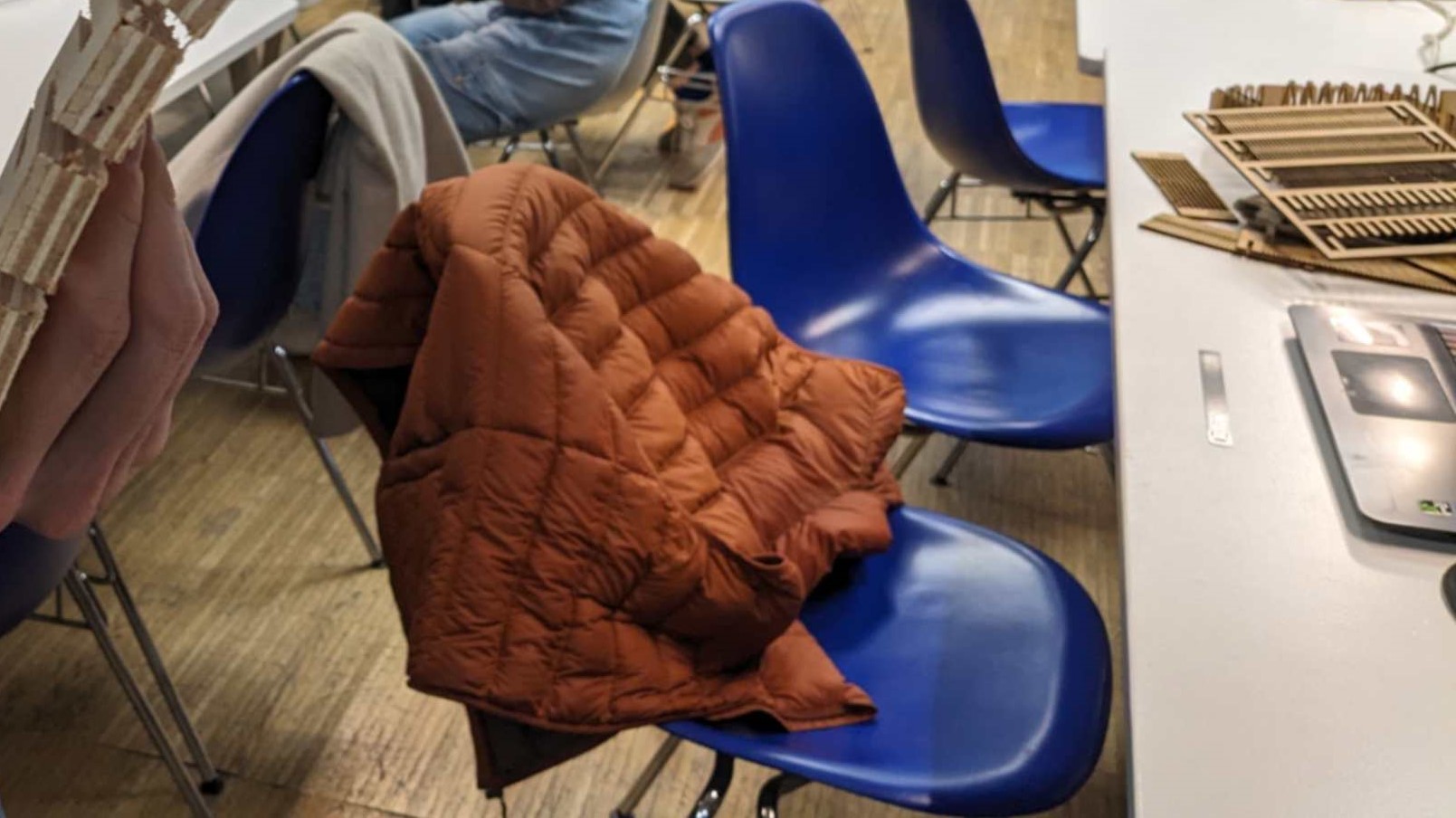
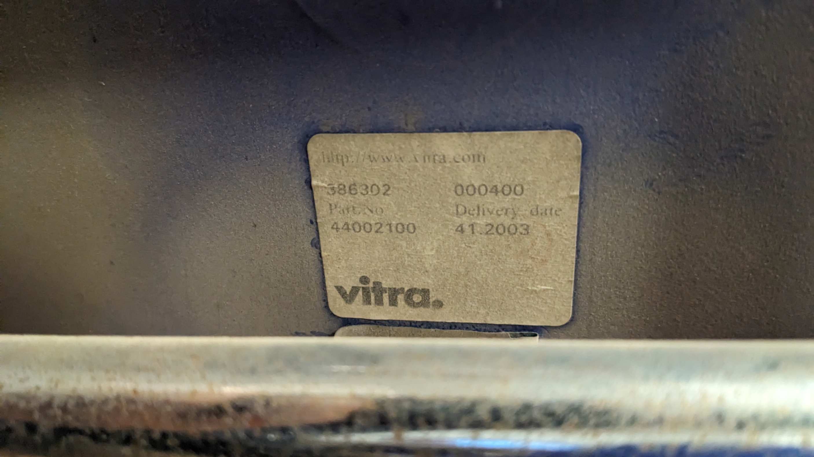
This week’s assignment was to make something big (around 1m scale) using a CNC Milling machine. I decided to make a chair. As a reference, I used a chair in which I was sitting in our lab. It is an Eames Plastic Side Chair RE DSS made by Vitra. From the Vitra website , I was able to get a 3d model of the exact chair.
FilesEames_Plastic_Side_Chair_DSS_3D.dxf
/jpeg-optimizer_01_EamesChair_01.JPG)
Modelling
By deconstructing the 3d model, I started to understand the structure and assembly. To get the shape of a sitting part of the chair that fits our body. I cut a section of the chair in the middle using a Clipping Plane and traced the curve. Also, I took basic dimensions from the 3d model to use for my chair.
Files
00_CNC_Main.3dm
/jpeg-optimizer_01_EamesChair_02.JPG)
/jpeg-optimizer_01_EamesChair_04.JPG)
Test 1
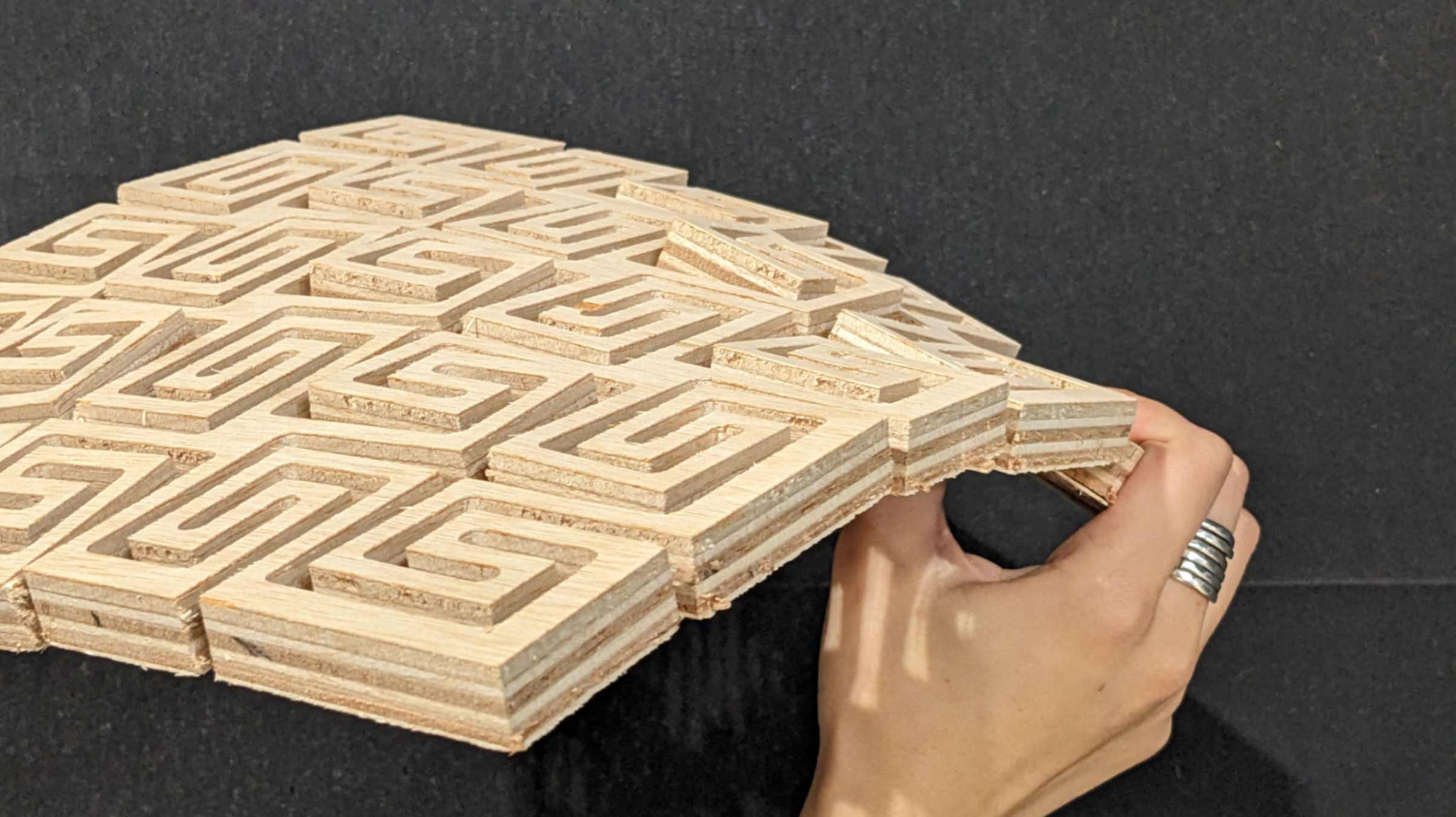
Since the chair has a curved surface, I needed to find a way to remake it by using CNC milling. To do that, I thought the Living Hinge and Double Curvature that I tested in the Computer Controlled Cutting week (Week 3), would be a good test to see if I can achieve similar functions by CNC MIlling.
Because both Living Hinge and Double Curvature require dense patterns, I needed to consider the diameter of the drill. The pattern I used for laser cutting did not leave enough area for connection, so I scaled it up to make it suitable for CNC milling. From the previous experiment with Laser cutting, I had a general understanding of the design rule for Living Hinge and Double Curvature, so I knew it would become significantly fragile when the thickness of connecting parts is thinner than the gap.
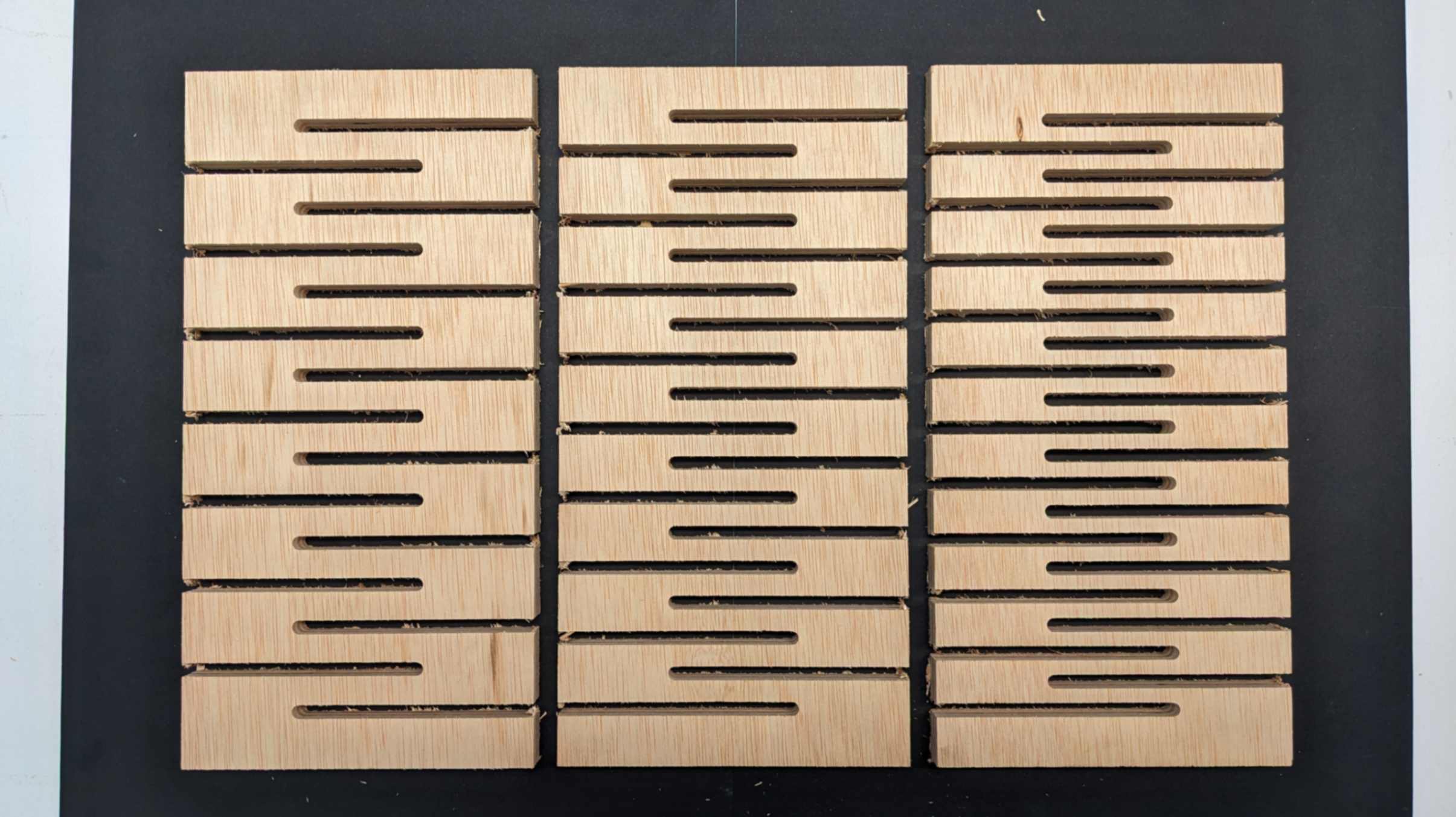
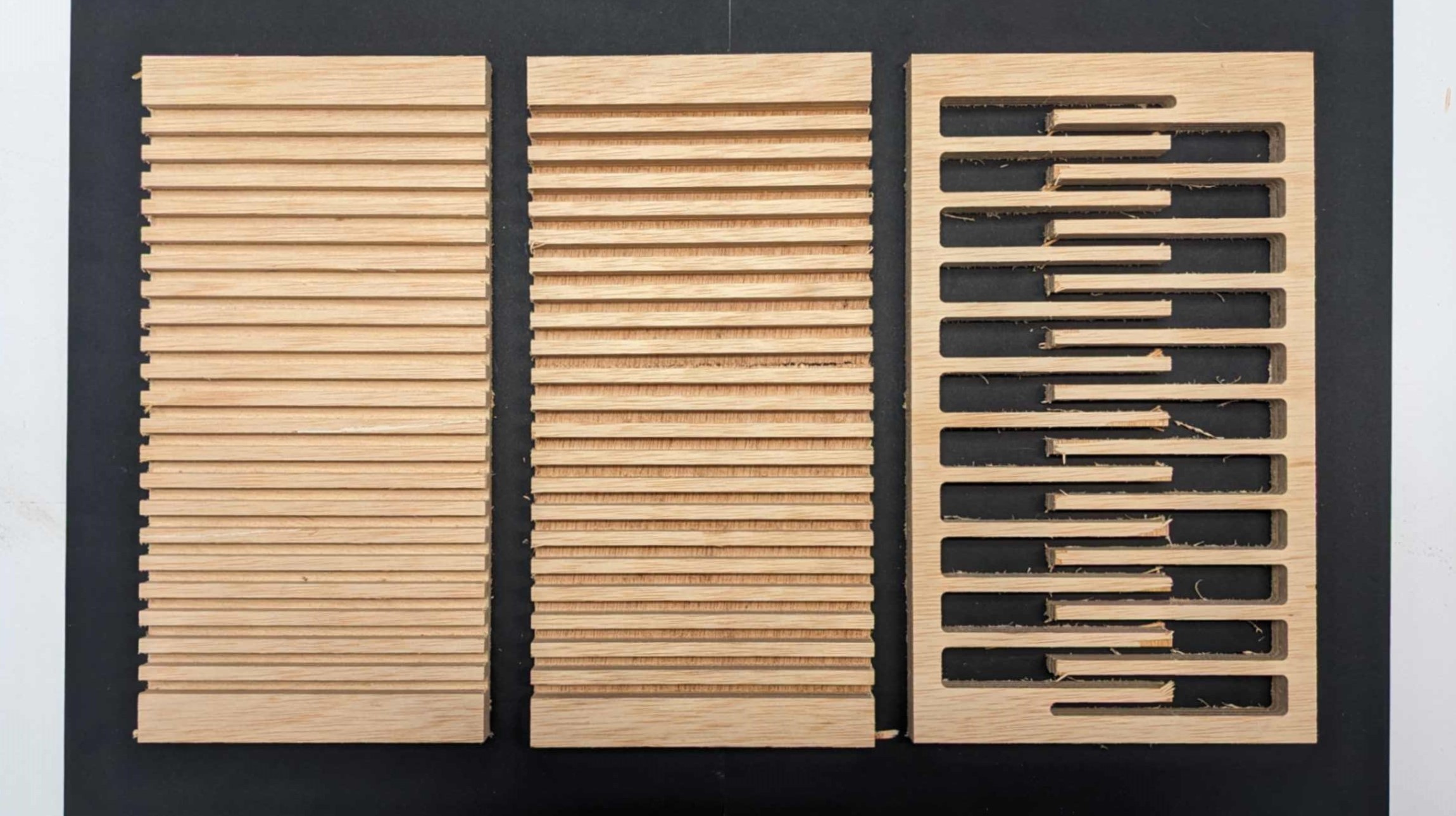
As a test, I made 3 versions of Living Hinge(connecting parts 6mm, 9mm, 12mm), 2 versions of Double Curvature (connecting parts 6mm, 9mm), and a small piece for a snap joint.
Files01_CNC_flex_test1.3dm
/jpeg-optimizer_01_EamesChair_03.JPG)
RhinoCAM
Next, I move to RhinoCAM which is a plugin for Rhino to generate Gcode. Gcode is a list of coordinates which tells the machine to move the XYZ axis. In RhinoCAM, I adjust a setup for the machine.
This software allowed me to generate toolpath, feedrate, spindle speed, and etc.
The workflow starts from setting up Stock which is a material that I want to mill, and also setting up the drill for milling. Next, I set locating for screws by coordinating points around the cutting area. Then I set settings for each type of milling such as Profiling, Pocketting, or Engraving. After adjusting all the settings, I generate Gcode in two different files. One is for only drilling those holes, and another is for milling the rest.
These screenshots show more detailed settings for each parameter which my tutor helped me to set up. This can be used as a reference for future milling.
Files00-Screws-6mmFlat_CNC_flex_test_Standard Drill.nc
01-Cuts-6mmFlat_CNC_flex_test_Standard Drill.nc
/jpeg-optimizer_00_DRILL.JPG)
Setting custom endmill
/jpeg-optimizer_00_MATERIAL.JPG)
setting material dimensions
/jpeg-optimizer_00_screw_01.JPG)
Placing hole for screws
/jpeg-optimizer_00_screw_02.JPG)
Choosing endmill for screw holes
/jpeg-optimizer_00_screw_03.JPG)
Splidle Speed 18000 RPM
/jpeg-optimizer_00_screw_04.JPG)
Stock MaxZ + Dist 30
/jpeg-optimizer_00_screw_05.JPG)
Drill Type: Standard Drill
/jpeg-optimizer_00_screw_06.JPG)
Minimum Distance Sort
/jpeg-optimizer_01_joint_pocket_00.JPG)
Generating toolpath created
/jpeg-optimizer_01_joint_pocket_01.JPG)
Hit generate button
/jpeg-optimizer_01_joint_pocket_02.JPG)
Flat_DC_6mm is auto selected
/jpeg-optimizer_01_joint_pocket_03.JPG)
Splidle Speed 18000 RPM
/jpeg-optimizer_01_joint_pocket_05.JPG)
Tolerance:0.01, Cut Direction Climb
/jpeg-optimizer_01_joint_pocket_06.JPG)
Total cut Depth: 15.4
/jpeg-optimizer_01_joint_pocket_07.JPG)
Approach Motion Length: 0.6S
/jpeg-optimizer_01_joint_pocket_08.JPG)
No modification for Advanced Cut Parameters
/jpeg-optimizer_01_joint_pocket_09.JPG)
Minumum Distance Sort
/jpeg-optimizer_02_ENGRAVING_00.JPG)
Generting toolpath
/jpeg-optimizer_02_ENGRAVING_01.JPG) Select Geometry and hit generate button
Select Geometry and hit generate button
/jpeg-optimizer_02_ENGRAVING_02.JPG)
Choose end mill Flat_DC_6mm
/jpeg-optimizer_02_ENGRAVING_03.JPG)
Spindle Speed 18000 RPM
/jpeg-optimizer_02_ENGRAVING_04.JPG)
Stock MaxZ + 10
/jpeg-optimizer_02_ENGRAVING_05.JPG)
Tolerance 0.03, Total Cut Depth 15.4
/jpeg-optimizer_02_ENGRAVING_06.JPG) Entry/Exit: Along path Angle 10
Entry/Exit: Along path Angle 10
/jpeg-optimizer_02_ENGRAVING_07.JPG)
Minimum Distance Sort
/jpeg-optimizer_03_OUTLINE_00.JPG)
generating toolpath
/jpeg-optimizer_03_OUTLINE_01.JPG)
select the geometry and hit generate button
/jpeg-optimizer_03_OUTLINE_02.JPG)
Select Endmill Flat_DC_6mm
/jpeg-optimizer_03_OUTLINE_03.JPG)
Spindle Speed 18000 RPM
/jpeg-optimizer_03_OUTLINE_04.JPG)
Stock MaxZ + 10
/jpeg-optimizer_03_OUTLINE_05.JPG)
Tolerance 0.03, Cut Direction Climb
/jpeg-optimizer_03_OUTLINE_06.JPG)
Total Cut depth: 15.4
/jpeg-optimizer_03_OUTLINE_07.JPG)
Entry/Exit: Along path Angle 10
/jpeg-optimizer_03_OUTLINE_08.JPG)
Bridge: Rectangular, 4
/jpeg-optimizer_03_OUTLINE_09.JPG)
Minimum Distance Sort
CNC Milling
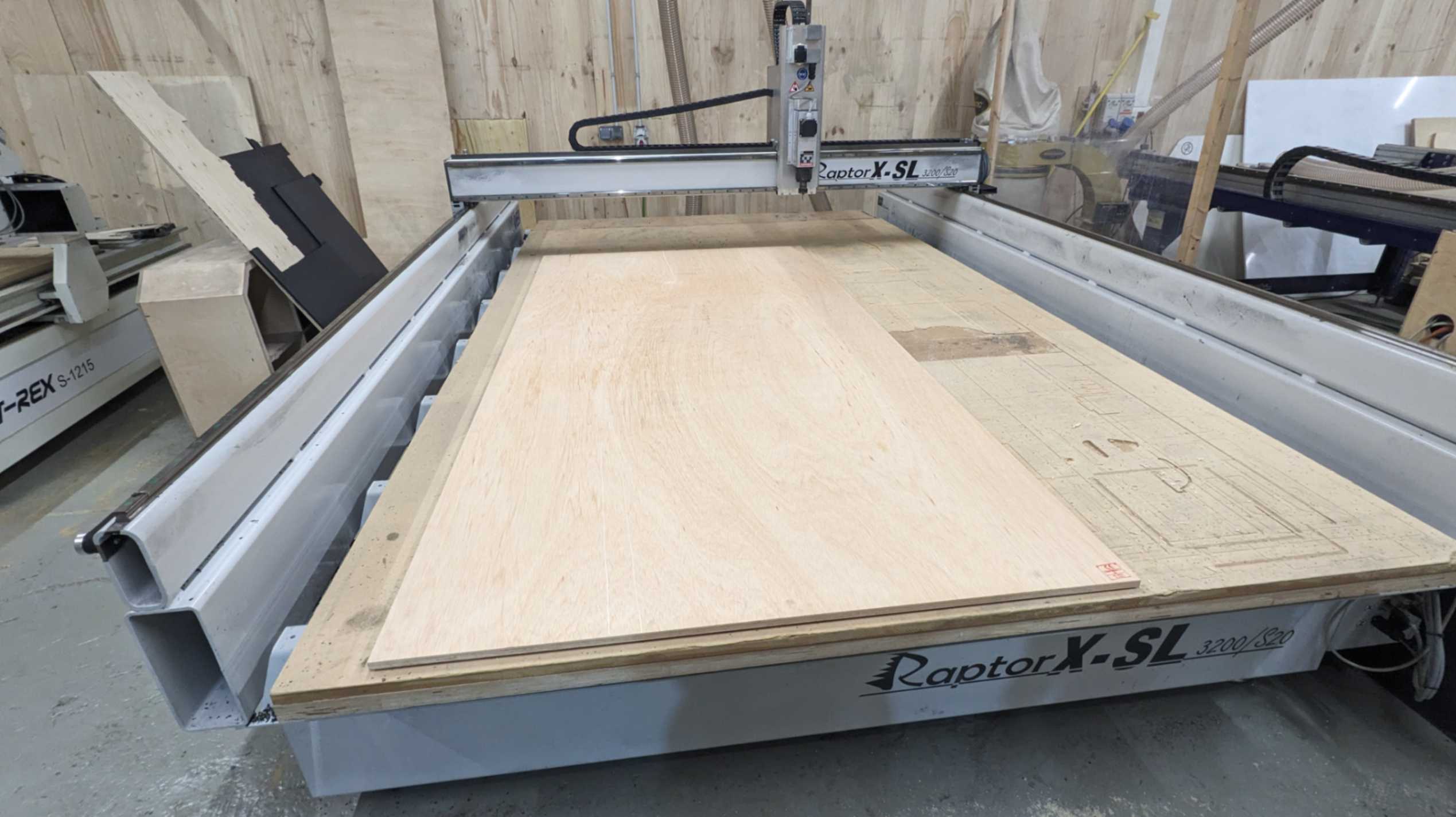
After getting the files ready, it was time to fabricate. I explain the workflow below step by step.
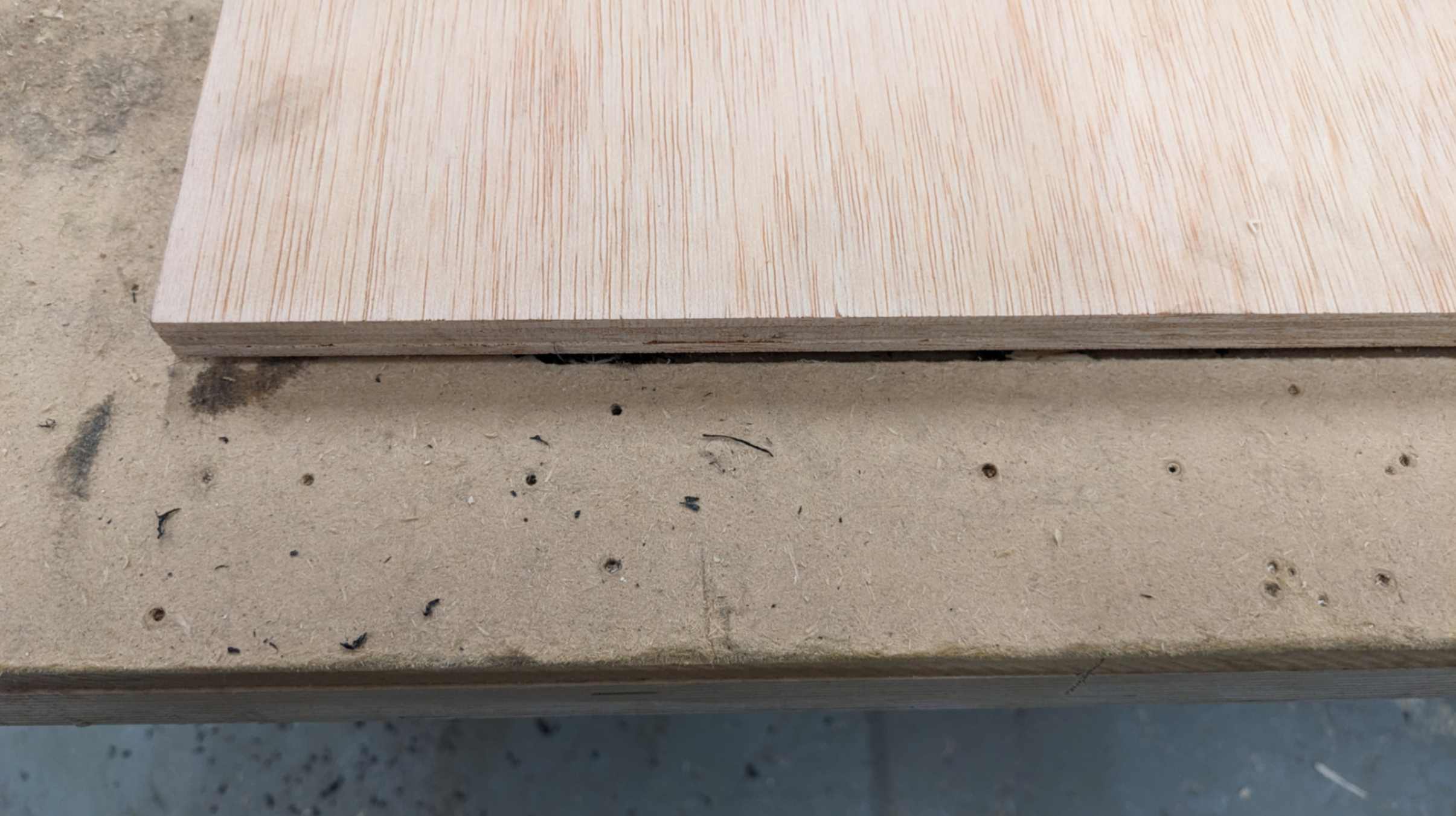
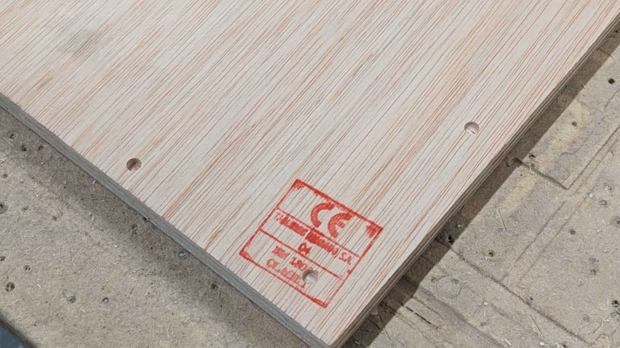
- Check material to see which side is bending
- Place the material with the bending side up
- Adjust the placement of material on the bed by aligning the existing straight line
- Untie the milling head by using two renchs
- Clean the head parts by air compressor
- Change the end mill (this time I changed to Down cut end mill)
- Set X and Y origin by moving the head from the PC and remote controller
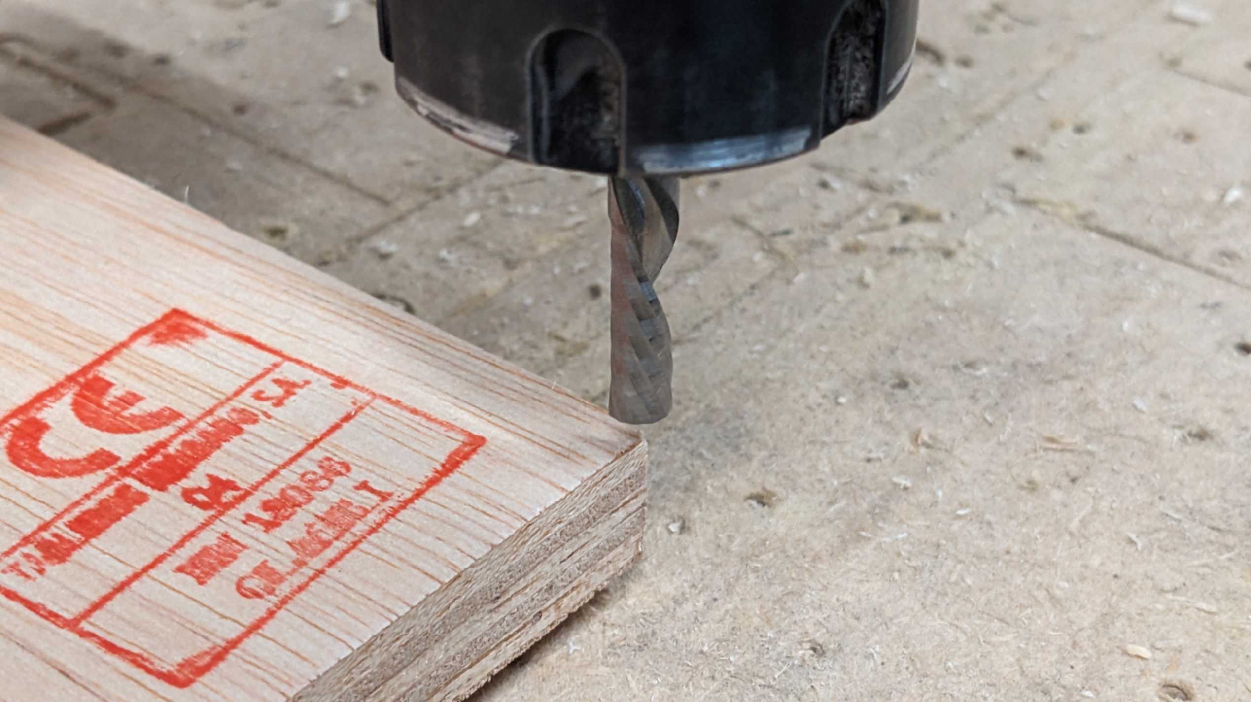
- Set Z origin by slowly bringing down the end mill to the surface of the material (manually spinning the end mill helps detect when it touches the surface)
- Run the drill hole file to locate the placement for screws
- Put screws to the holes to secure the material to the bed
- Re-do the Z origin in the same way
- Run the main milling file.
- During the milling, It is possible to pause. When continuing after the pause, it is good to go back a few steps and spin the drill in advance.
- Stay by the side of the machine and not in front
- Wear safety glasses and headphones. Also, wear a mask if it is dusty.
- When the milling job is done, use chisel and hammer to break bridges
- Take out milled pieces
- unscrew the material
- Clean all the dust with vacuum cleaner
Check the bending
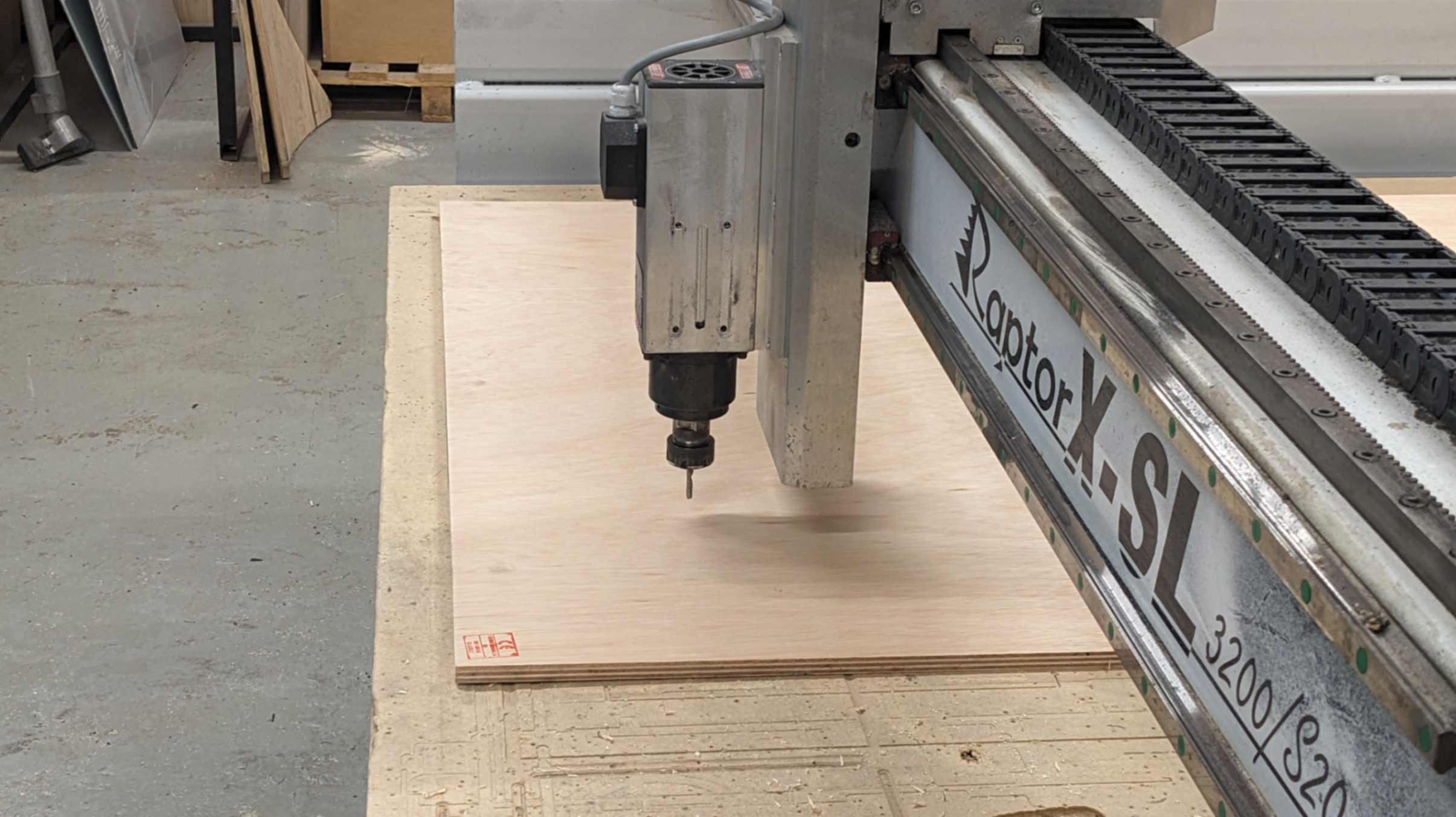
Place the material on the bed
Make sure it is straight
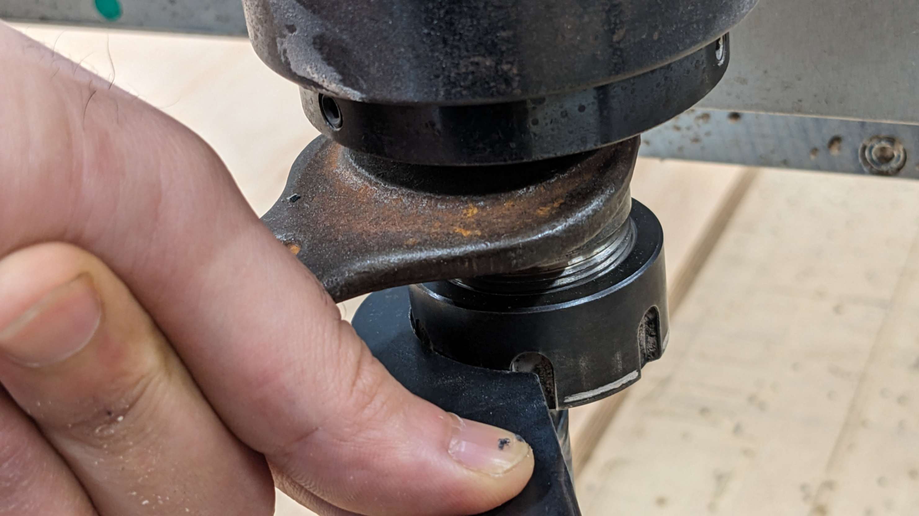
Untighten the spindle
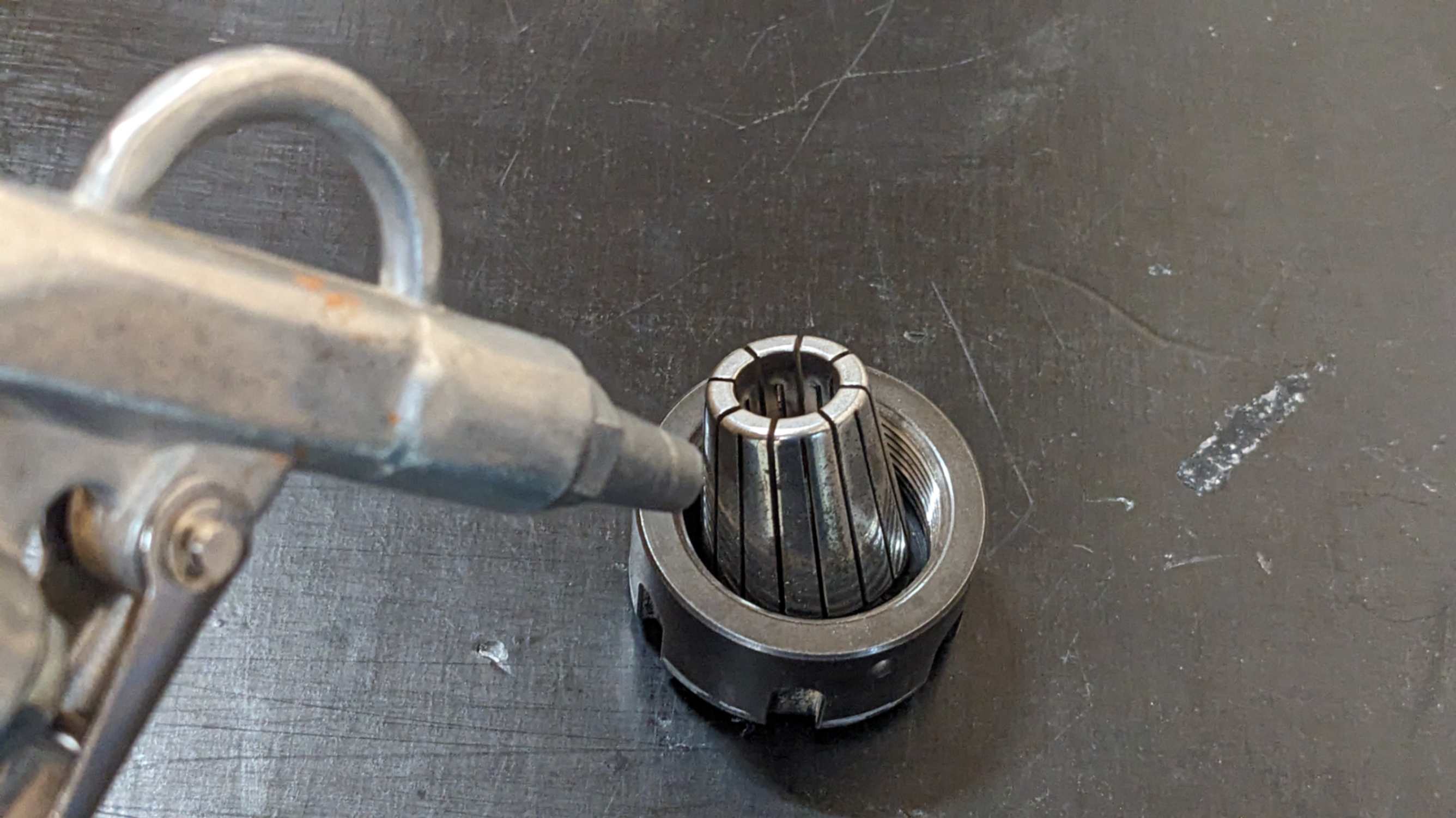
Clean the holder
Open the pc connected to the CNC
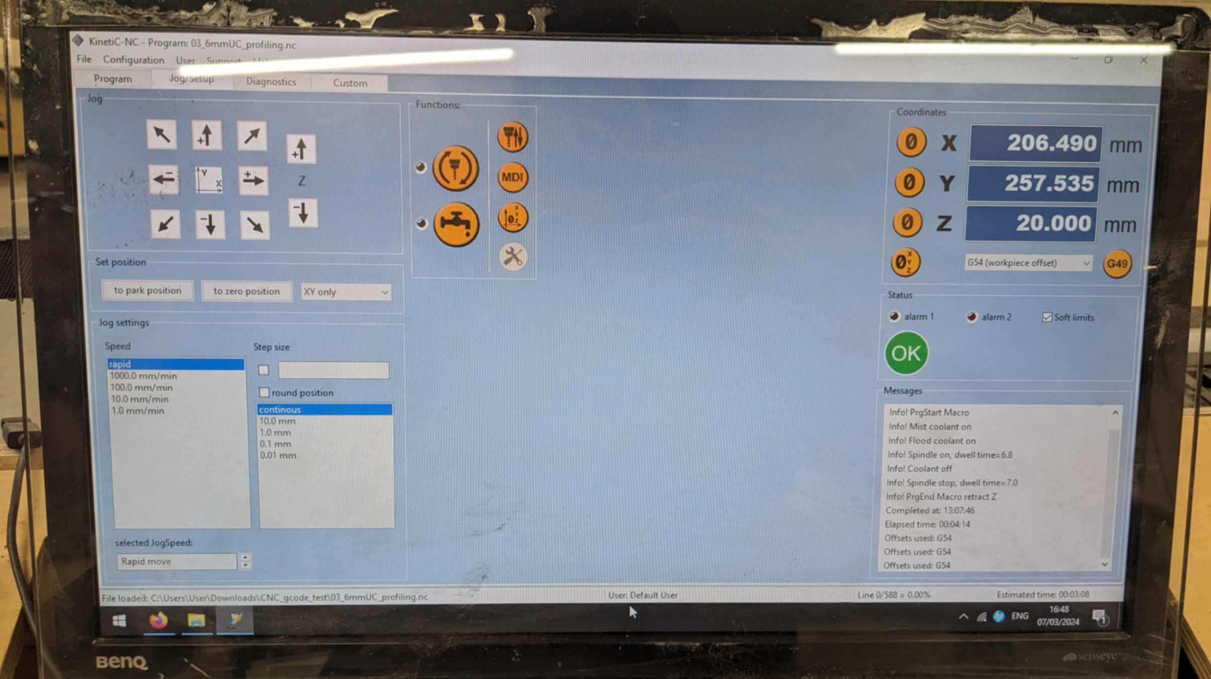
Set X,Y,Z origin
Open the screws gcode and run it
stay away from the machine while its running
holes for screws are milled
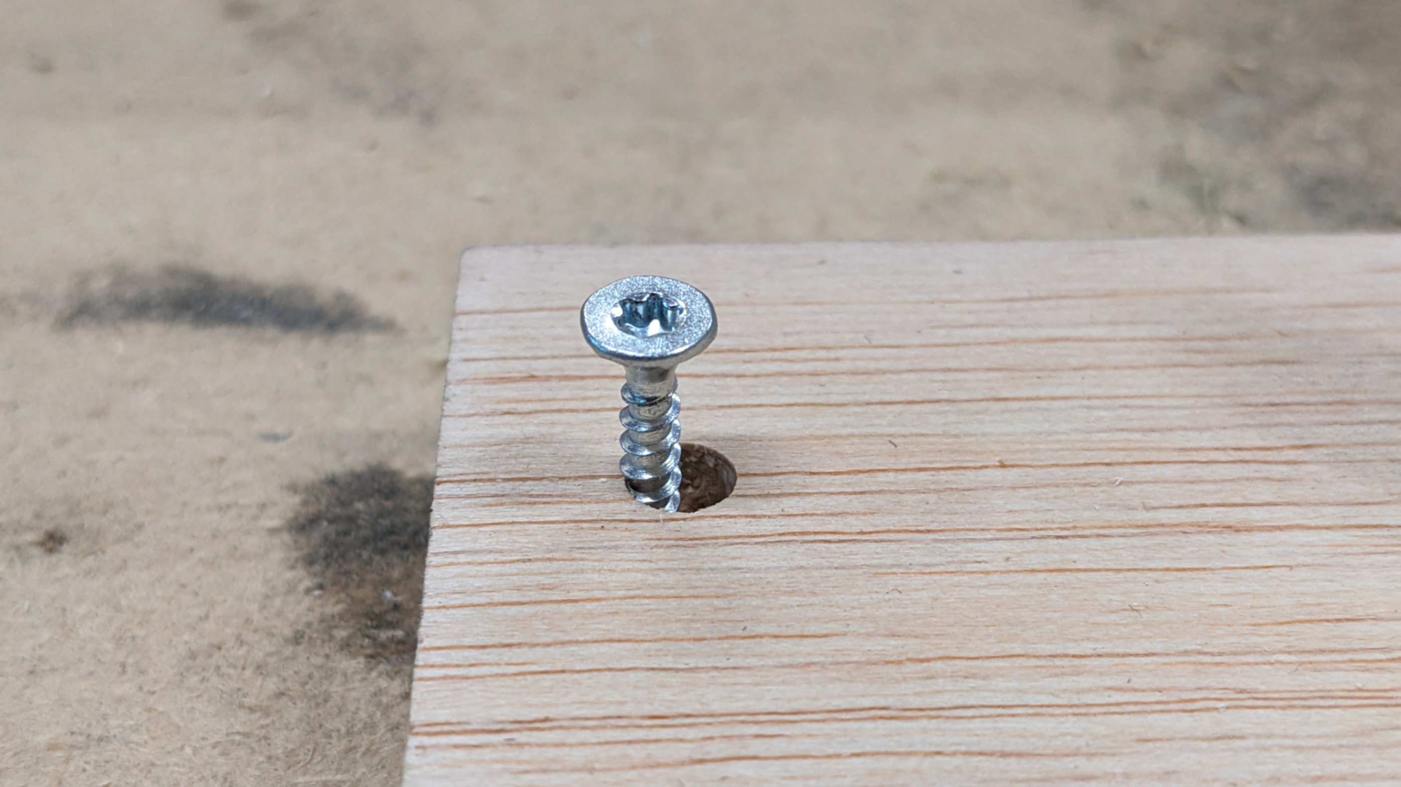
Screw down the material
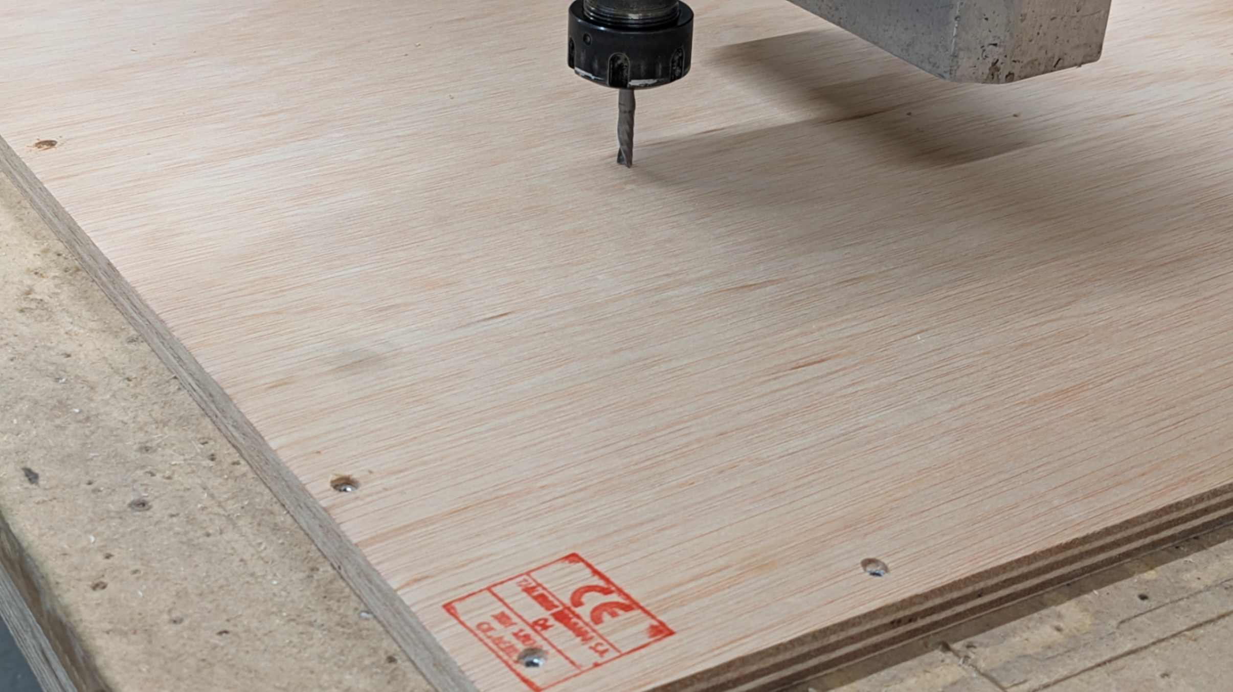
Re-set the Z origin
Open the test gcode and run it
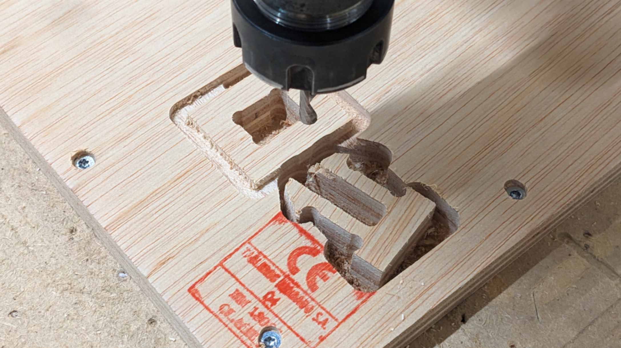
a piece moved while milling
Milled test piece
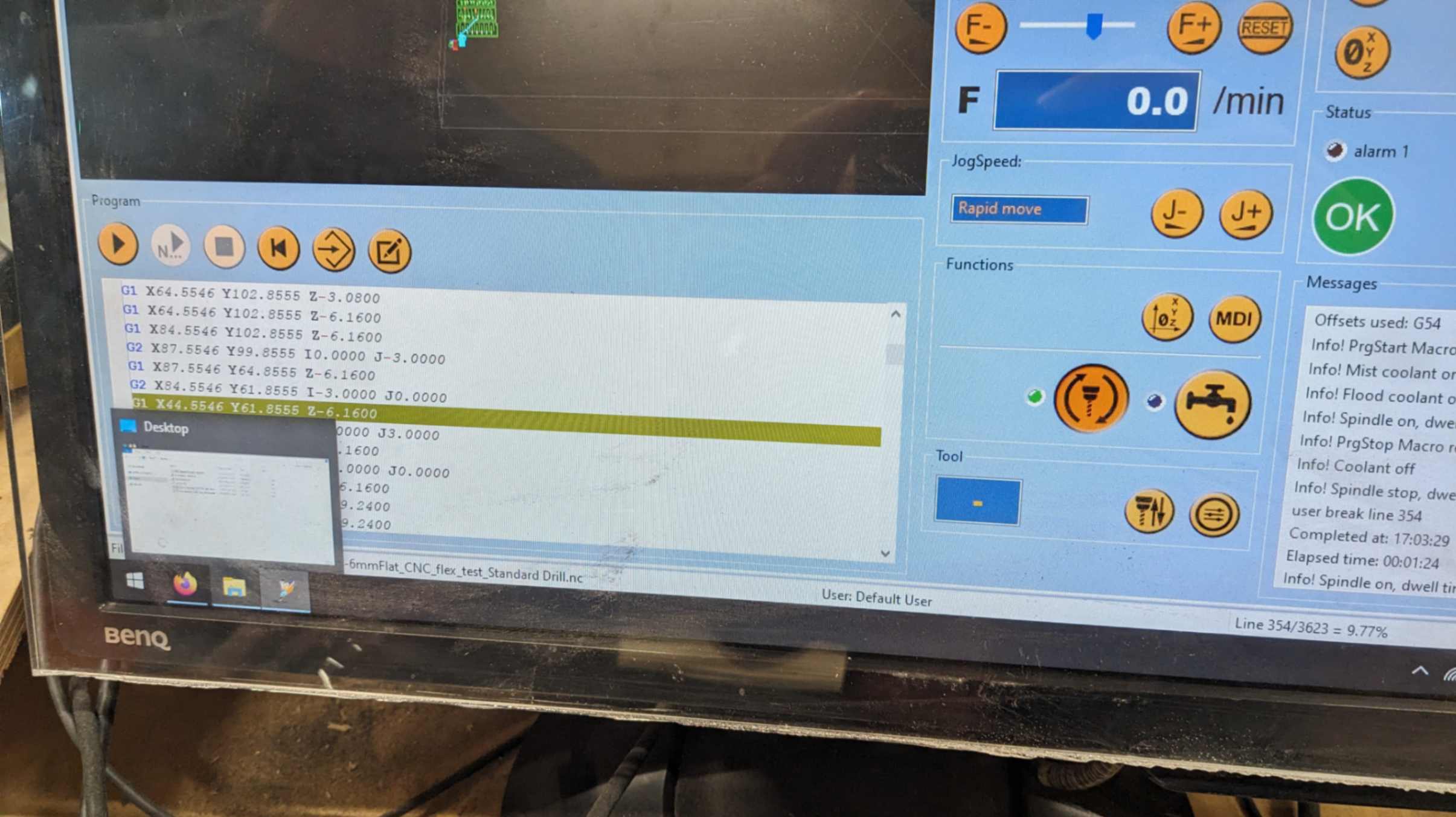
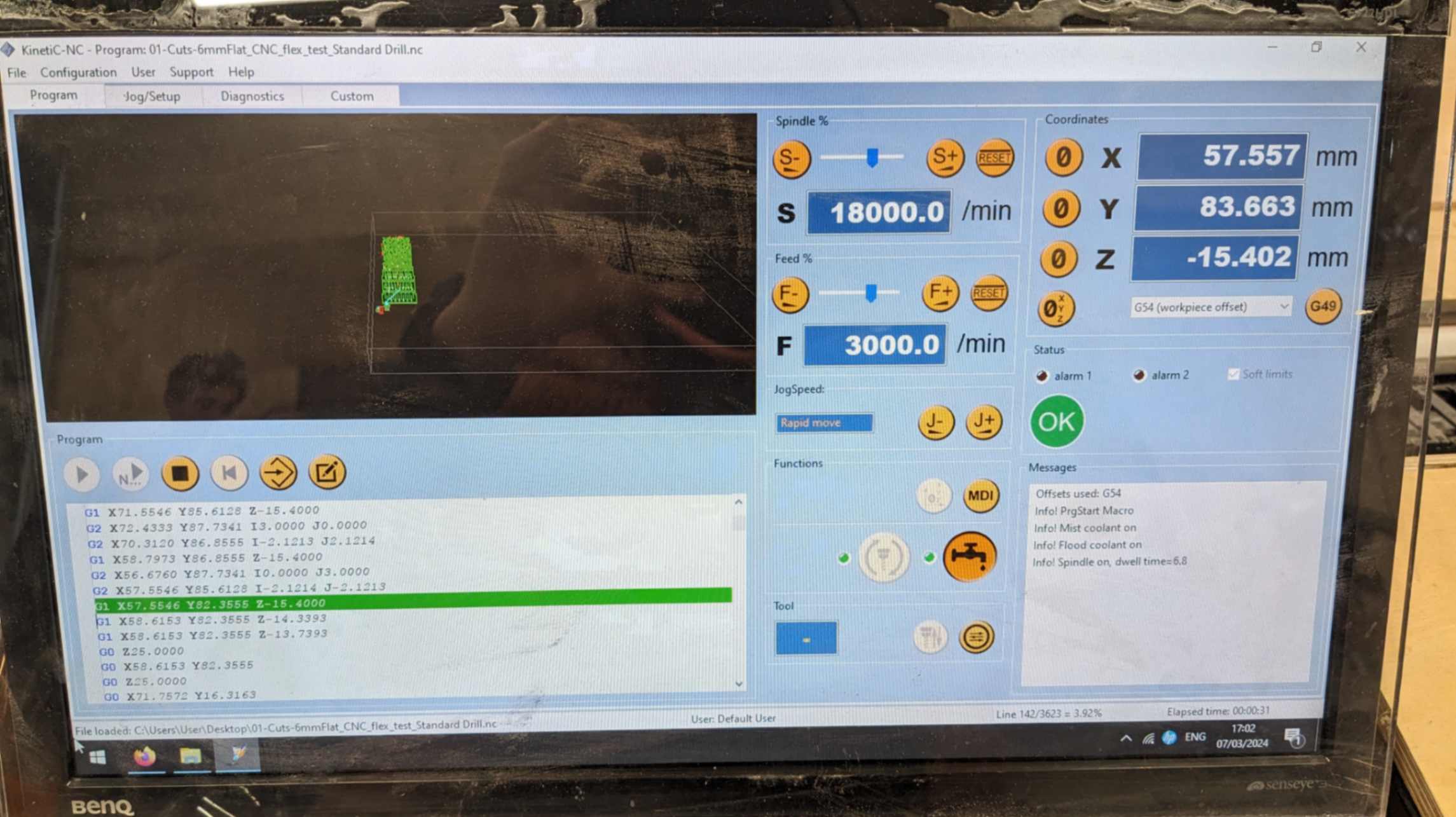
Pause the machine
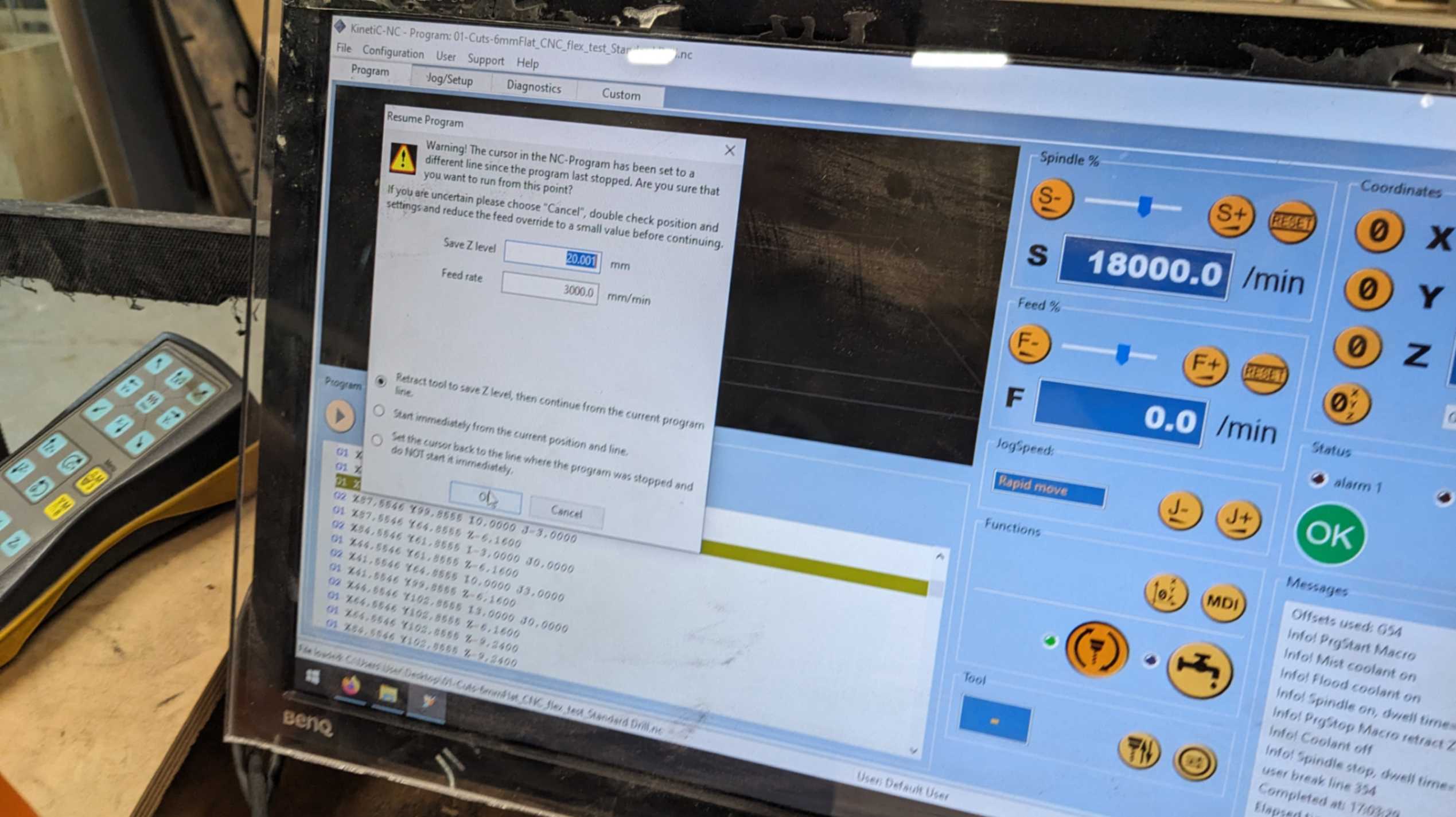
resume from the line before the stopped line
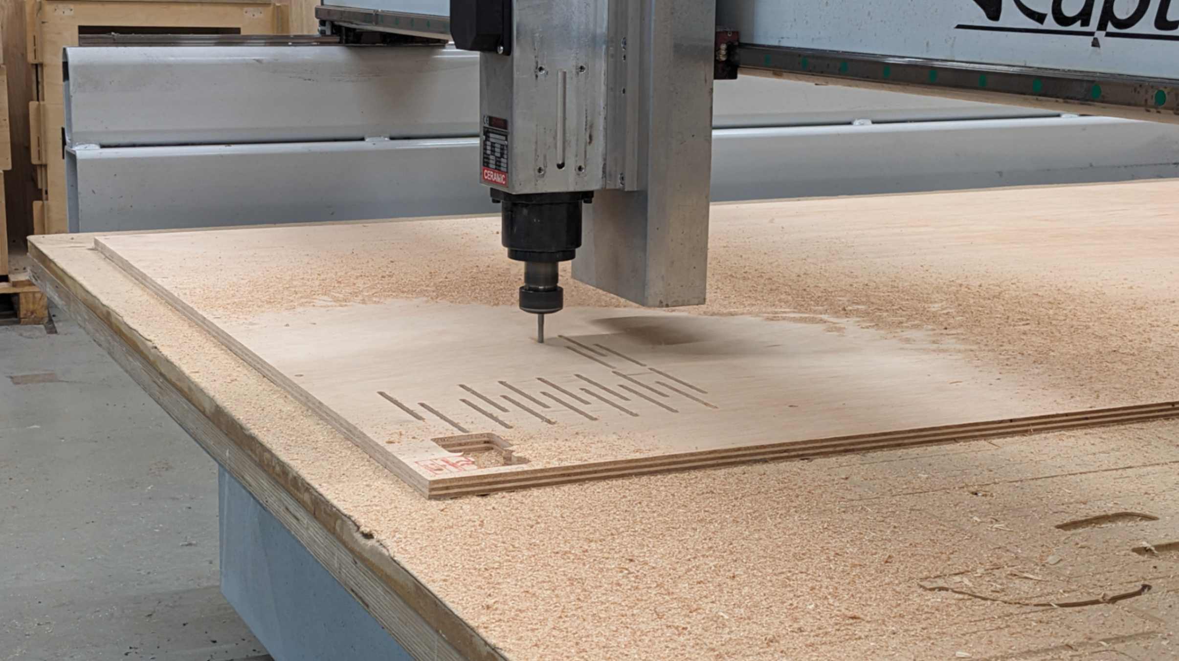
Millinf is done
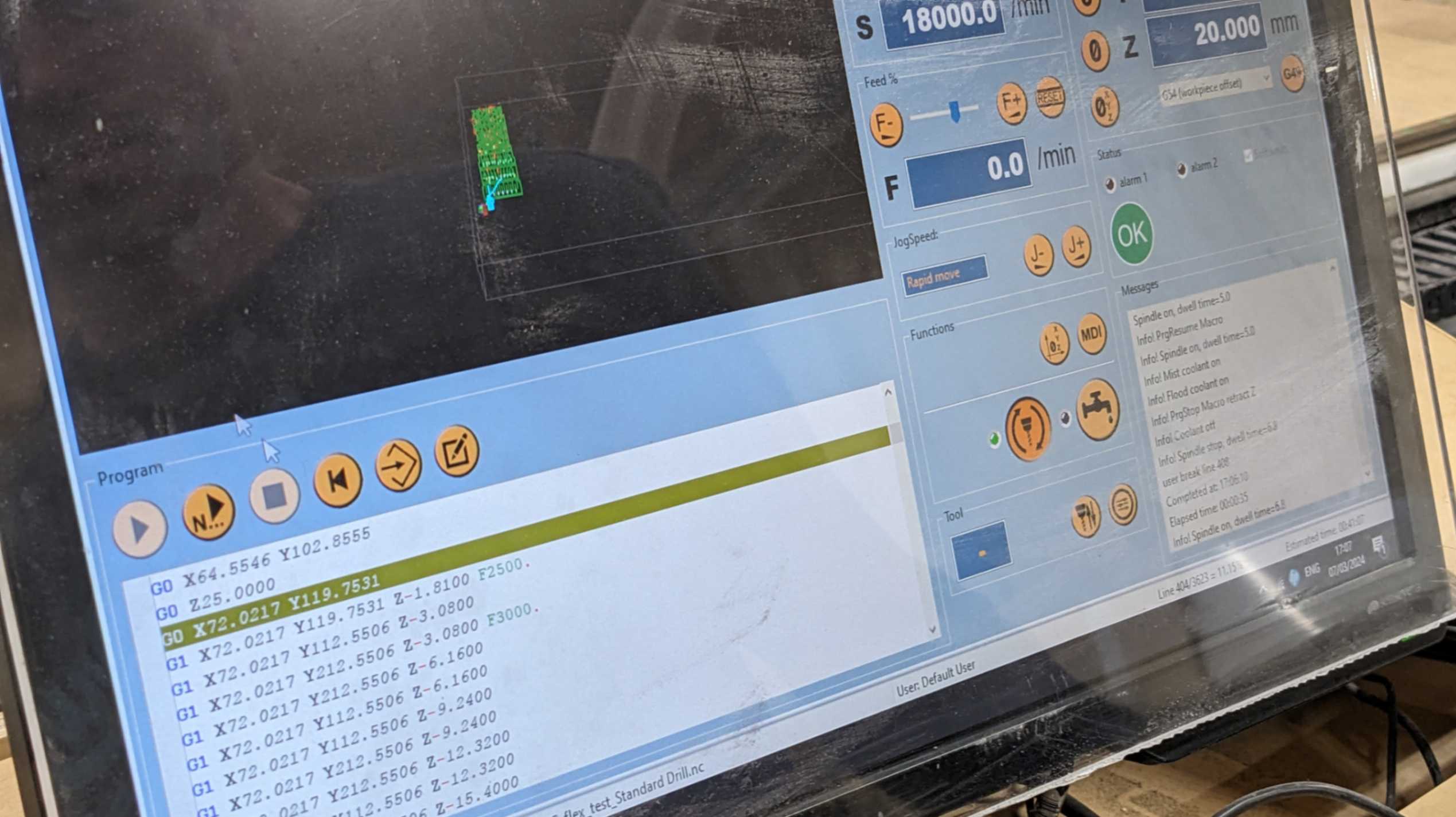
set of gcode lines
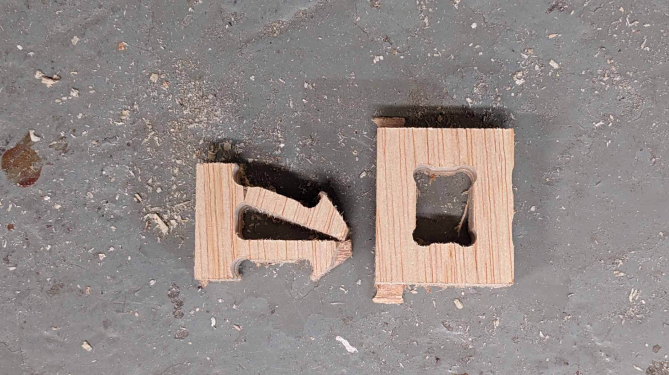
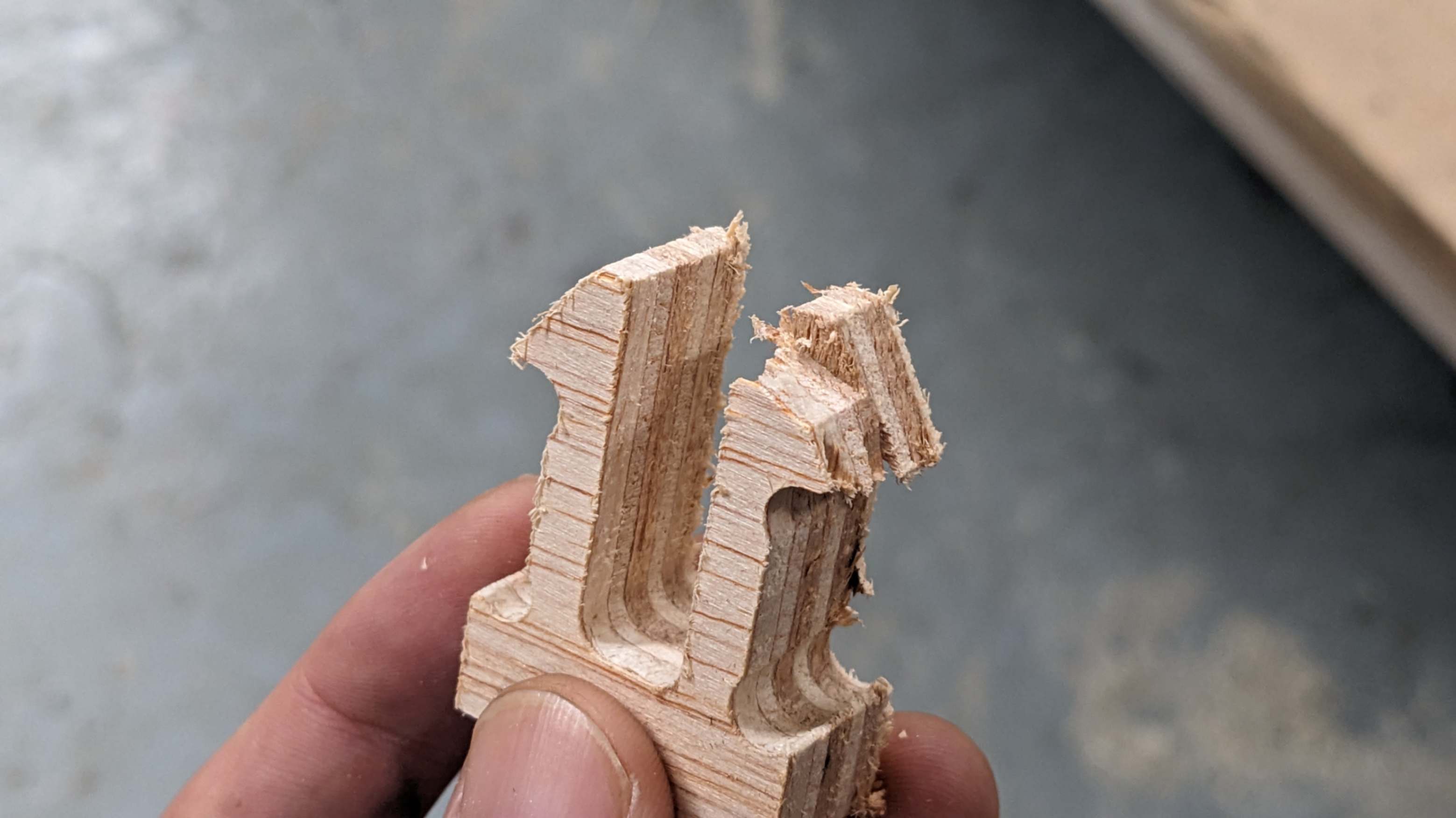
Falied test pieces
another test Pieces
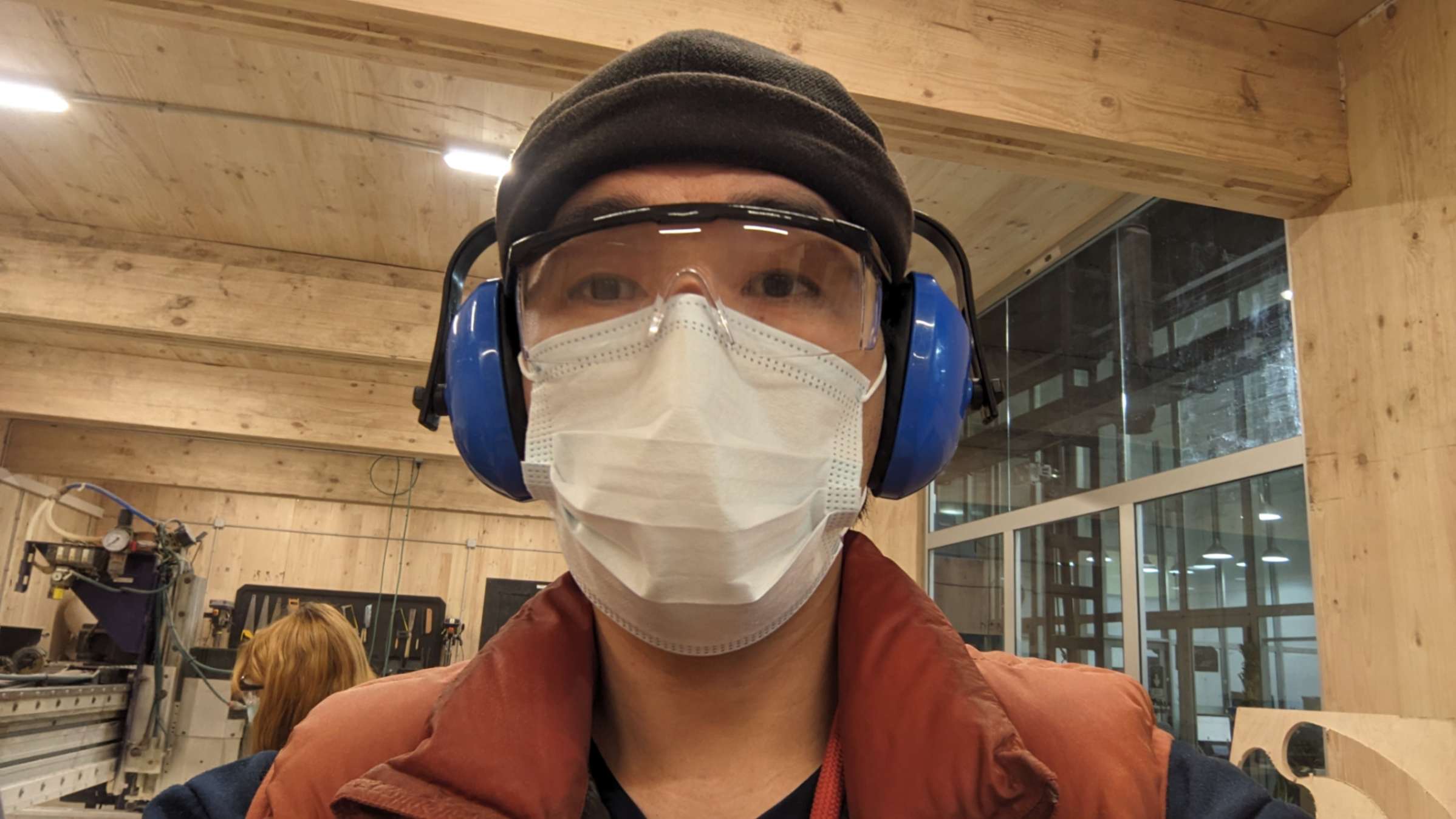
wearing safety gears
Milling is done
placement was too close
not enough offset
cleaning after
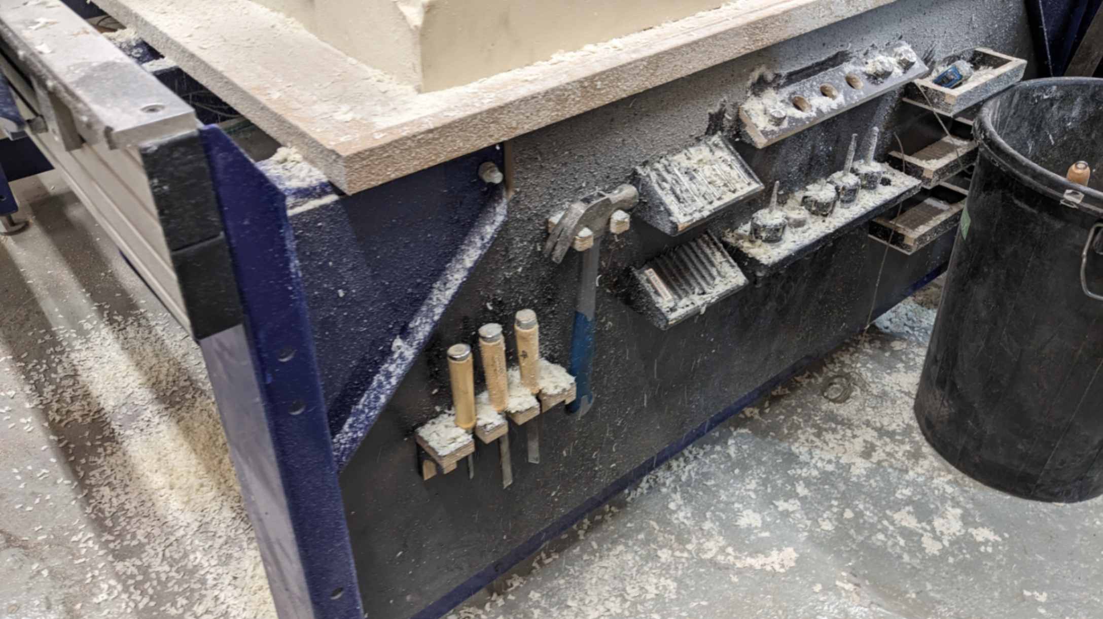
bring back tools
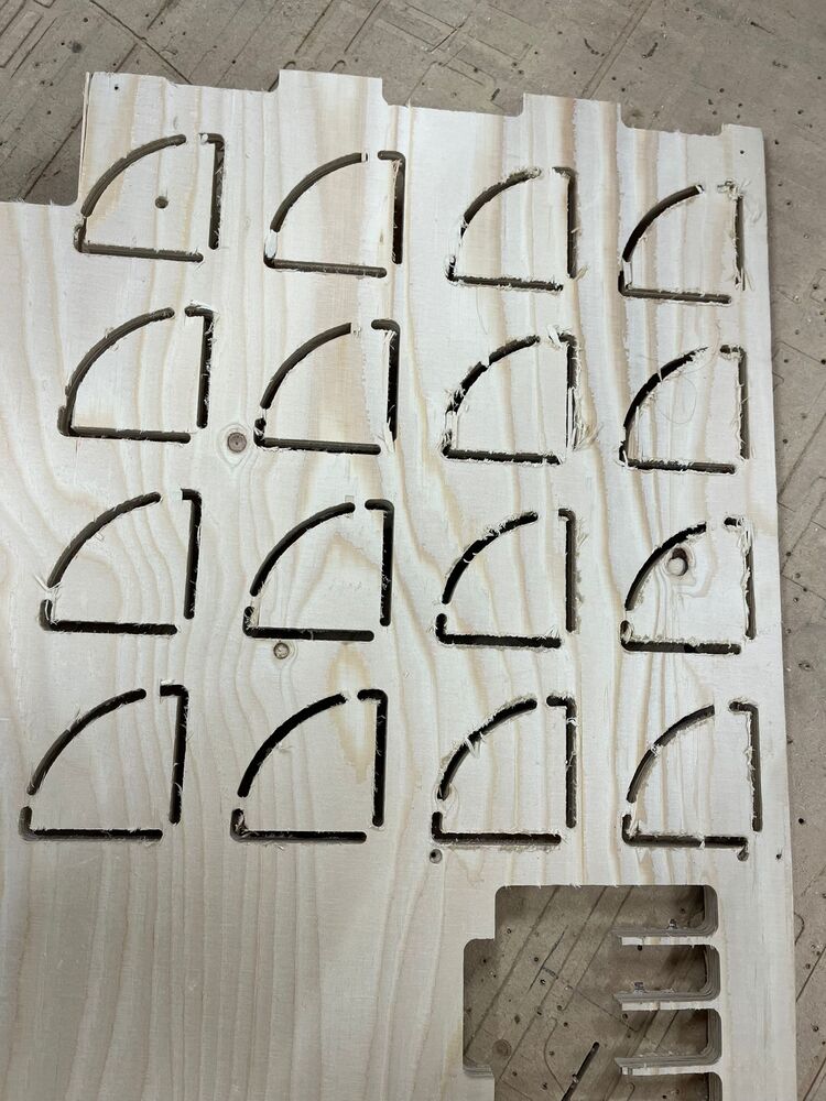
Test 1 Result
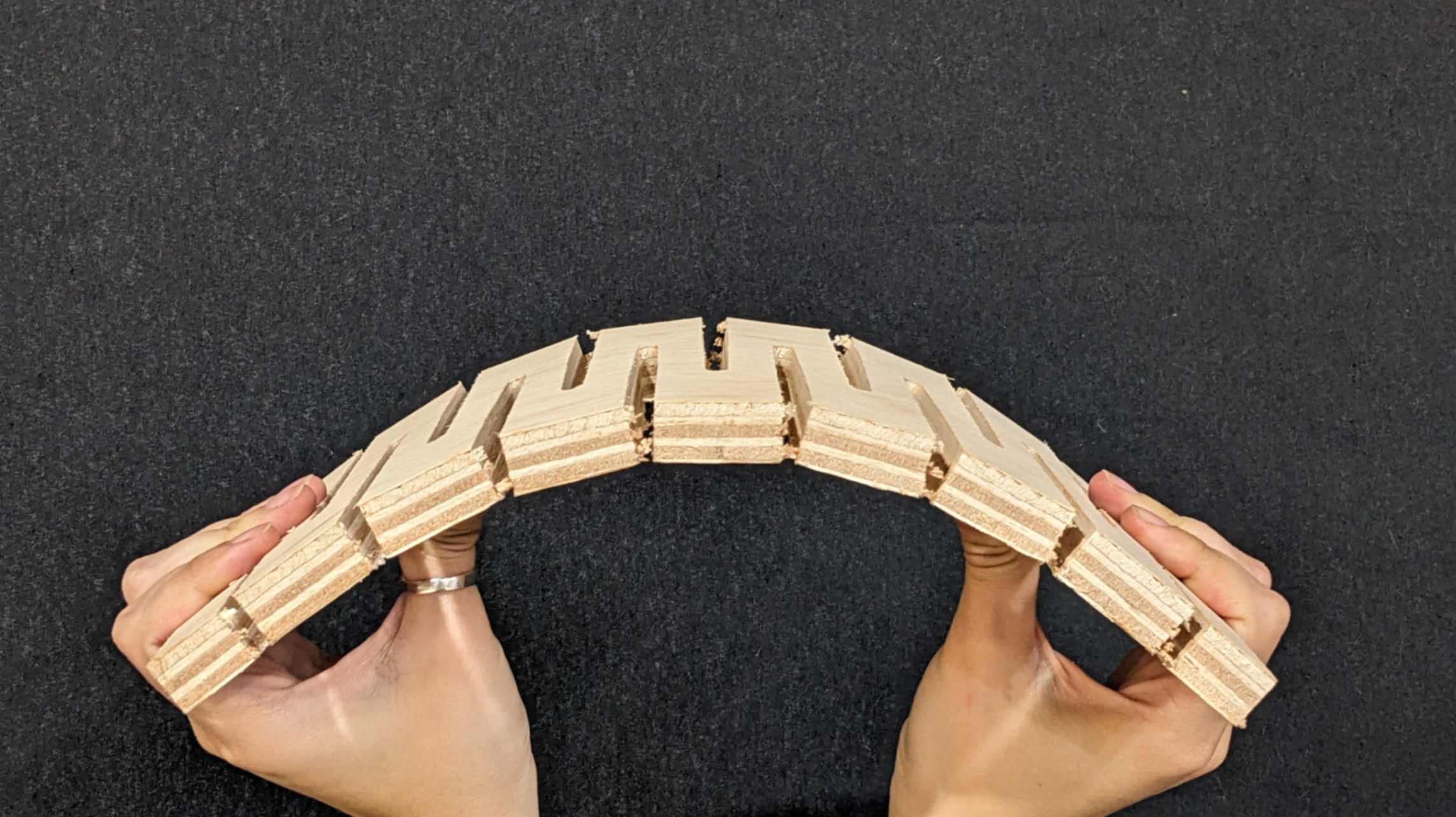
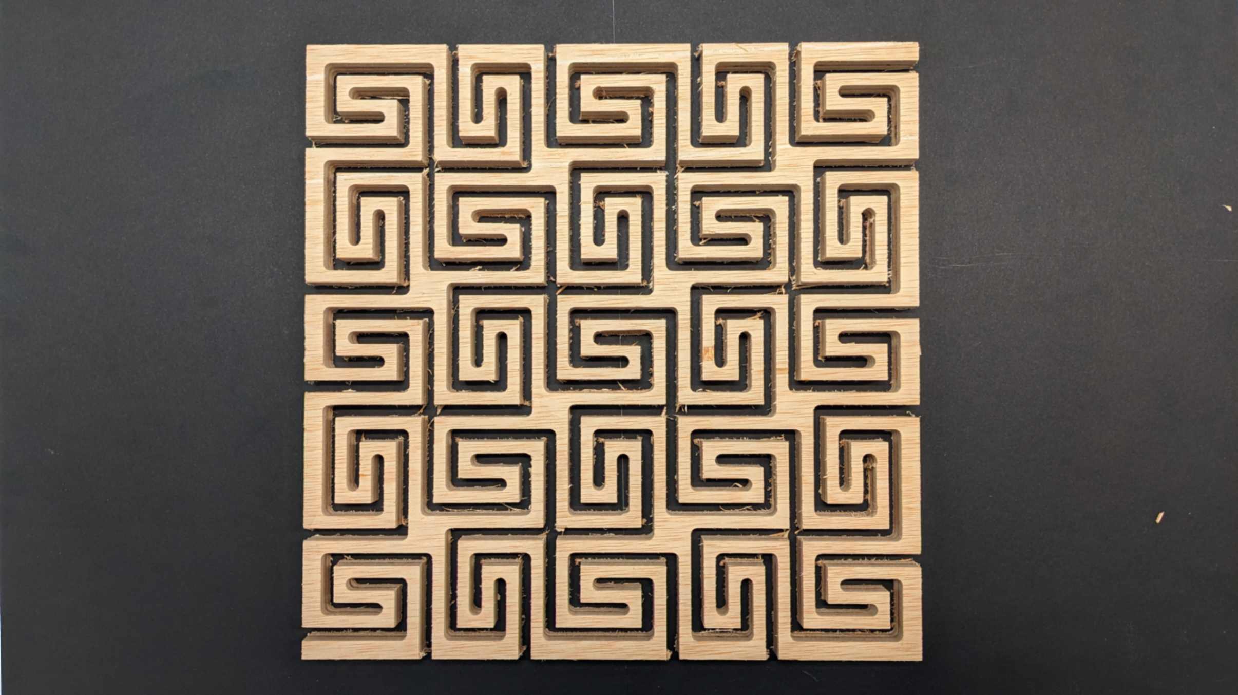
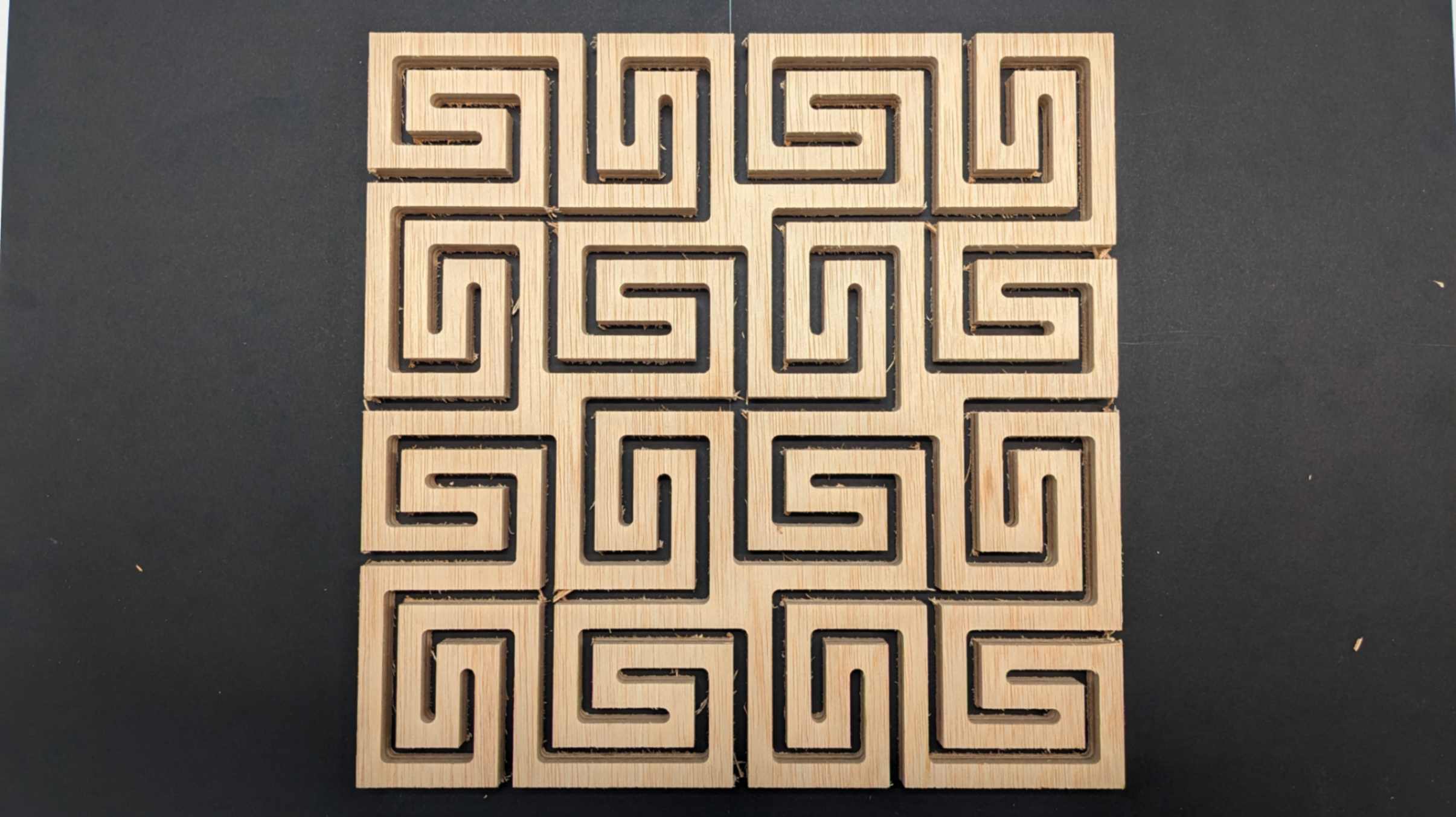
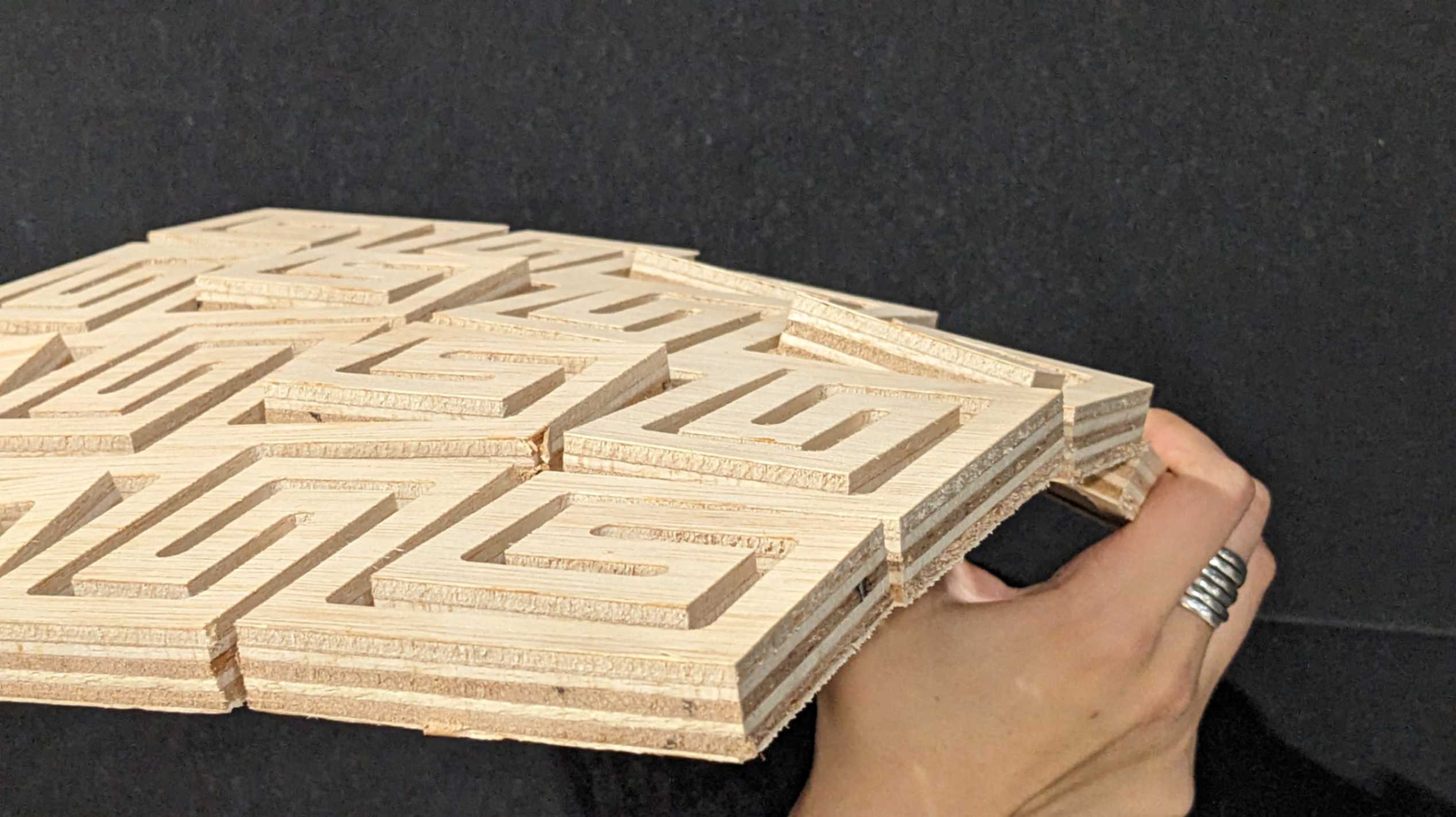
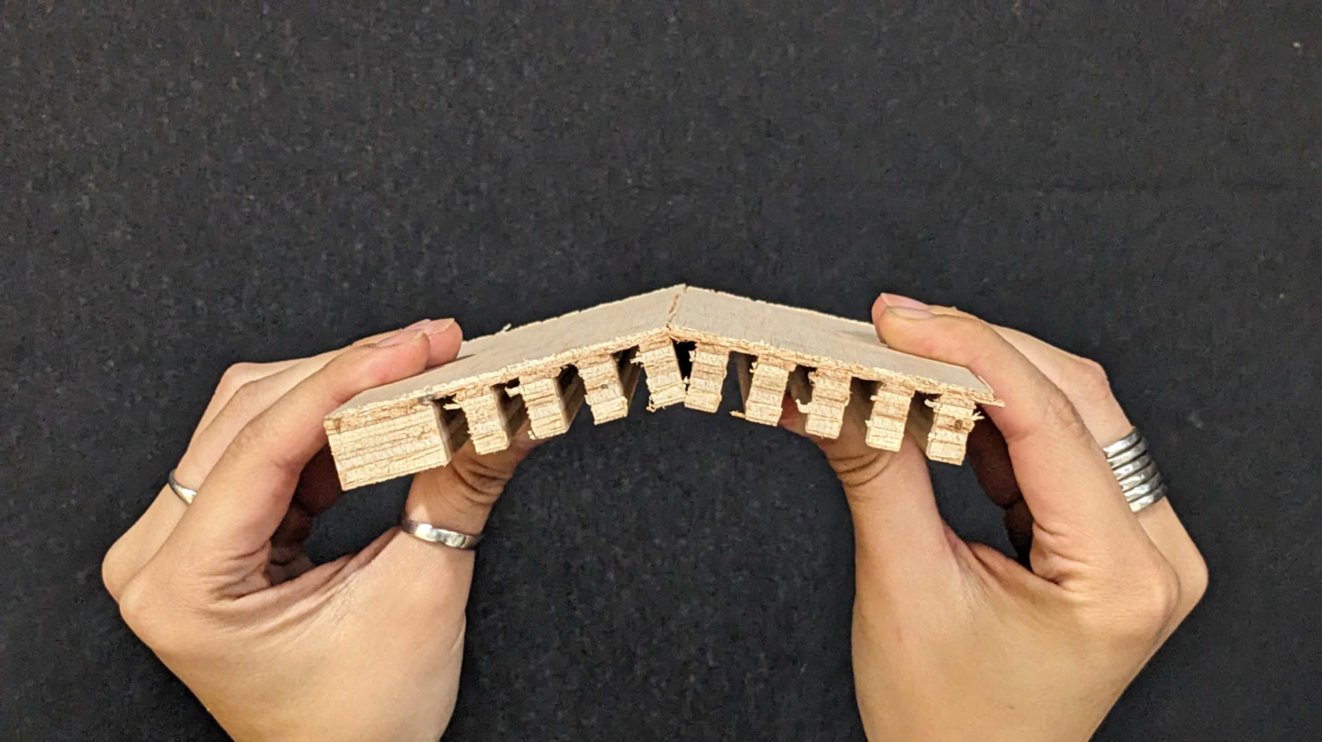
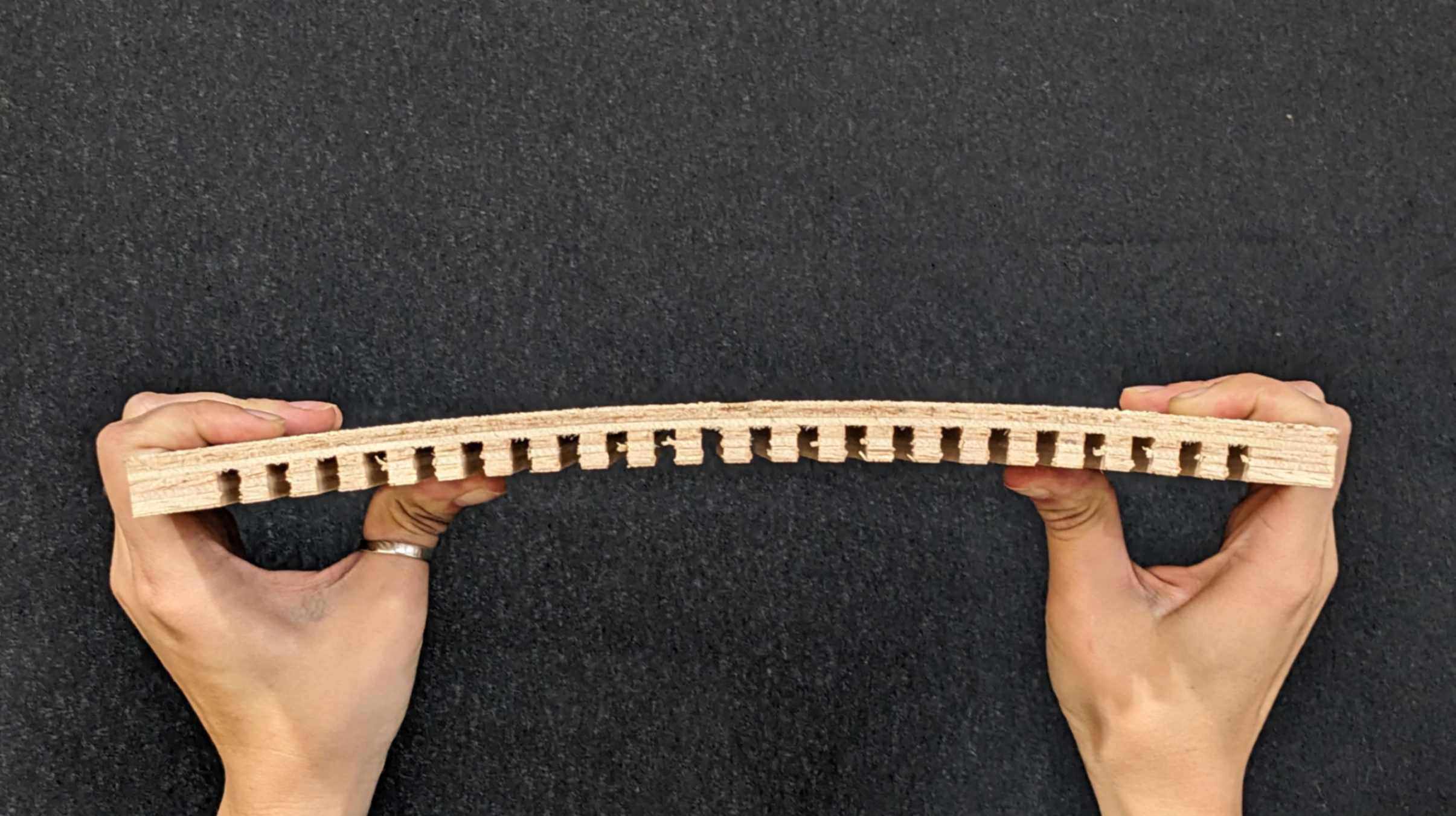
As a result, Living hinges were very different. The difference in thickness of the connecting parts was shown in the result of how much it bends. A living hinge with a 6mm connection was the closest to what I wanted to achieve. However the bending effect will also depend on the length of the piece, so it is also nice to test it with different lengths for a future investigation.
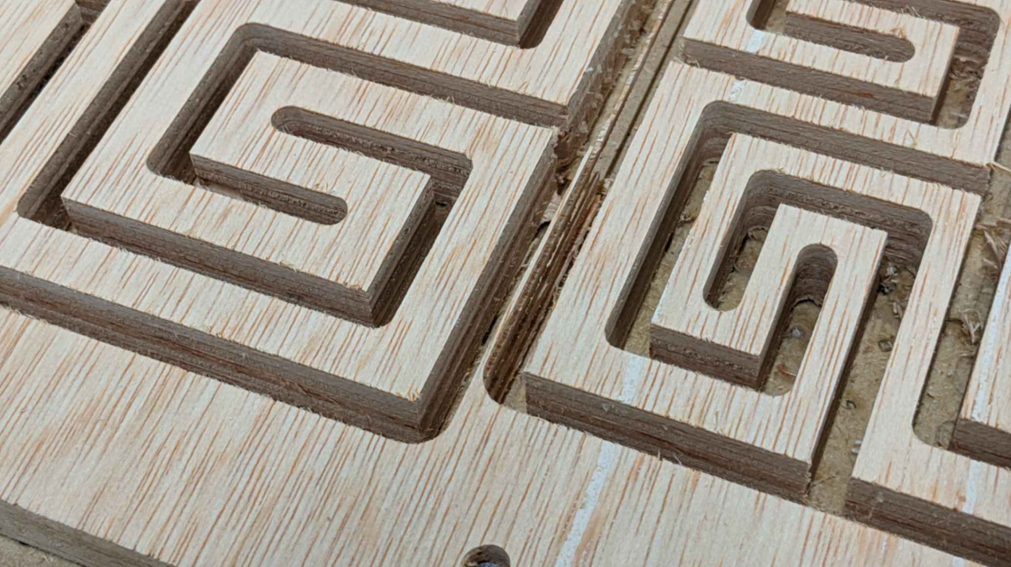
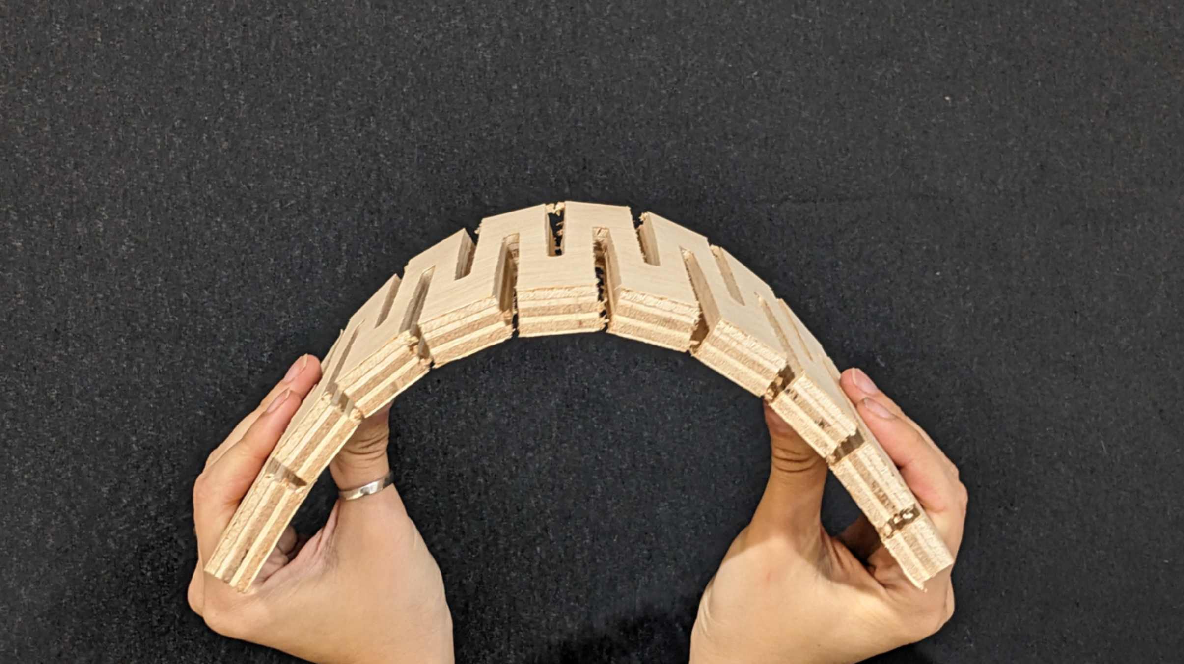
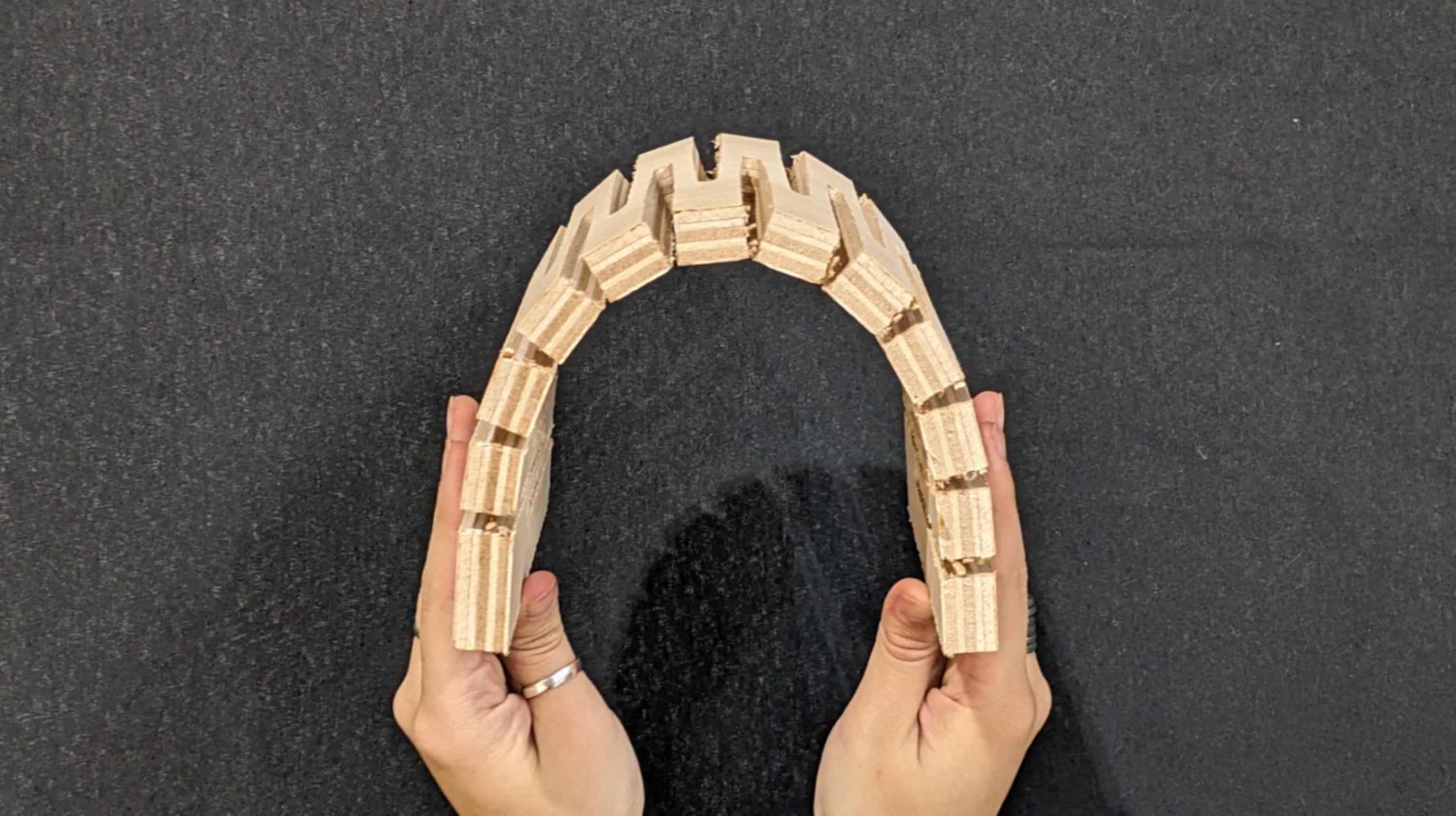
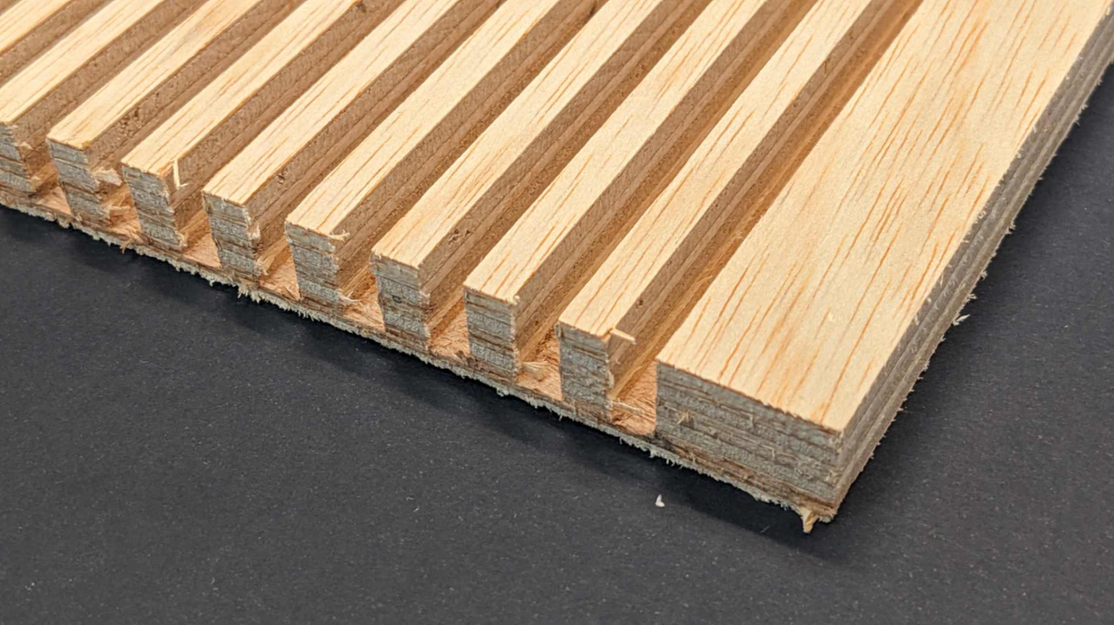
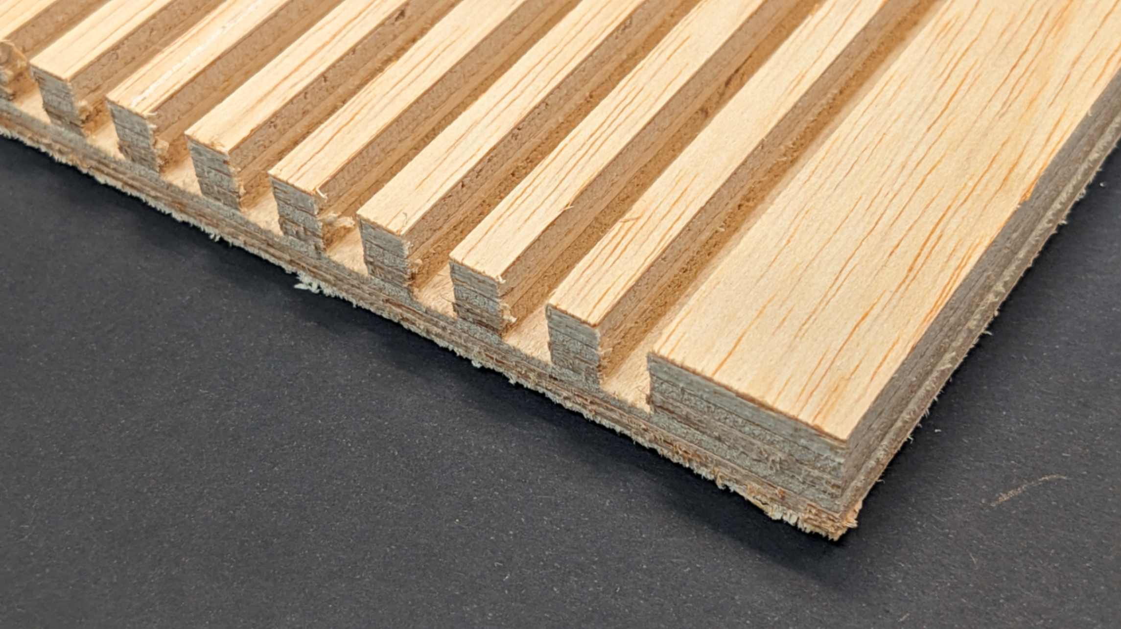
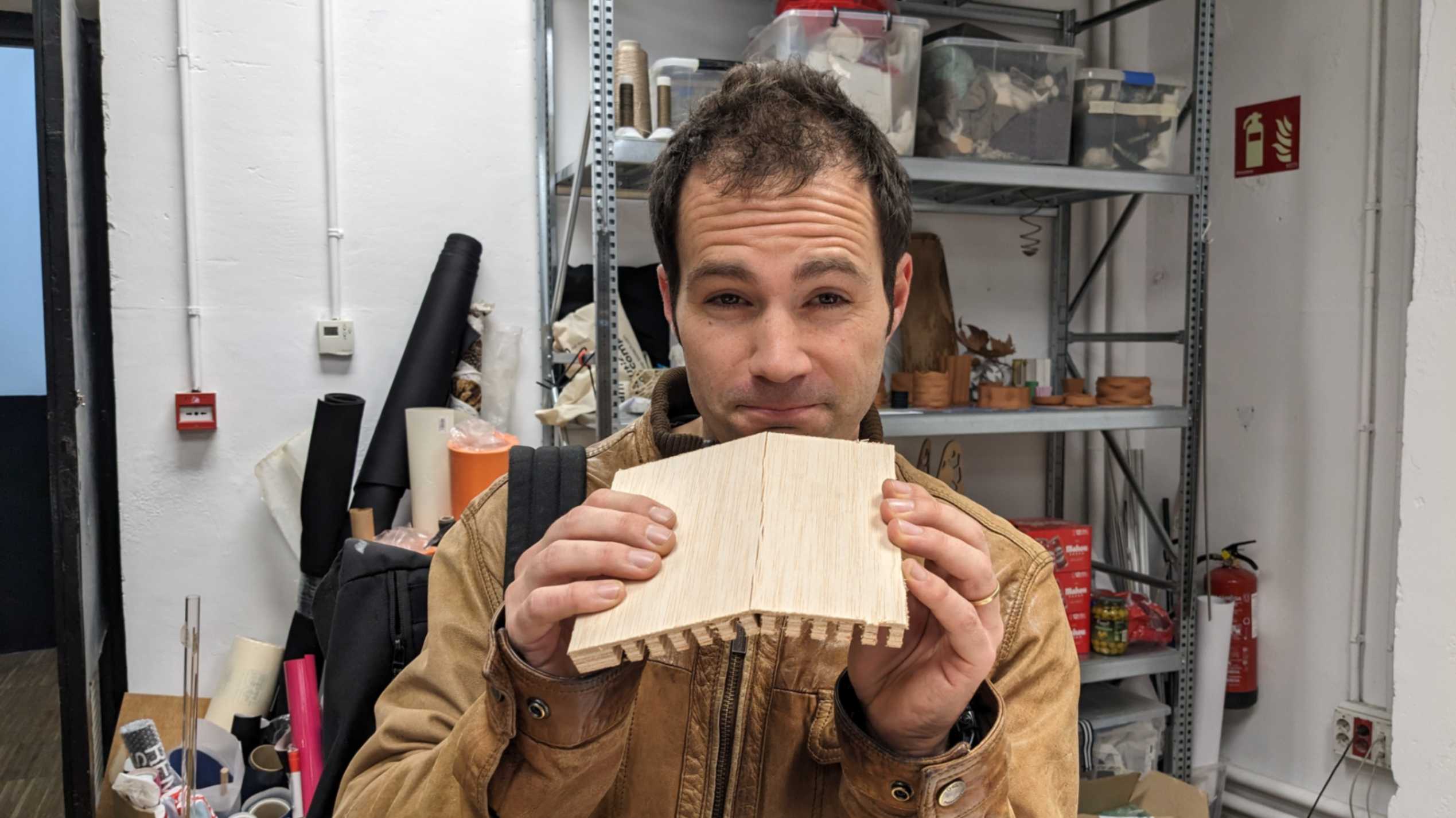
Double curvature was milled very nicely and I liked the look of them. The bending effect was not as strong as the laser cut version, since there is a limitation for how much the pattern can get complex. Although both of them were still bendable. I liked the 6mm version because it was more bendy than the 9mm version. This also depends on the size of the piece. I would like to test the bigger piece as a future investigation.
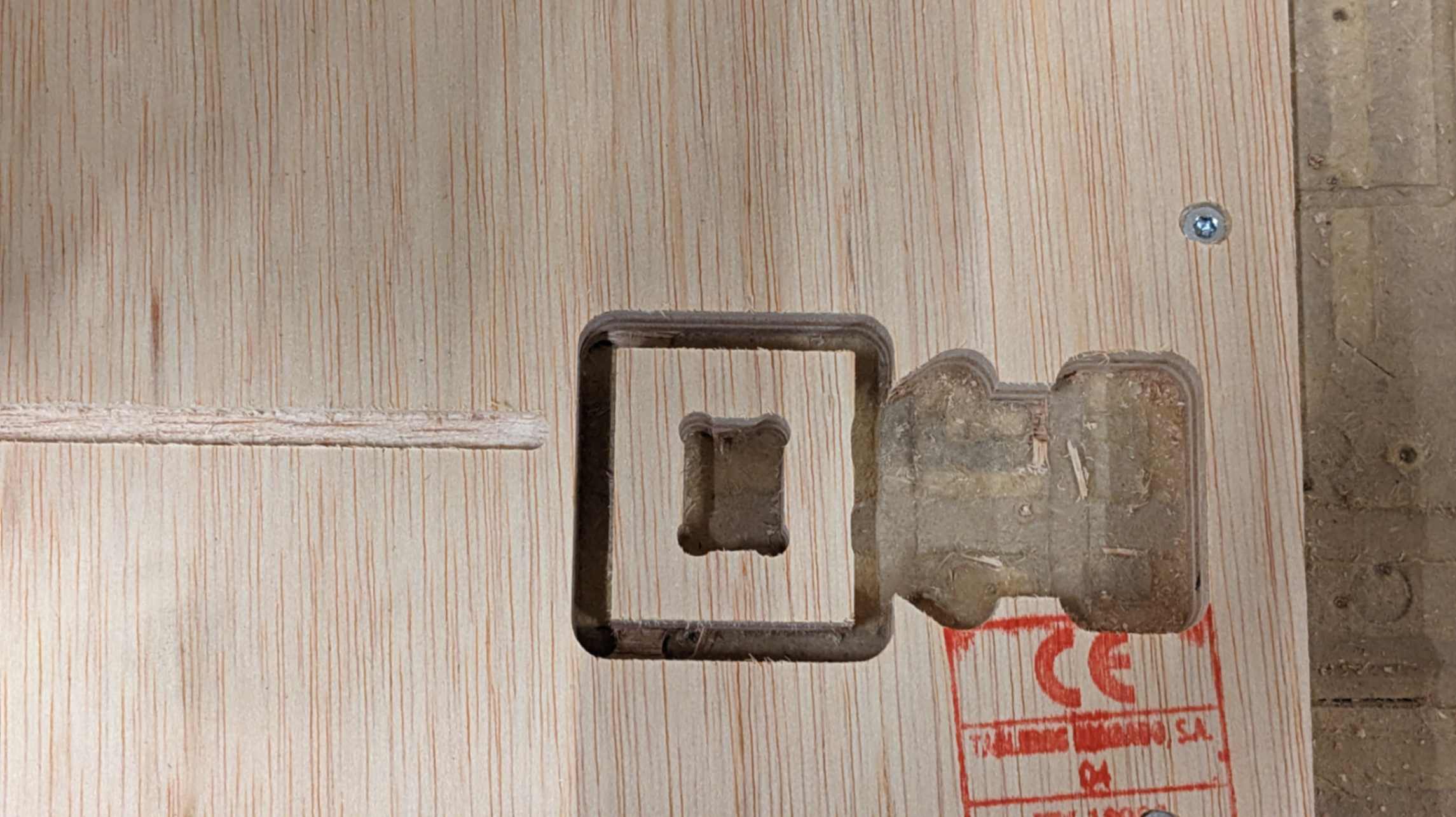
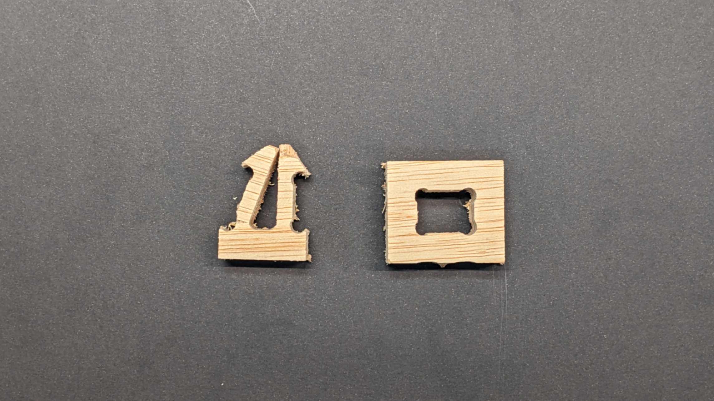
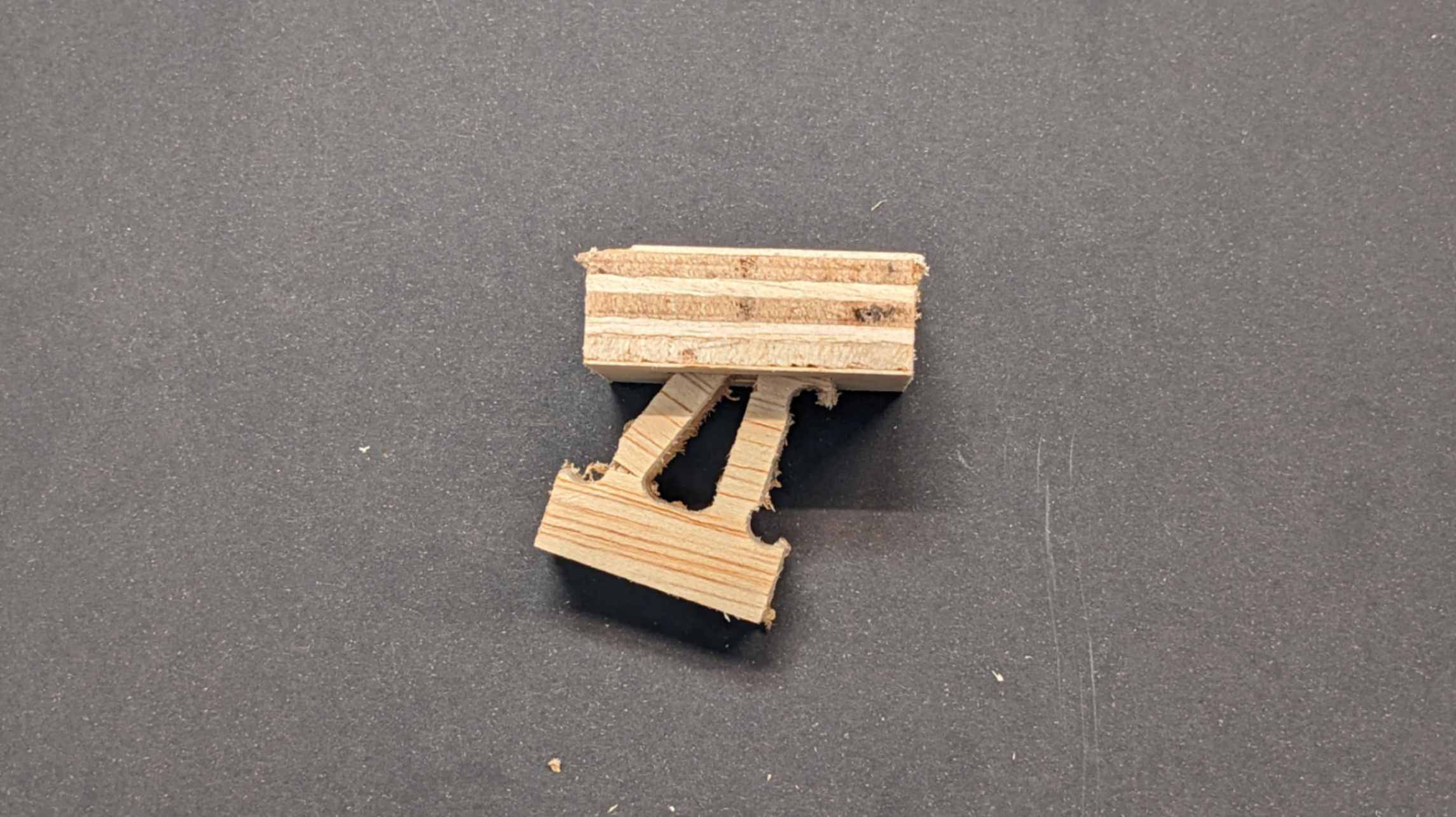
Snap joint was not very successful since it broke when I tried to join them for the first time. From this test, I learned the dimension for the snap joint needs to be more subtle because as material properties, 15mm Plywood is not very flexible. Also, the direction of the grain might have an effect on the direction of bending.
Test 2
Taking the result of the first test, I started to design my chair. As I continued to design the assembly of the chair I started to realise that I needed to test a few more parts that were not sure. So I did another test.
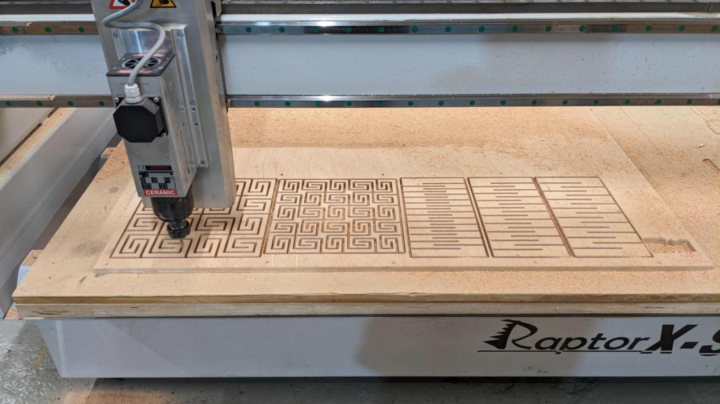
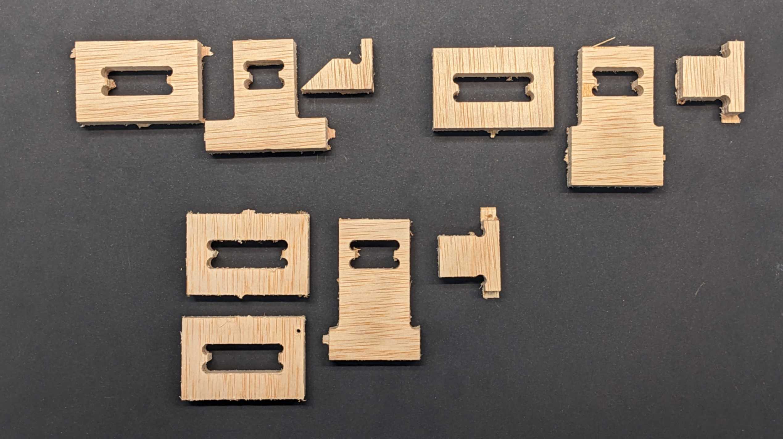
For the second test, I milled 2 versions of scoring (depth of 9.3mm, and 12.4mm), an inverted living hinge pattern, and 3 types of joints. I used the same Gcode setting as the first test and used the milling machine in the same order as I explained above.
Files
01_CNC_flex_test2.3dm
/jpeg-optimizer_01_EamesChair_05.JPG)
Test 2 Result
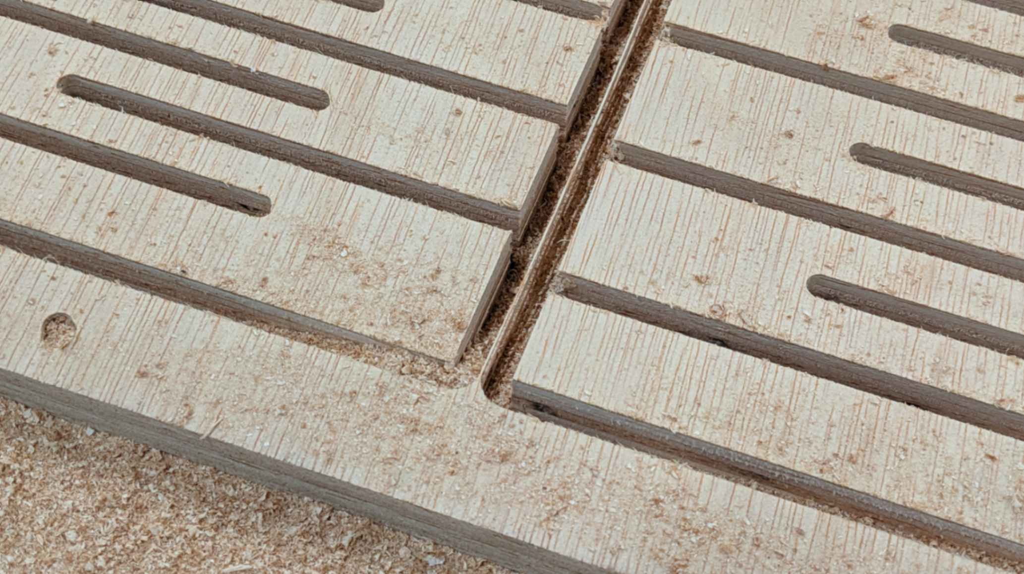
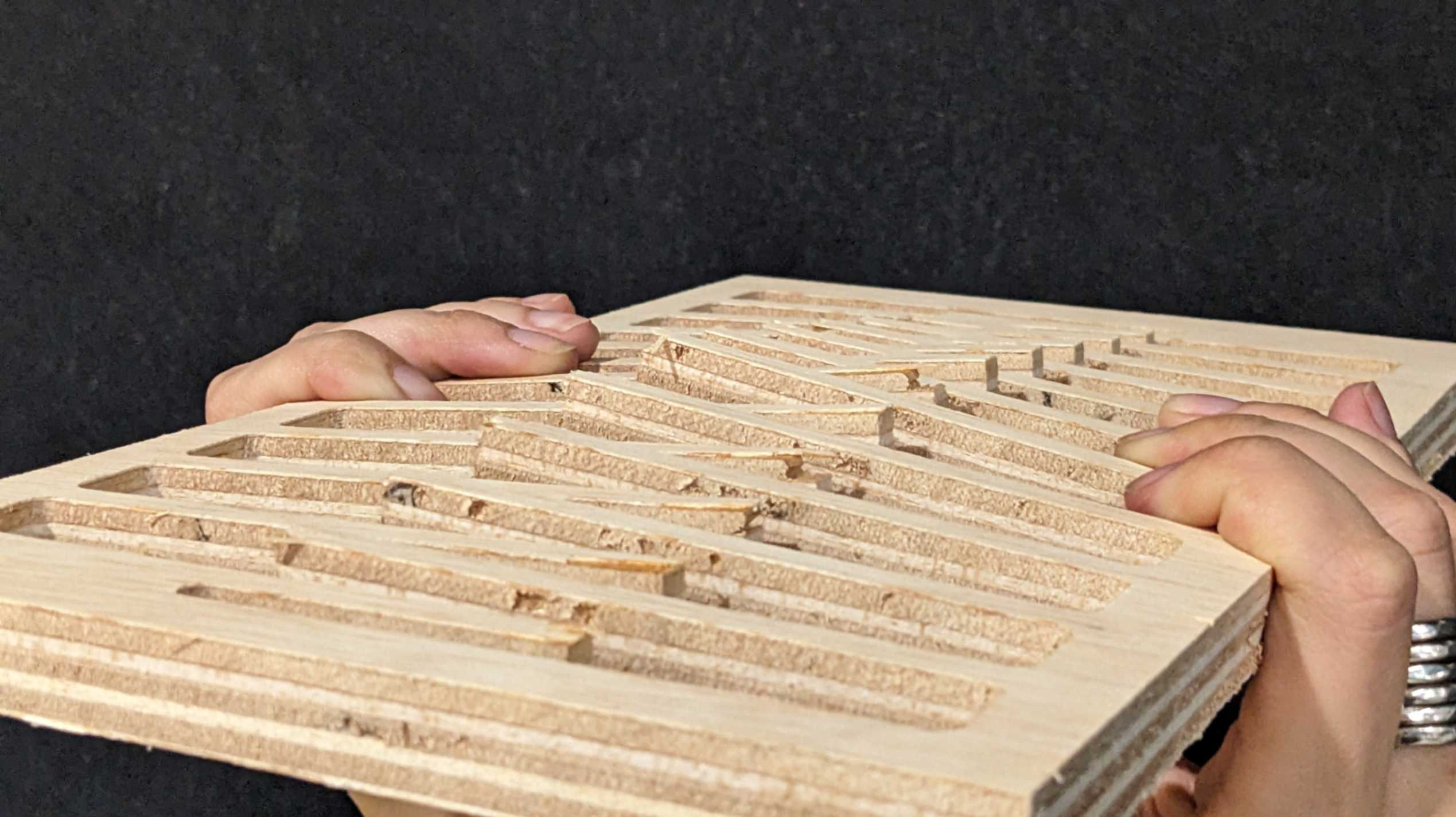
The 2 versions of Scoring was milled nicely. The 12.4mm depth version broke easily when I tried to bend it for the first time. However, it had good flexibility. This can be improved by considering the direction of the grain and also by using higher-quality plywood that has more laminated layers. On the other hand, the 9.3mm depth version was still very stiff, and it only bent a little bit.
The inverted living hinge pattern came out almost as I imagined, but the tip of the sticky part was damaged while the machine was operating pocketing. This can be improved by adjusting the gaps in between. The flexibility was not as much as I thought however this also depends on the size of the piece. I am guessing if the sticky parts are longer, they will bend more. This is also good for future investigation.
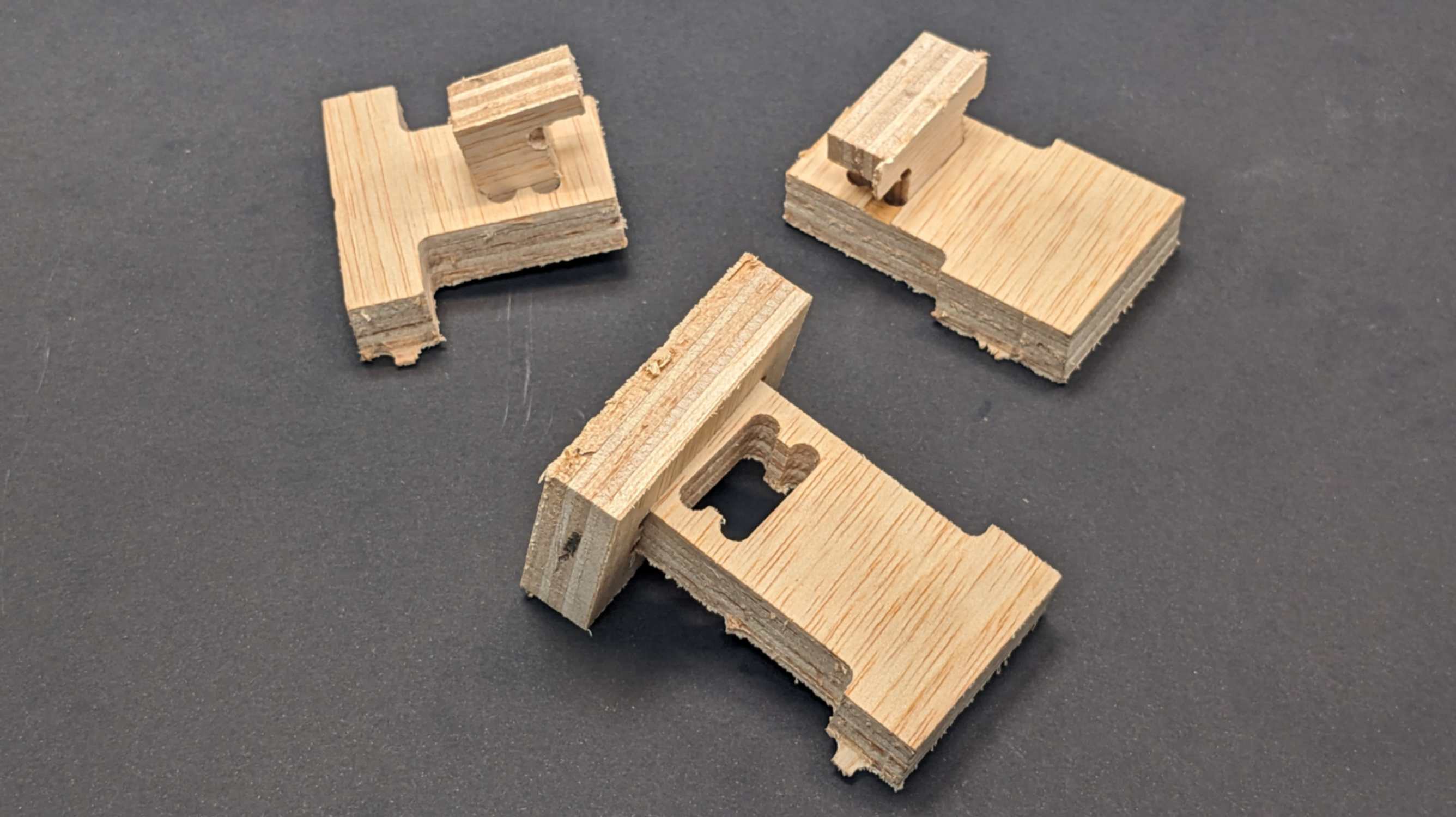
Joints were a complete failure. When milling, there were too few gaps between each piece that they moved during the milling process. This problem is very important to solve because the piece could have popped out from the mining area and damaged its surroundings. Next time I should have more gaps between pieces, especially for smaller pieces. The joinery was also unsuccessful because the tolerance was too tight for a piece to join. It needed to be 1mm or 0.5mm bigger to just fit through. So I will make 2mm or 1mm bigger for the next one just to be safe.
Files
01_CNC_flex_test2_CUT_model.nc
01_CNC_flex_test2_CUT_Standard Drill.nc
I apologise to my tutor Santi for not giving him the satisfaction of breaking my precious pieces.
Chair
After 2 tests I designed a chair with combined different sorts of bending functions. However, when I set the same milling setting as the previous time in Rhino CAM, it calculated 2.5 hours of milling. So I reached out to my tutor to get help. My tutor changed a lot of parameters, mainly the ones that have to be the speed of milling, especially for Engraving and Pocketing which take longer time to mill.
In the end, my tutor managed to reduce the milling time to 1.5 hours. It was the fastest setting for this model. The screenshot shows the detailed parameters for this fast milling setting.
Files
02_CNC_Chair.3dm
02_CNC_Chair_Gcoded.3dm
/jpeg-optimizer_01_EamesChair_06.JPG)
/jpeg-optimizer_00_Tool.PNG)
/jpeg-optimizer_01_Engraving_01.PNG)
/jpeg-optimizer_02_Outline_tabs_01.PNG)
/jpeg-optimizer_02_Pocketing_01.PNG)
/jpeg-optimizer_03_1hour_reduced.PNG)
Chair Result
Milling was done without any issues. I sanded roughly and checked how all the pieces fit together. However, As I was assembling I started to realise a few problems. The problems are below.
- Joints were too loose. This was because I made the tolerance a little bit too big. I think it should be around 0.5mm
- Lower front living hinge broke. It was trying to bend too much
- The Sitting surface broke when I tried to sit on it because it was too flexible.
- Lower back living hinge was bending well but did not much the joint.
- Middle back inverted living hinge was ok but scoring broke. It should have been no scoring or at least 9.3mm scoring.
Files
02_CNC_Chair_Gcoded_Chair.nc
02_CNC_Chair_Gcoded_Standard Drill.nc
/jpeg-optimizer_PXL_20240311_144647966.jpg)
/jpeg-optimizer_PXL_20240311_155120821.jpg)
/jpeg-optimizer_PXL_20240311_155822886.jpg)
/jpeg-optimizer_PXL_20240311_161301885.jpg)
/jpeg-optimizer_PXL_20240311_161410962.jpg)
/jpeg-optimizer_PXL_20240311_161435774.jpg)
/jpeg-optimizer_PXL_20240311_161514404.jpg)
/jpeg-optimizer_PXL_20240311_161557442.jpg)
The only part that went well was the top back living hinge which I used test 1 result to make the curve bigger. In the end, there was no chance for me to use the CNC milling machine again this week because there were many people already book the machine. I will leave this chair for now, but I would love to make the fixed version in the future. From making this chair I learned that I need to understand how the object will bend with the limitation of its material properties, and also consider the relation between movement and size because the living hinge becomes more flexible when the piece is bigger.
/jpeg-optimizer_PXL_20240311_161650126.jpg)
/jpeg-optimizer_PXL_20240311_161717757.jpg)
/jpeg-optimizer_PXL_20240311_161622224.jpg)
Hero Shot
/jpeg-optimizer_PXL_20240311_161243380.jpg)