6. Embedded Programming
In week 4 we learned how to create a pcb and what it is and does. This week we take it one step further. With the Barduino 4.0.1 we get to explore the possibilities of programming.
Furthermore, I created my own pcb and now you can see how i programmed it with the blink code to test it and the code to communicate in serial.
Software
To program the board, a specific software is necessary. Now I'm using Arduino. Another program that could be used isThonny.
Unfortunatly, due to a problem with an unknown license that i can't seem to solve, I decided to continue with Arduino.
To swith softwares from Arduino to Thonny, it is important the reboot the board. To do this, you have to press the "B" and hold it and press the "R" too.
Boot: "B" Restart the board with the "B" pressed.
Reset: "R", this erases the code.
Just like the pcb we made in week 4, it is important to understand and have the Pinout explained.
Excel sheet of the Seed Rp 2040
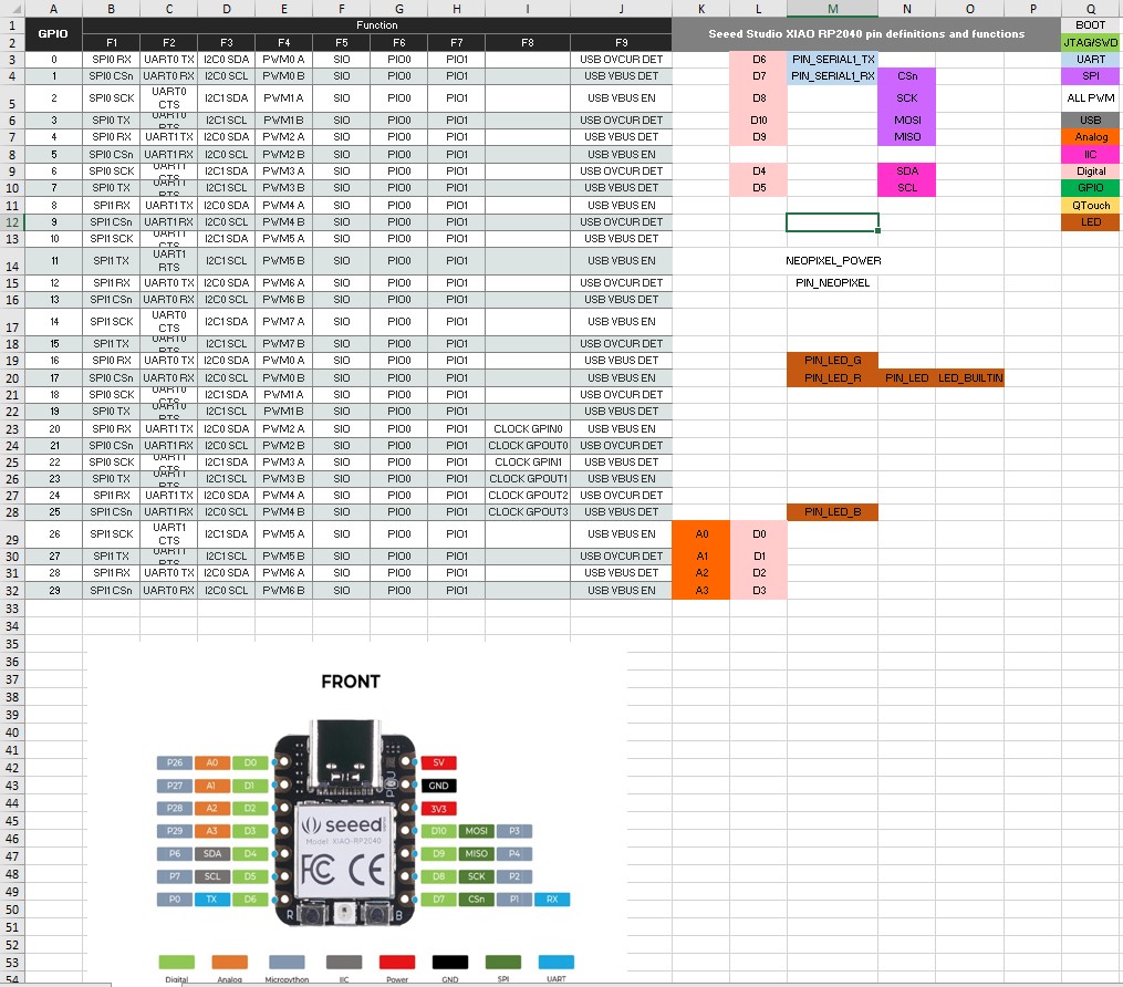
Here you can download the excelsheet for the RP2040
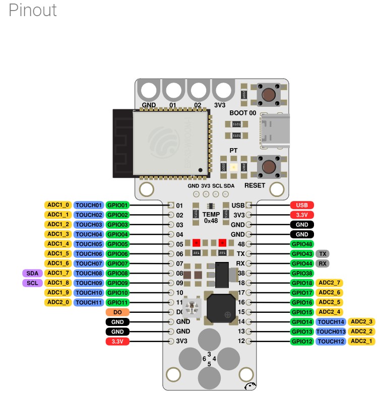
Pinout of the Barduino 4.0.1
Coding
Here's a list of important things in arduino: (Used Chatgpt for this list)
- 1. Setup and Loop:
The setup() function is called once when the Arduino board starts up. It's typically used for initializing variables, setting pin modes, and other one-time setup tasks.
The loop() function runs continuously after setup(). It's where you put the main logic of your program, and it runs in a loop until the board loses power.
- 2. Variables:
- 3. Control Structures:
- 4. Functions:
- 5. Libraries:
- 6. I/O (Input/Output):
- 7. Serial Communication:
- 8. Analog and Digital I/O:
- 9. Memory Management:
- 10. Error Handling:
- 11. Hardware Interfacing:
- 12. Power Management:
Variables are used to store data temporarily in a program.
Arduino supports various data types like integers (int), floating-point numbers (float), characters (char), and Boolean values (boolean).
Control structures are used to control the flow of a program. if statements allow you to execute certain code based on conditions.
while and for loops allow you to repeat code until a condition is met or for a specified number of iterations.
switch statements provide an efficient way to handle multiple possible conditions.
Arduino supports various data types like integers (int), floating-point numbers (float), characters (char), and Boolean values (boolean).
Functions allow you to break your code into smaller, reusable chunks.
You can define your own functions besides setup() and loop(), making your code more modular and easier to understand.
Libraries are collections of pre-written code that provide additional functionality to your Arduino sketches.
They save time by providing ready-made solutions for common tasks such as controlling displays, sensors, motors, and communication protocols.
Arduino boards interact with the physical world through input and output pins.
Digital pins can read/write digital signals (HIGH or LOW), while analog pins can read analog voltages.
Examples of input devices include switches, buttons, and sensors, while output devices include LEDs, motors, and displays.
Serial communication allows the Arduino board to communicate with a computer or other devices through the Serial Monitor.
It's commonly used for debugging, sending sensor data to a computer, or receiving commands from an external device.
Analog pins can read analog voltage levels from sensors, while digital pins can only read/write digital values (HIGH or LOW).
Analog pins are often used with sensors that provide continuous analog outputs, such as temperature sensors or light sensors.
Arduino boards have limited memory for storing program code (flash memory) and temporary data (RAM).
Be mindful of memory usage, especially when dealing with large arrays, strings, or complex data structures.
Seeed RP2040, has a storage capacity for 1.4MB
 There is a limit to the space on the board. In this case, with the Seeed RP2040, there is storage for 1.4MB. There is a way to check the capacity of the board in the program. To do this, you go to the Raspberry Pi Pico, click on the 3 dots and go to storage. Here you can see the total space, used space and free space.
Implement error-checking mechanisms to handle unexpected situations gracefully.
Use Serial.println() statements for debugging and providing feedback.
Understand the hardware components you are using, such as sensors, actuators, displays, etc.
Refer to datasheets and documentation for proper usage and wiring instructions.
Consider power requirements and limitations of your Arduino board and connected peripherals.
Use appropriate power sources and consider power-saving techniques when necessary to prolong battery life or minimize power consumption.
Testing the board
With the Barduino board, there are many things to try out.
Neopixel, buzzer, touch, photoresistor, phototransistor, temperature, etc
This is the example of the temperature test:
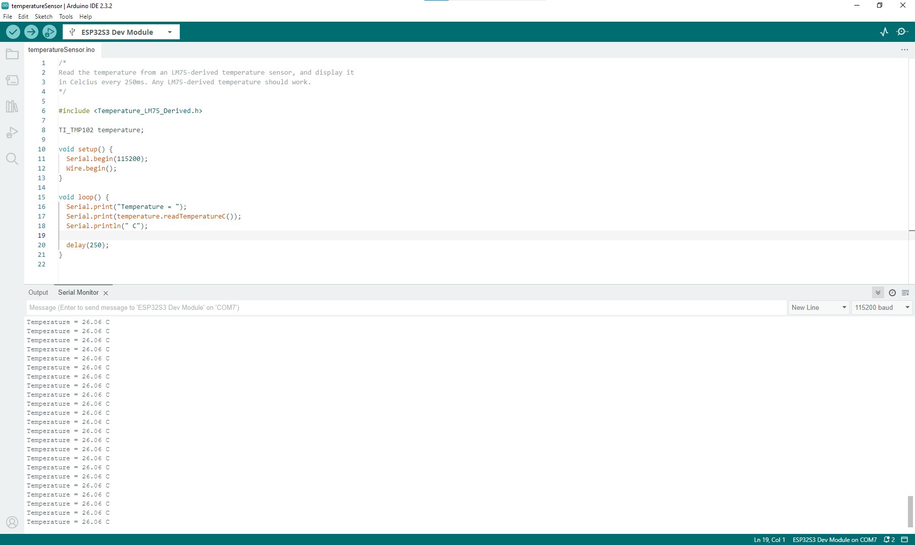
With the written code, it is possible to receive information from the board and read it.
As you can see, it is 26°C (in the classroom!)
Code explanation
This code uses an external library called "Temperature_LM75_Derived.h" to interface with a temperature sensor. The sensor being used here is a TI TMP102 temperature sensor.
In the setup() function:
The code initializes serial communication with the computer at a baud rate of 115200 bauds per second using Serial.begin(115200). It also initializes the I2C communication bus with Wire.begin(). This is necessary because the TMP102 sensor communicates over the I2C protocol.
In the loop() function:
The code continuously reads the temperature from the TMP102 sensor and prints it to the serial monitor in the Arduino IDE. It prints a message "Temperature = " followed by the temperature value in degrees Celsius obtained from temperature.readTemperatureC(). It then prints " C" to indicate that the temperature is in Celsius. After printing the temperature, it waits for 250 milliseconds (delay(250)) before repeating the process.
So, overall, this code continuously reads the temperature from the TMP102 sensor and prints it to the serial monitor every 250 milliseconds.
Code for measuring the temperature
#include Temperature_LM75_Derived.h

  TI_TMP102 temperature;

  void setup() {
    Serial.begin(115200);
    Wire.begin();
  }

  void loop() {
    Serial.print("Temperature = ");
    Serial.print(temperature.readTemperatureC());
    Serial.println(" C");

    delay(250);
  }
Testing my own board
In week 4 I created this dev boardwith the ESP32s3wroom1 microcontroller. The reason for choosing this microcontroller is that this might be the one i will use in the final project!
Test with the blinking program:
    const int LED = 21;
// the setup function runs once when you press reset or power the board
void setup() {
  // initialize digital pin LED_BUILTIN as an output.
  pinMode(LED, OUTPUT);
}

// the loop function runs over and over again forever
void loop() {
  digitalWrite(LED, HIGH);  // turn the LED on (HIGH is the voltage level)
  delay(1000);                      // wait for a second
  digitalWrite(LED, LOW);   // turn the LED off by making the voltage LOW
  delay(1000);                      // wait for a second
}
This is a video of the blinking LED on my board.
Test with the serial communication with the blinking led: here the board will communicate in serial if the led is on or off. The led has a delay of 3000ms when it is on and turns of for 1000ms. You can see this in serial.
        const int LED = 21;

        // the setup function runs once when you press reset or power the board
        void setup() {
          // initialize digital pin LED as an output
          pinMode(LED, OUTPUT);

          // initialize serial communication at 9600 bits per second
          Serial.begin(9600);
        }

        // the loop function runs over and over again forever
        void loop() {
          digitalWrite(LED, HIGH);  // turn the LED on (HIGH is the voltage level)
          Serial.println("LED is ON");
          delay(3000);              // wait for a second

          digitalWrite(LED, LOW);   // turn the LED off by making the voltage LOW
          Serial.println("LED is OFF");
          delay(1000);              // wait for a second
        }
This is a video of the serial communication with the blinking led.
Test with the serial communication with the button and led: here the board will communicate in serial that when i press the button, the led must go on and when the button is released, the led must turn off.
            const int LED = 21;
            const int BUTTON = 0; // GPIO pin for the button


            void setup() {

            pinMode(LED, OUTPUT);

            // initialize digital pin BUTTON as an input with pull-up resistor
            pinMode(BUTTON, INPUT_PULLUP);

            // initialize serial communication at 9600 bits per second
            Serial.begin(9600);
          }

            // the loop function runs over and over again forever
            void loop() {
            // read the state of the button
            int buttonState = digitalRead(BUTTON);

            if (buttonState == LOW) { // button is pressed (active low)
            Serial.println("Button is PRESSED");
            digitalWrite(LED, HIGH); // turn the LED on
            } else {
            Serial.println("Button is NOT pressed");
            digitalWrite(LED, LOW); // turn the LED off
            }

            delay(1000); // wait for a second
            }
This is a video of the serial communication with the button and led.
Useful links
Stuff i need to check and do:
PWM=Pulse Width Modulation
Adafruit neopixel website info