4. Electronics Production
- Creating PCB's with the Roland SRM-20 monofab machine.
- Learn how to solder and add components like LED to the PCB.
PCB
A pcb is Printed Circuit Board that we find in every product that has some electronics. It is in this case made out of copper because copper is a very conductive material.
PCB's are circuit boards consisting of alternating layers of conductive and non-conductive material. The inner conductive layers feature copper etchings that allow power and signals to pass to connected circuit components.Create the PCB
To be able to create the PCB, it is important to have the design converted as a png.
With this website: modsproject you can create the file that you need for the machine.
You import the png of the design and check the parameters like the speed, the type of endmill and the origin.
First you start with the traces, then with the holes and then with the outlines.
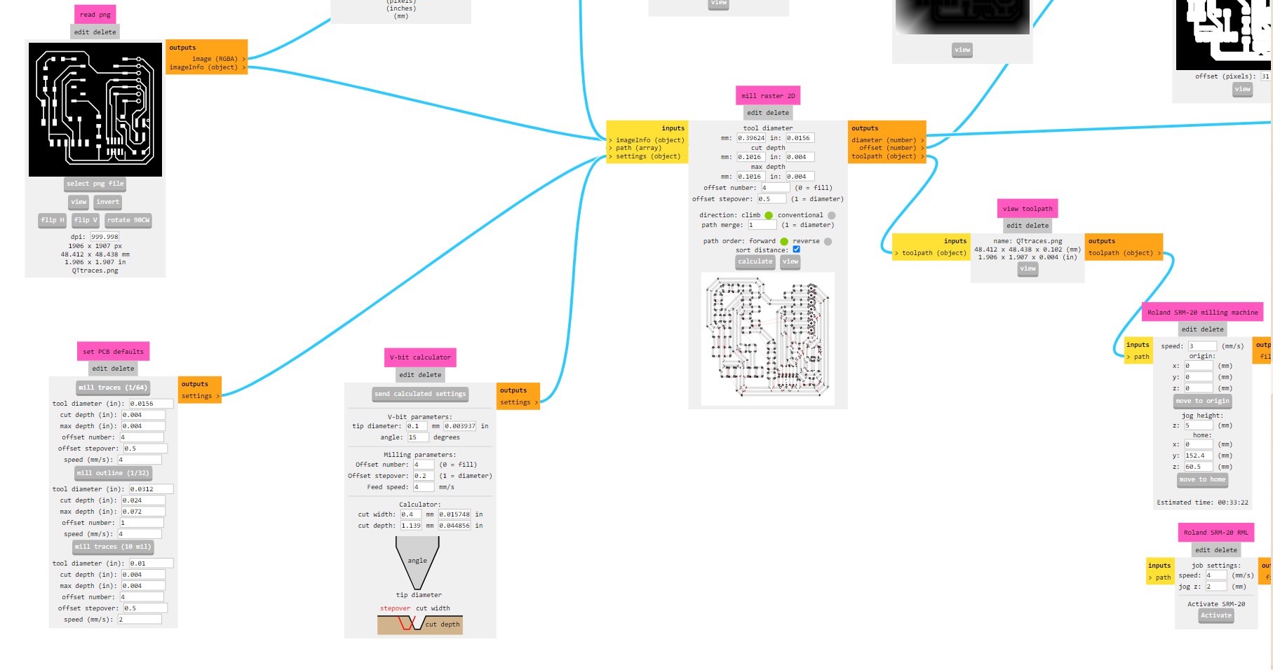
Once the parameters are set, you can calculate the path and download the file. The files are in .rml
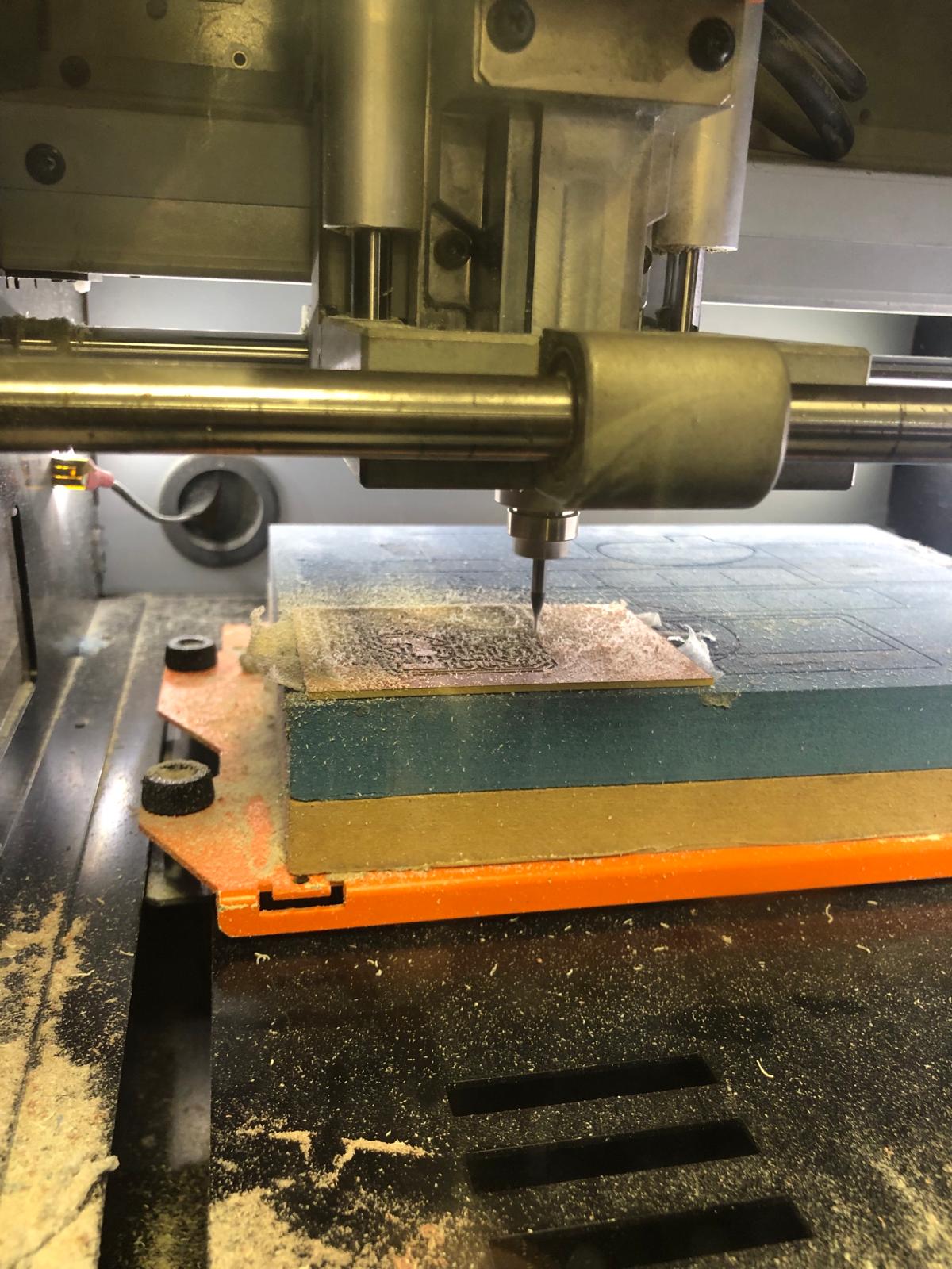
After uploading the files onto the drive, you can start the proces with the machine.
In order to start, it is important that you define the Origin and the Z axis for the height and the type of endmill you need to use.
- For traces: 1/64, speed: 3, origin: 0.0.0 and jog height: 5 depth: 1.75
- For holes: 1/32, speed:1.5, origin: 0.0.0 and jog height: 5, depth: 1.75
- For cutting (outline): 1/32, speed 0.5, origin: 0.0.0 and jog height: 5, depth: 1.75
Once the Origin and height are set, the machine can start. As you can see on the picture, there is a lot of dust that gets generated.
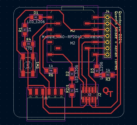
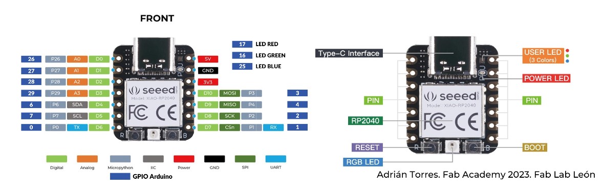
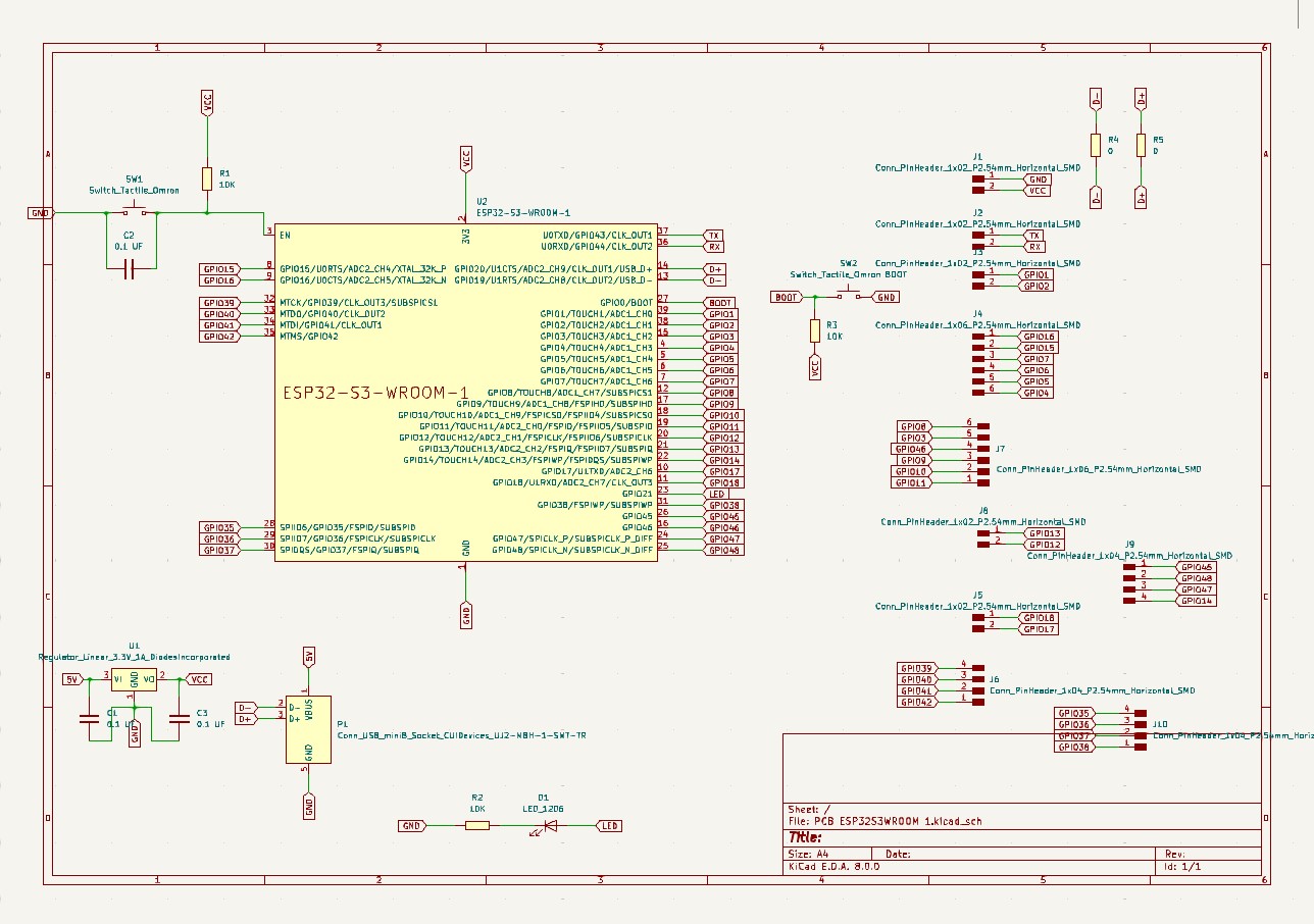
Schematic pcb and info board
This is the schematic of the pcb with the components.
This is the info about the board.
Soldering components
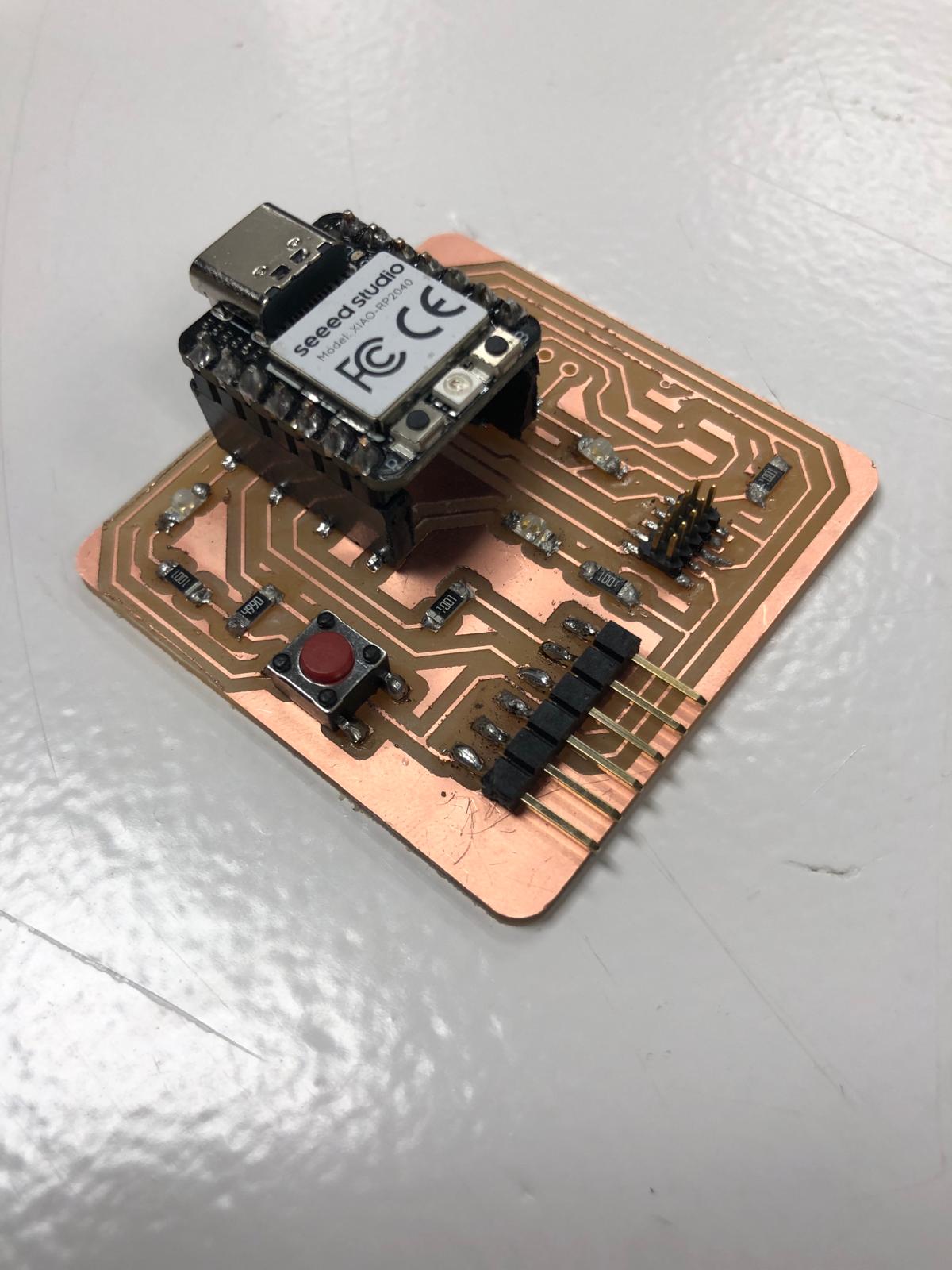
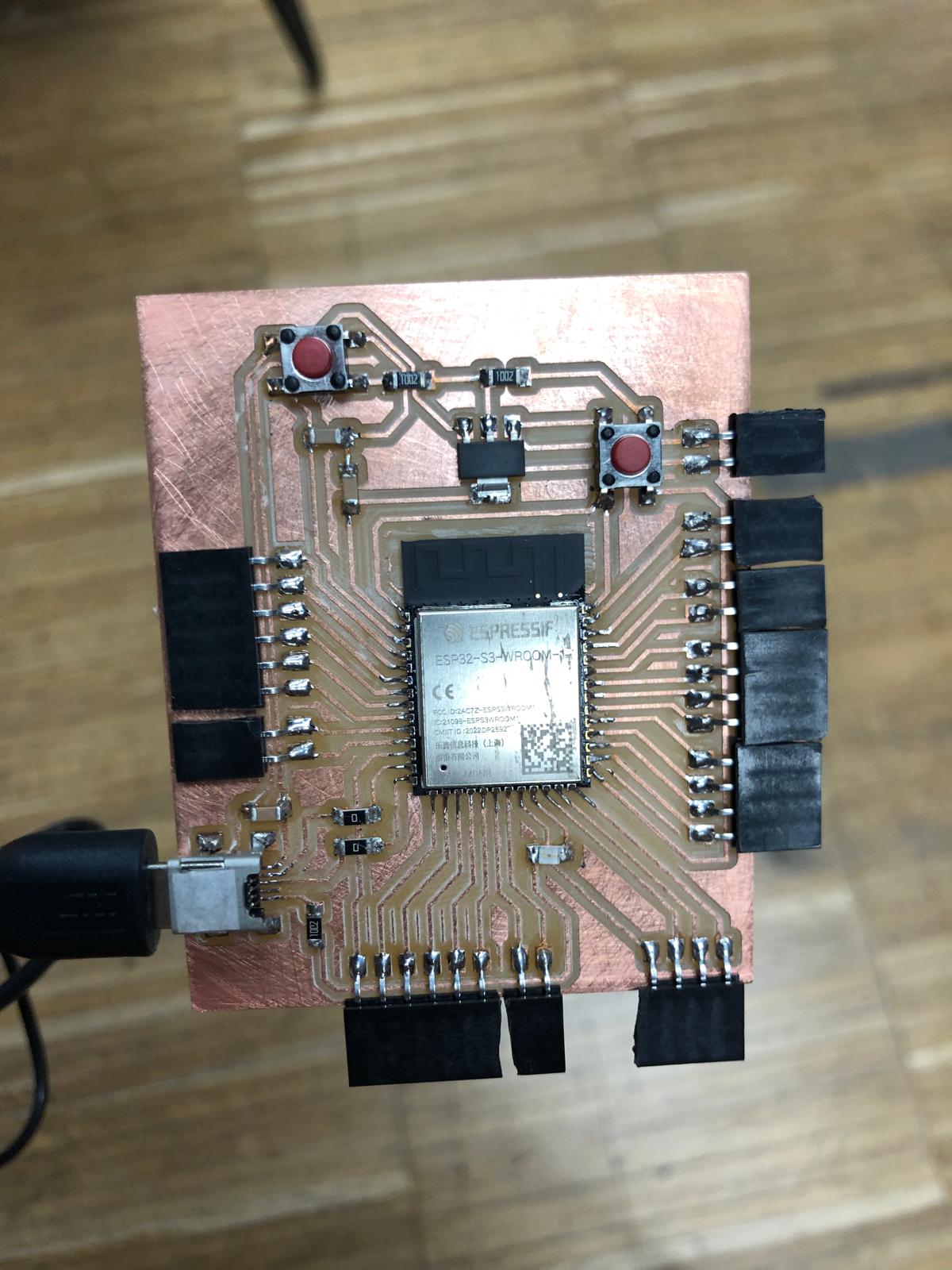
Now that the PCB is ready, it is time to add the components. Adding components can be done by soldering.
The soldering went quite good, just takes a long time :p
Unfortunatly I did not take any pictures during the soldering (too concentrated) but this is the end result:
Arduino
The pcb is ready and needs to be programmed. The programming needs to be done with Arduino. To start, I needed to download the Arduino program. I downloaded it from this page: Download arduino
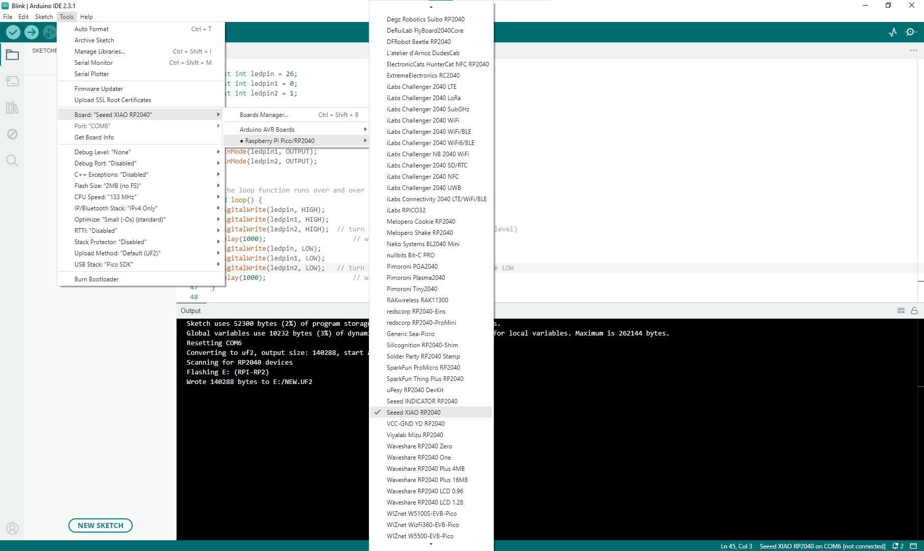
It is also important to install and configure the correct programs to be able to code the Seeed XIAO RP2040 board.
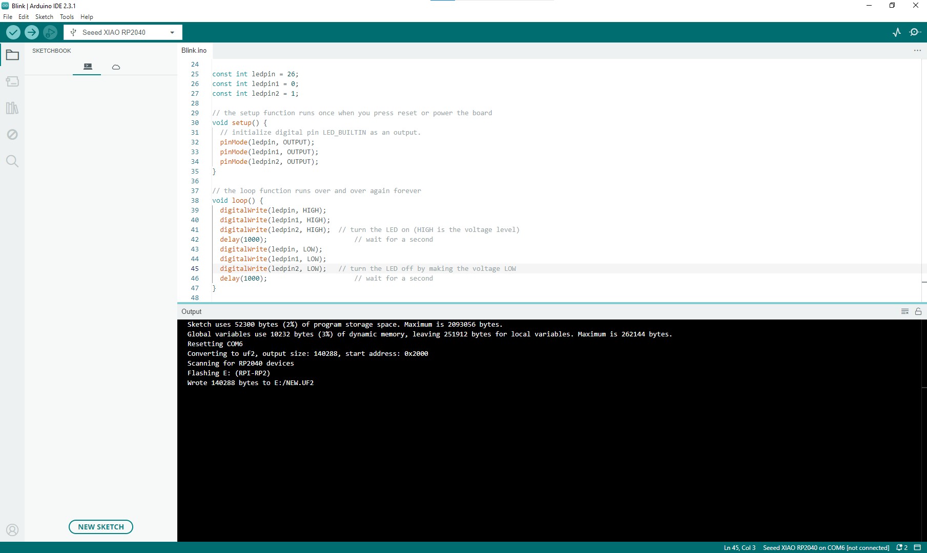
Now that the board is installed, we can try the Blink program. With this it is possible to test all the LED's. This is the code I used to make the 3 LED's blink every second.
Result
Here you can see the result of the blinking lights!
Button
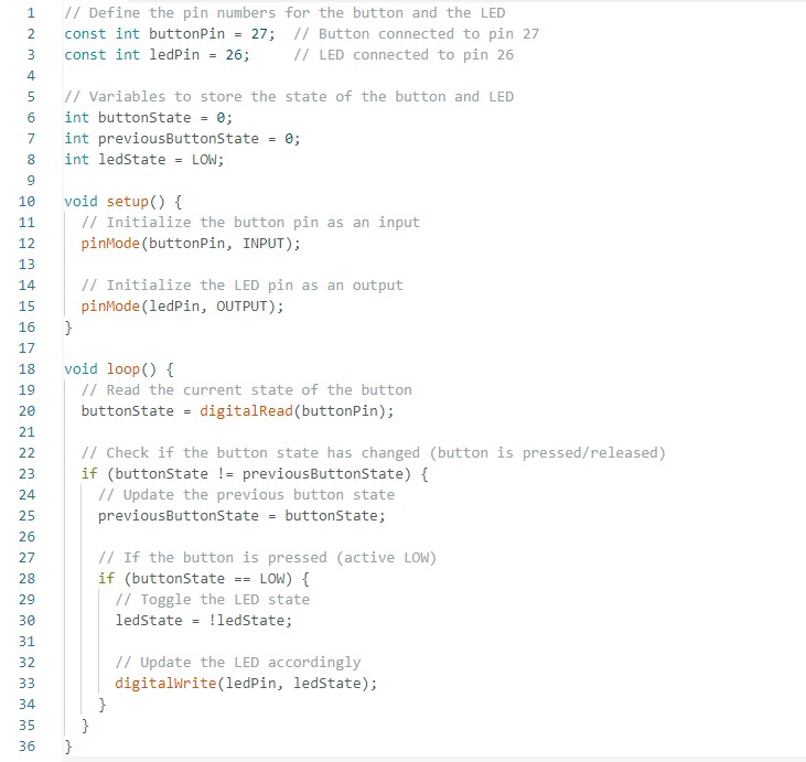
To test the button, and make the LED go on or off when the button is pressed, I used Chatgpt to create the code.
This is the code that Chatgpt created:
Result
Here you can see the result of the button that turns on/off the LED!
files
modsproject + png traces, outline and holes
Own dev board
I made my own dev board, where i expose all of the pins of the microcontroller esp32-s3-wroom-1.
Kicad
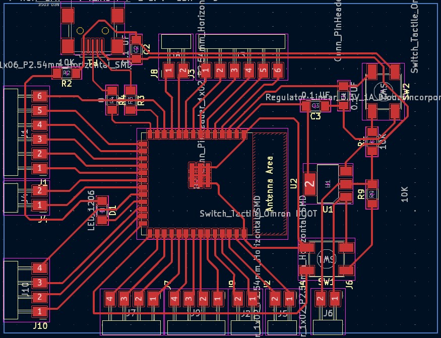
Pictures
This is the file
First boardmodsproject + png traces, outline and holes
Dev boardkicad files+modsproject + png traces, outline and holes