10 Mechanical design & machine design
This week's assignment Design a machine that includes mechanism + actuation + automation + application, build the machine and operate it manually as well as actuate and automate the machine.
Group assignment: A paste printer
The documentation for ROTA - a polar paste printer can be found here.
Individual contribution: Assembly and structural/systemic improvements
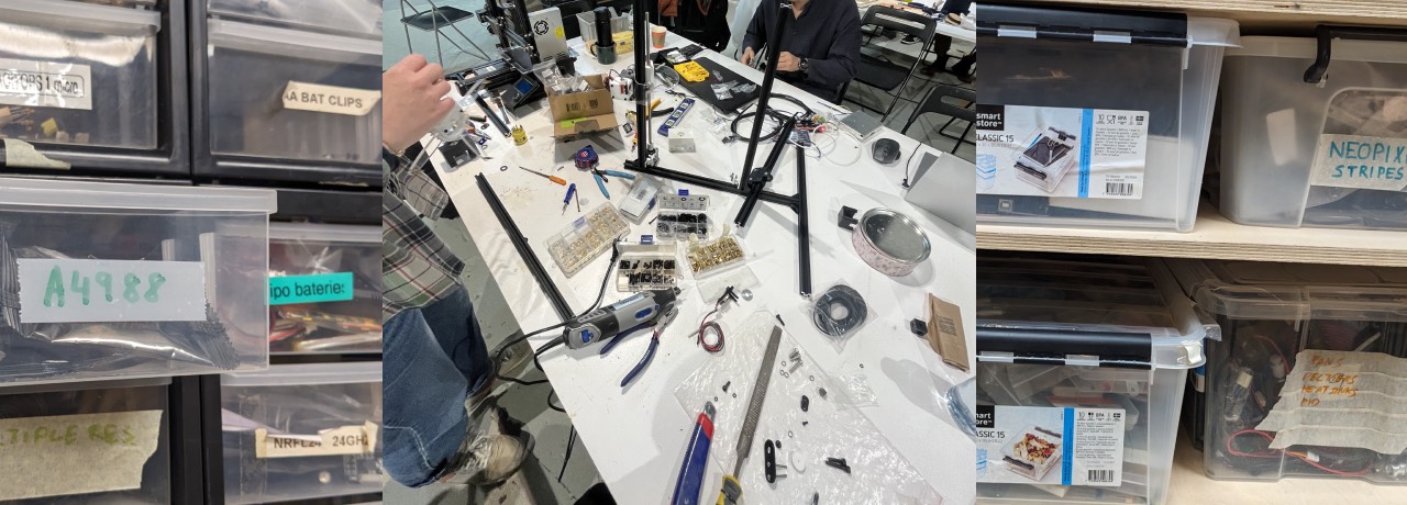
The first couple of days of machine week I lay in bed with the fever and worked remotely on the initial documentation. Once I arrived we had a rough plan for the assembly and an initial set of 3-d printed pieces ready. In general I would say we worked very well as a team and used the power of the group to ping-pong ideas, discuss and improve along the way. I would describe myself in the group as the "Fixer", aiming for an ugly working prototype and understanding the real-life measurements and tolerances before redesigning on the computer, as well as pushing for a minimum set of features before perfection.
Main challenges we faced in the assembly were:
- conversion of perfectly fitting pieces in 3D to mounting them on the adapted aluminium frames
- tolerances and distances during alignment of the pieces
- material struggle: yes everything can be 3D-printed, but not always is the ideal solution
Conversion 3D-model to assembled machine
Since we were matching pieces of a perfectly aligned and adjusted machine, the RepRap or our lab's paste printer, with literally the pieces we found in the lab. We experienced several hickups.
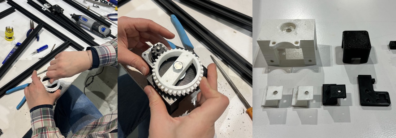
The base had to hold the Y-axis motor and stabilize the bed. We faced the issue that the motor was adding quite some weight to the piece and therefore tension to the small and maingrain of the rotational bed. We had already reprinted, so in order to save time, and avoid another "graveyard piece" we tried to manually fix it: we sunk some screws using the soldering iron, we scraped off some material for the motor to be more straight, changed the washers several times, changed to longer screws, drilled holes to fix the bed stabilizer to the bed, changed the washers again, added locknuts and moved the grains more to the top.
Eventually we arrived with a nice result - in a redesign the motor should be sitting on material to release pressure from the grains and be sunk in a little to the base. Furthermore it should be fixed at all four points.
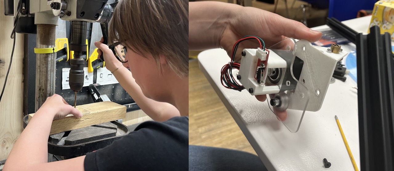
Another example of a perfectly fit piece in the model is the rodholder - we didn't take into account how we would fix the Z-axis motor to the aluminium frame. Thus in the first addition the rod was not in an 90° angle, which not only hindered the rotation but also wore off the material, until the piece actually broke. So we had to reprint and add thickness as well as add several spacers to bridge the gap. We also added holes to the lasercut piece - on the first try we did not take into account that the screw had a thickness as well and needed to be placed exactly in the middle of the aluminium frame.
Tolerances & distances
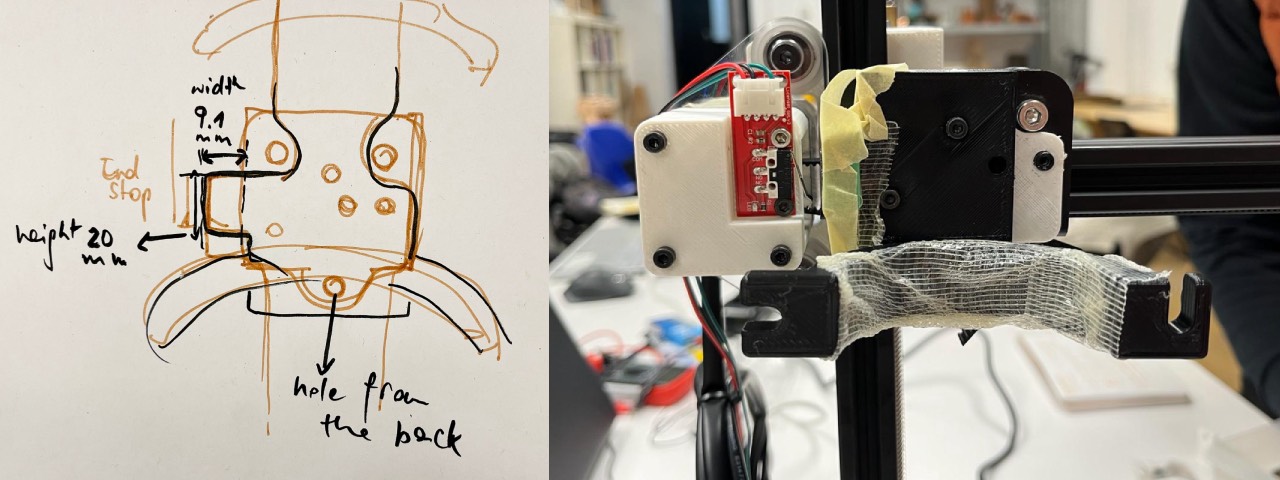
"Let's mount it at 9.95 mm" is something we would all say at some point in the assembly - realizing that we sometimes did not even have the tools physically available to mount it in that way. Personally that was a great lesson to keep switching between modelling digitally and physically. Many design features we actually had to see - tape pieces in a rough way, measure, model, print only to realize because we had changed another piece, to remodel it again.
The cartridge holder for example was a great example that we had not taken the sourroundings into account. The cartridge was adding space to the front - obviously!, disaligning the bed and potentionally hitting the frames that held the bed. This is why we had to extend the piece in order to hit the X-axis endstopp without crashing into the pole.
Material struggle
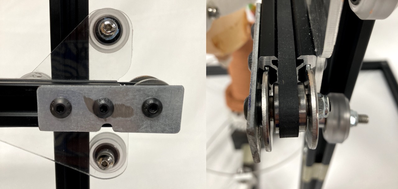
One of my personal struggles was to navigate the lab's ressources. Everything could be found, but it was rather a scavenger hunt! Especially for the belt tensioner we were looking for a bearing that would smoothly rotate, but keep the belt in place. Additionally the washers needed to be small enough not to touch the bearing but thin enough not to add extra distance for the bigger washers to hold the belt in place.
Also learning from our lab's paste printer is was sometimes tough to accept, we just could not fabricate everything, but had to go back to "traditional" workshop ways: drilling and cutting metal scraps, so the bearing would not touch the frame. The 3-d printed pieces could simply not stand the pressure.
I wish we had taken a correct list of all non-printed parts we used. Now we would have to dissassemble to know!
Lessons Learned
- absolute appreciation for kits and well ordered/labelled boxes
- assembly roughly before redesigning and reprinting
- better done than perfect to the limit
- victories need to be celebrated as well!