07 Computer controlled machining
This week's assignment is to test runout, alignment, fixturing, speeds, feeds, materials and toolpaths for your machine and make (design+mill+assemble) something big.
Group assignment: Computer controlled machining
The documentation for our group assignment from the Barcelona node can be found here.
Lessons Learned
- touch the flute only on the top part, not to make it oily and less sharp
- x and y axis are rotated to handling the machine from one side, keep that in mind!
- don't stand in front of the machine and wear safety glasses over your glasses!
- Rhino CAM is not available for MAC OS
The boat that rocked
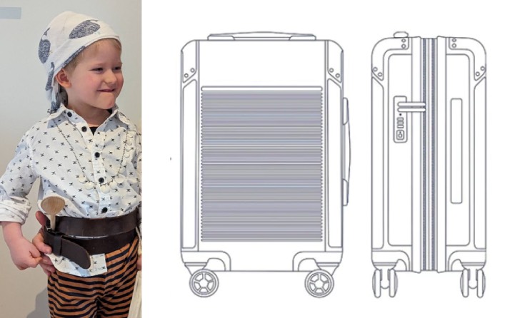
The assignment was to make something BIG and my nephew's third birthday is coming up soon I want to create a pirate boat for him. Since he lives in Austria, the unassembled boat parts need to fit into my suitcase. This meant I had two constraints for the design:
- luggage size: L63cm/W43cm/D28cm
- weight: ~20 kg
1. Design
Understanding proportions
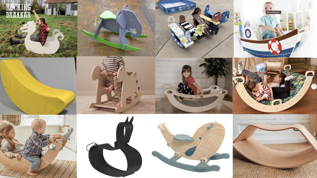
Having some restrictions on the design was already a bit tricky, but I also had to understand the measurements for kids furniture to get a grip on the first sketches. I searched instructables.com for "Rocking Toys" and did a quick Google search for "kids rocking toy". As a kid I had loved IKEA's Mane banana, which was quite small in width and the world of rocking toy is vast. I liked the Montessori arch best proportion wise, as well as the duality in use.
As a conclusion the rocking boat should be approximately ~30-40 cm deep, ~90-100cm long and between ~35-45cm high.
Design for waffle
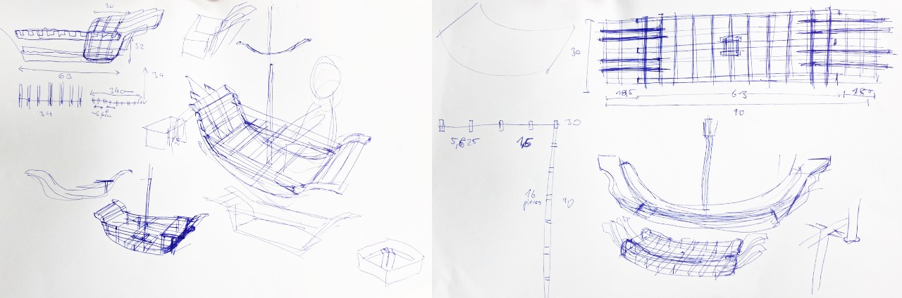
The boat really needed to be stable and pack up flat - that's why I decided to go for the waffle system. While sketching I quickly realized that I was not gonna understand the waffle or proportions without a model. Thus I started cutting a cardboard model of the boat.
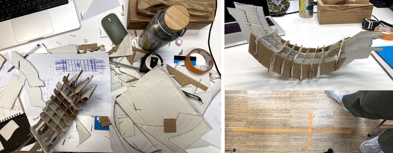
It was a mess but really helped me to understand the keypoints of the design: how many sideplanks are needed for stability?, how can I reach 90 cm width
with separate parts, how could I stack the different pieces into each other? Thanks
Digital model and test
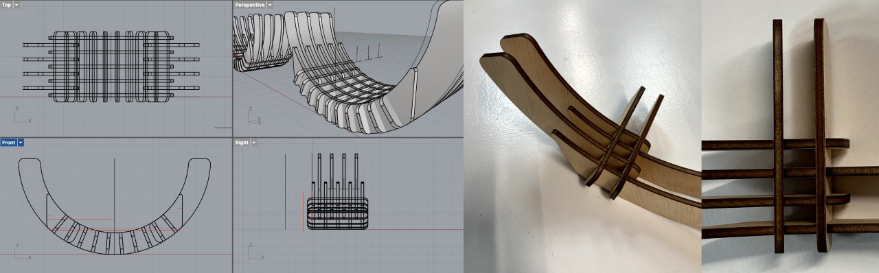
To jump to a more accurate prediction as well as the blueprint for milling I started to model the boat in Rhino. The angle of the planks needed to be precisely and I lacked the visual representation of measurements in Rhino. The lasercut test confirmed that the concept would work, but also revealed that the model was not precise enough.
Switch to Fusion360
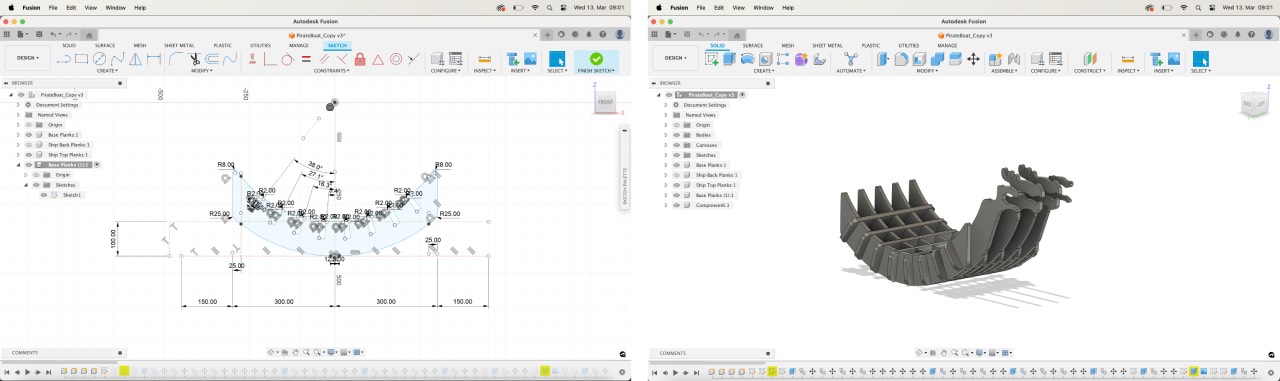
In Fusion I was able to define the angles precisely on the sketch and adapt it during the workflow. The file can be found here. First I defined the baseplanks and copied the angled slots to the sideplanks. To fix the sideplanks I had to choose a crossingplank with 9 instead of five slots.
Really the only downside to Fusion was that my file crashed twice, when I tried to edit the sketches. I was able to recover an older version, but lost time and patience. Especially getting the dogbones with an automated plug-in turned out to be tricky.
I started out with this Dogbone Plugin but not only was it tricky to install because I was not able to find
~/Library/Application Support/Autodesk/Autodesk Fusion 360/API/AddIns this folder on my own on the MAC. Thanks
Prepare Rhino file and nest
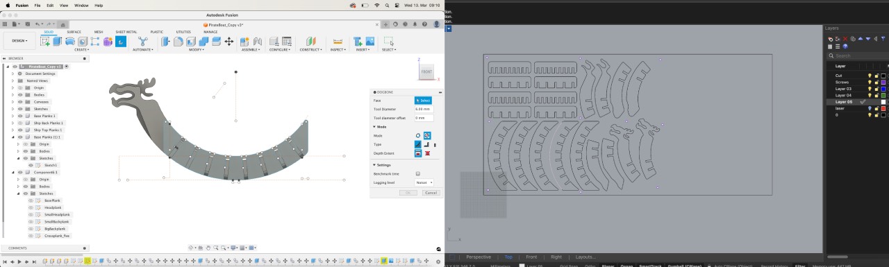
Once I had the dogbones on my sketch I was able to project the outlines into a new sketch in Fusion and export this sketch as an .dxf file and
open it in Rhino. I repeated this process with all my different parts for milling and nested them into the sheet size (2500x1220 mm).
- Before opening Rhino CAM put your different milling "jobs" on different layers. In my case I had Holes, Test, Cut as well as the sheet/box size.
- Change the X/Y axis to match the orientation of the CNC machinse. So I flipped my design 90°.
- Move the lower left corner to 0/0/0.
Rhino CAM
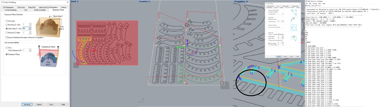
The RhinoCAM Plugin used in the Fablab BCN is a Widows-only plugin. Thus I used a computer in the lab to prepare the CAM file. With the help of the lab staff and my fellow fabacademy students I followed this proposed workflow. The Rhino file can be found here.
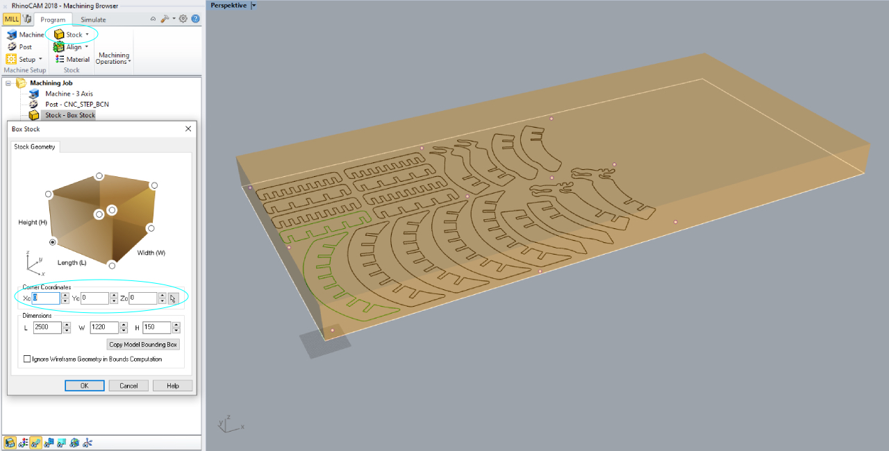
First define the size of your sheet of wood under Program/Stock/BoxStock - keep in mind to set the right heigth of the sheet!
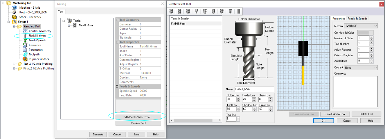
Second define all the drillmills used in the job and select the right one for each process. I used the flat 6mm endmill for both drilling and cutting.
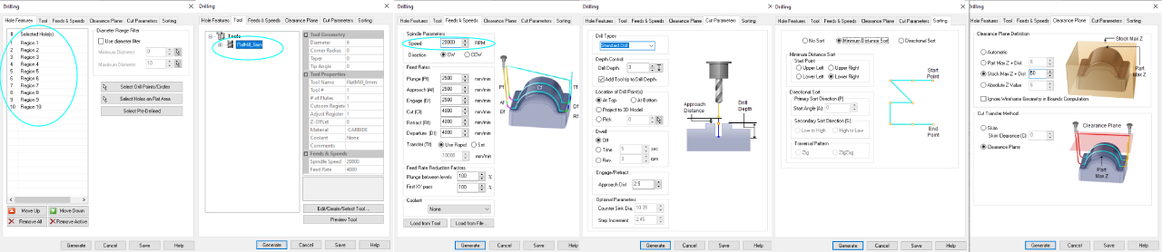
Than create a job for each process: holes, test, cut and define the settings. After selecting the geometry, chose the endmill and define the feeds and speeds. I used 200 000 RPMs (speed), a feedrate of 2500 and a cut depth of 3mm - because these settings are recommended from the lab. Remember to add the 3 mm to the total cut depth to be sure to cut all the way through.
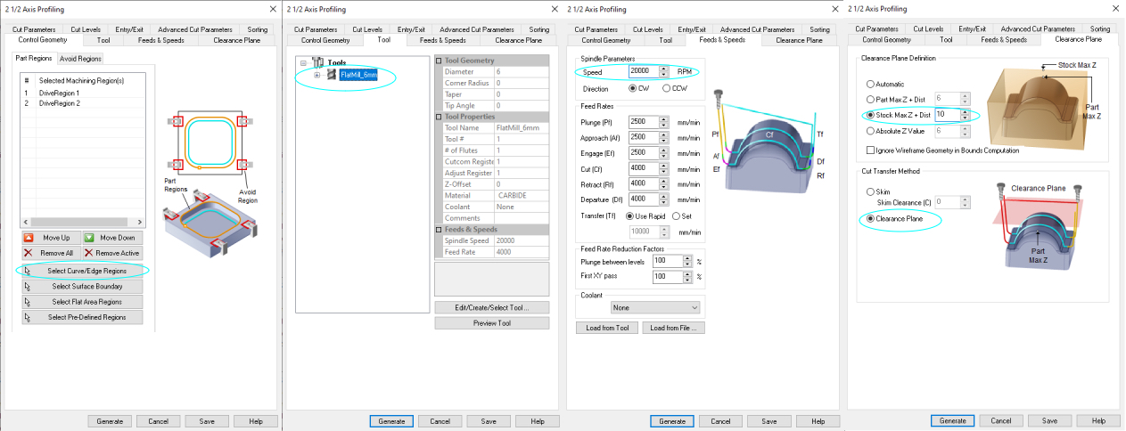
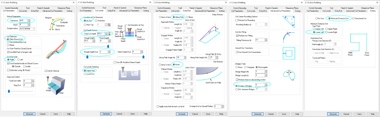
For the cut the adjustable settings were a little more - I choose a Climb/Down Cut because the test in the group assignment gave the best result. Keep in mind to choose Along path
for entry and exit to avoid a crash.
My most important lessons learned were:
- a good starting point is a file of someone that has already cut (e.g to copy the mill specifications)
- first tell the machine what to detect aka define the "Box Stock": keep in mind the measurements! (initially my board was set to 150 mm instead of 15mm)
- define your different job profiles: if you use the same milling procedure (e.g. Cut) you can copy the job and change the selection
- check the milling path with simulation
- check the location of your bridges to easily remove them from the board (I choose to add one more bridge for this reason)
- post the
.ncfiles and put them on the cloud to access from the computer installed close to the CNC machine
NC files:
2. Mill
I used the Raptor X-SL 3200/S20 CNC milling machine, that is operated by the KinetiC-NC software. Thanks @Philip for the support!
Preparation
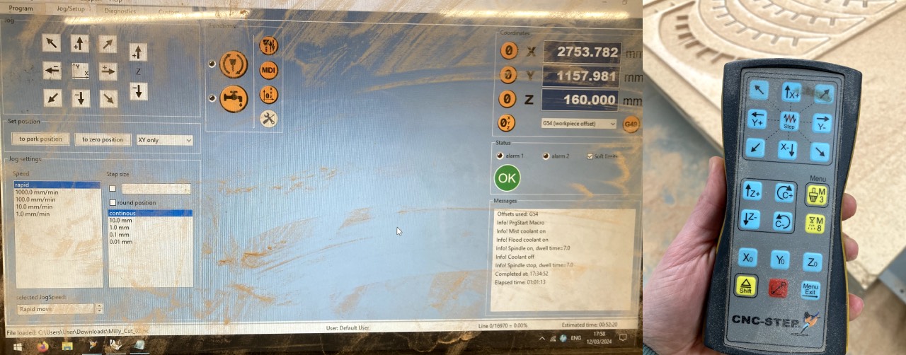
- Align the plate in a 90 degree angle.
- Zero the X and Y by eyeballing the lower right corner and press 0 on the software.
- Zero the Z by lowering the drill mill until approximately 5 cm to the plate.
- Move the remaining 5cm down with the remote control until the bit engraves a little bit into the plate and press 0 on the software.
Fix the sheet to the baseplate
- Start with the Holes file - it will engrave the holes for the screws.
- Fix the screws to the base plate. Screw 2/3 move up again and then fix them all the way.
- Redo the Z on the fixed plate.
Testfile & Cut
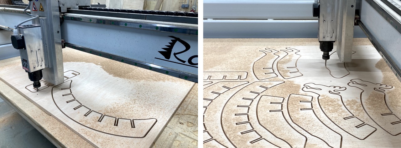
I was not sure about the tolerance of the waffle design I followed @Josep Marti's advice to put a tolerance of 5mm and do a test file of the main and crossplank of the waffle. I loaded the test file and ran it on the CNC mill and than used a chisle to break the brigdes. The joining turned out to be a bit loose but fine. The general advice in the lab was to rather keep it a bit loose and worst case glue a little but every here and there.
Since the test turned out fine I continued the final cut and after around an hour it was done.
Finishing
- Remove the dust from the plate and machine.
- Break the bridges with the chisle.
- Unscrew the plate.
- Sand the remaining bridge pieces off.
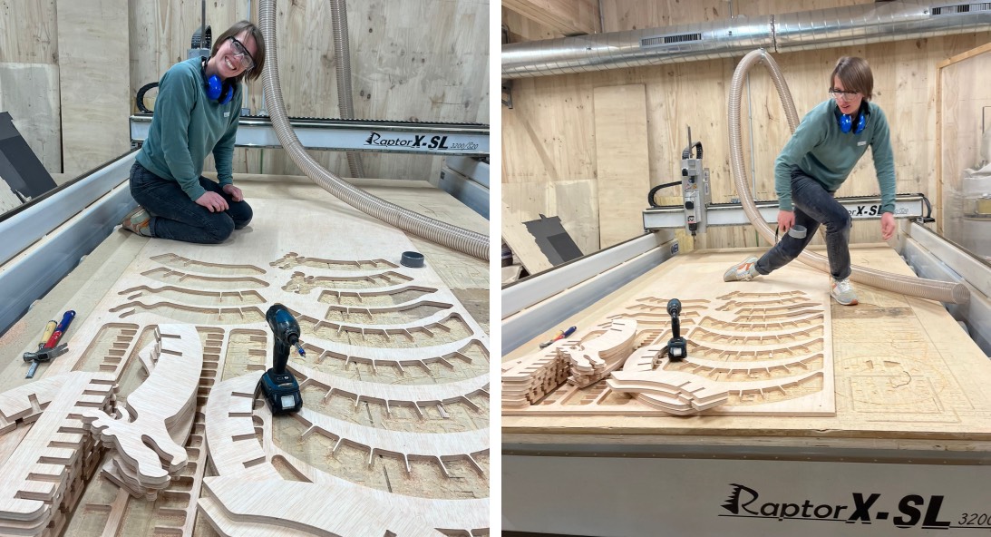
3. Assemble
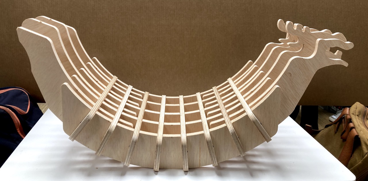
It actually took 4,5 hands to assemble the piece and I was happy for the looser tolerance of 5mm, but once it was assembled the pieces were a little bit loose and will need extra stabilization. Still it rocks and is stable enough for adults as well.
Once assembled in real life size, I realized one more design iteration would have been great. The side pieces would ideally stack from the top and not the bottom, which would require the 9-cut-plank to have up and downward cut slots.
Post processing
- sand the edges
- paint the different pieces
- gap the differences for final stability
Lessons Learned
- I would have been lost without the team on this assignment
- it's not only recommended that someone checks your file upfront of cutting, but really necessary to prevent errors
- RhinoCAM really needs a cheatsheet
- it was great to get into the workshop