
Week 13: Networking & Communication
This week is about I2C and serial communication, so I wanted to conduct a basic test where I would connect my custom designed board to the Barduino to send and recieve messages via WiFi and also through pins. This is the group assignment for the week!
Serial communication is a communication technique used in telecommunications wherein data transfer occurs by transmitting data one bit at a time in a sequential order over a computer bus or a communication channel. It is the simplest form of communication between a sender and a receiver. Because of the synchronization difficulties involved in parallel communication, along with cable cost, serial communication is considered best for long-distance communication.
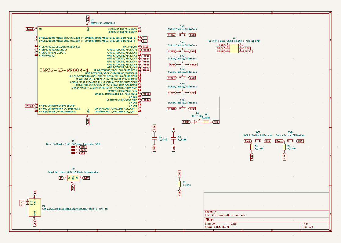
This is the schematic for my board, which was designed and mainly functions as a MIDI controller:
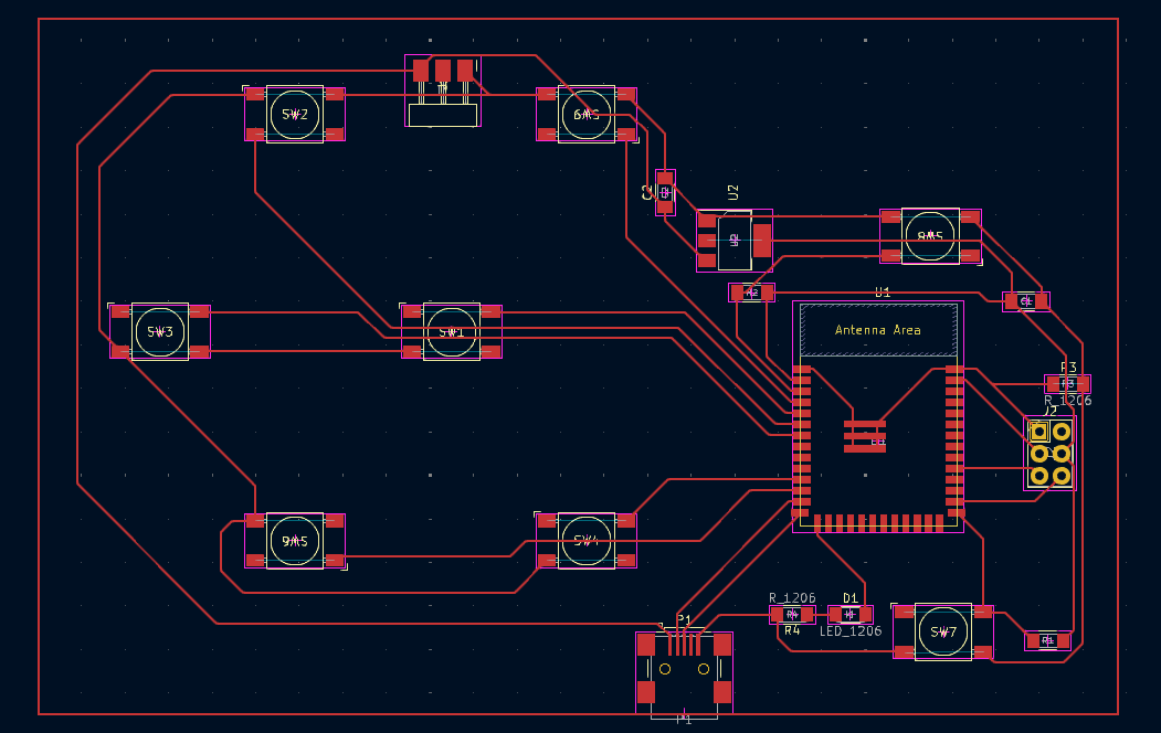
And this is my board design:
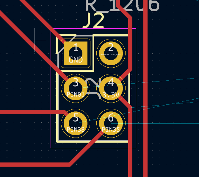
Both my MIDI board and the Barduino board, which was designed in Fab Lab Barcelona and handed out to each member of the cohort, use an ESP32S3 MCU, which is equipped with WiFi. For serial communication, I connected two of the pins from the conheader pins on my MIDI board to two of the Barduino pins via female to female cables.
Detail of the connheader pins from my MIDI board that I used to connect with the Barduino:
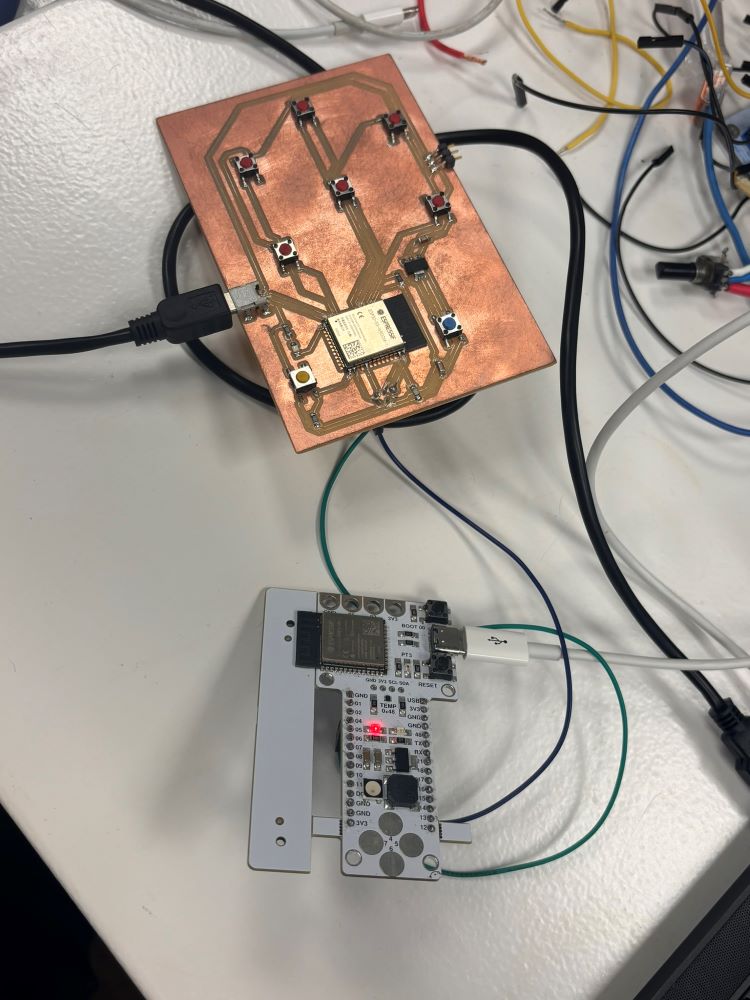
Board to board setup:
This is the base code for my the sketches I used for establishing serial communication:
//Transmitting Arduino //Potentiometer connected to A0, +5V, GND- provides one test value //Pin 12 Arduino One Connected to Pin 13 Arduino Two //Pin 13 Arduino One Connected to Pin 12 Arduino Two //Arduino Grounds connected together #includeSOURCE: https://designbuildcode.weebly.com/software-serial-two-arduinos.html//Use software serial so as not to conflict with serial download and monitor SoftwareSerial mySerial(12,13); // RX, TX int testvalue = 200; void setup() { mySerial.begin(9600); } void loop() { mySerial.print(analogRead(A0)); mySerial.print( " "); mySerial.println( testvalue); delay(200); } //Receiving Arduino #include //using software serial so as not to conflict with serial download SoftwareSerial mySerial(12,13); // RX, TX int potpinValue = 0; int testvalue = 0; void setup() { mySerial.begin(9600); //setup software serial Serial.begin(9600); //setup serial monitor } void loop() { while (mySerial.available() == 0) { } testvalue = mySerial.parseInt(); potpinValue =mySerial.parseInt(); //print received values to serial monitor Serial.print(testvalue); Serial.print(" "); // print tab for readability Serial.println(potpinValue); delay(100); }
After understanding the basics of how to connect one board to another using the Arduino IDE, the next step was to create a transmitting sketch and a recieving sketch to establish communication.
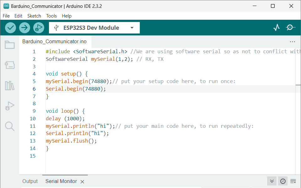
#include//We are using software serial so as not to conflict with serial download and monitor. SoftwareSerial mySerial(1,2); // RX, TX void setup() { mySerial.begin(74880);// put your setup code here, to run once: Serial.begin(74880); } void loop() { delay (1000); mySerial.println("hi");// put your main code here, to run repeatedly: Serial.println("hi"); mySerial.flush(); }
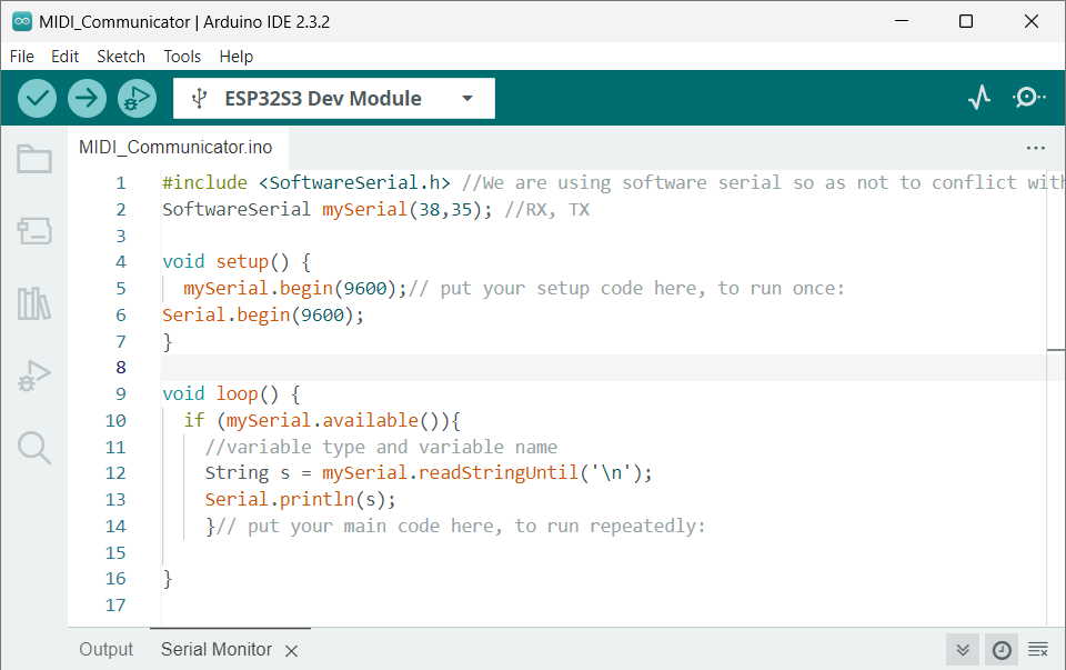
#include//We are using software serial so as not to conflict with serial download and monitor SoftwareSerial mySerial(38,35); //RX, TX void setup() { mySerial.begin(74880);// put your setup code here, to run once: Serial.begin(74880); } void loop() { if (mySerial.available()){ //variable type and variable name String s = mySerial.readStringUntil('\n'); Serial.println(s); }// put your main code here, to run repeatedly: }
Here's the summary of the codes:
- 1. Includes the SoftwareSerial library to enable serial communication on non-standard pins.
- 2. Defines a software serial port using digital pins.
- 3. In the setup() function:
- Initializes both the software serial port and the hardware serial port with a baud rate of 74880. - 4. In the loop() function:
-Check if data is available on the software serial port (mySerial).
-If data is available, read the incoming string until a newline character ('\n') is encountered.
- Delays for 1 second.
- Sends the string "hi" through both the software serial and hardware serial ports.
-Print the received string to the hardware serial port (Serial), which typically displays the output in the serial monitor.
- Waits for the software serial transmission to complete.
This code allows for simultaneous communication via hardware and software serial ports without conflicts, especially useful when debugging or interacting with multiple serial devices.
Issues
I had trouble establishing communication at different points, which is also why the code is simple - to begin with the basic and build up. This took a while to work on my computer, even if the code is quite straightforward.
One takeaway is that, sometimes, having the serial monitor open on the IDE can sometimes interfere with the outputting on the serial monitor since it keeps the connection too busy to upload the code. I made sure that I closed the serial monitor when uploading new code onto my board.
Make sure the USB mode is set to Hardware CDC JTAG.
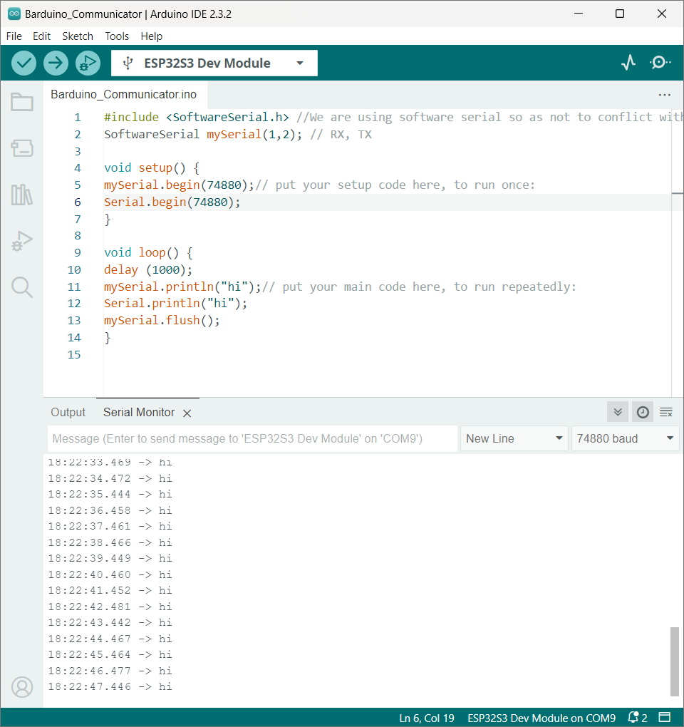
The quality of the physical connection/cables are obviously important. The communication changed for the better when working with 9600 baud rate when I pressed down the cables into the connheader pins, for example.
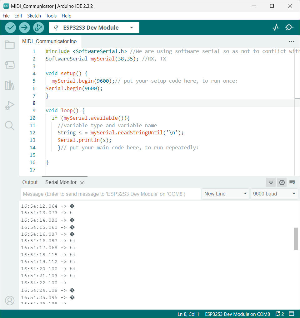
At first, I used 9600 baud rate, which gave me readings that were inconsistent and off:
A baud rate increase from 9600 to 57600 worked well and made the connection smoother and the lines consistent:
I2C Communication
I wanted to establish communication from one ESP board to the other using ESP NOW. The Barduino has capacitive touch pads on pins 4, 5, 6 and 7 and I wanted to send the message to my MIDI Controller board when the CTP were interrupted.
The second board has a tactile switch on pin 4 and I wanted to send a message to the Barduino by interacting with the switch.
To send messages between each board, we need to know their MAC address first. Each board has a unique MAC address. Upload the following code to each of your boards to get their MAC address.
        #include
        #include

        void readMacAddress(){
          uint8_t baseMac[6];
          esp_err_t ret = esp_wifi_get_mac(WIFI_IF_STA, baseMac);
          if (ret == ESP_OK) {
            Serial.printf("%02x:%02x:%02x:%02x:%02x:%02x\n",
                          baseMac[0], baseMac[1], baseMac[2],
                          baseMac[3], baseMac[4], baseMac[5]);
          } else {
            Serial.println("Failed to read MAC address");
          }
        }

        void setup(){
          Serial.begin(115200);

          WiFi.mode(WIFI_STA);
          WiFi.STA.begin();

          Serial.print("[DEFAULT] ESP32 Board MAC Address: ");
          readMacAddress();
        }

        void loop(){

        }
Source: Rui Santos & Sara Santos - Random Nerd Tutorials
You can find the complete project details at Random Nerd Tutorials
Once you've uplaoded this code on both boards, the serial monitor will display each board's MAC address:
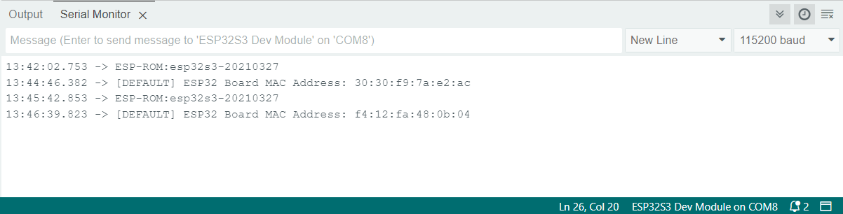
This is the address for the board with capacitive touch is: ESP32 Board MAC Address: 30:30:f9:7a:e2:ac.
This is the address for the board with the tactile switch: ESP32 Board MAC Address: f4:12:fa:48:0b:04.
Now that MAC addresses are established, we can go ahead and run a code for each board to send messages to each other.
To establish communication between two ESP32S3 boards, you can use ESP-NOW, a connectionless communication protocol developed by Espressif. It allows multiple devices to communicate with one another without needing a Wi-Fi network.
Hardware Setup
Board 1 (with capacitive touch pads): Touch pads connected to GPIOs 4, 5, 6, and 7.
Board 2 (with tactile switch): Tactile switch connected to GPIO 4.
Board 1 (Barduino)
          #include
          #include

          // MAC Address of Board 2
          uint8_t broadcastAddress[] = {0xF4, 0x12, 0xFA, 0x48, 0x0B, 0x04};

          typedef struct struct_message {
             char message[32];
           } struct_message;

          struct_message myData;

          void setup() {
            // Initialize Serial Monitor
             Serial.begin(115200);

            // Set device as a Wi-Fi Station
            WiFi.mode(WIFI_STA);
            Serial.println("ESP32 Board MAC Address: ");
            Serial.println(WiFi.macAddress());

            // Init ESP-NOW
            if (esp_now_init() != ESP_OK) {
                Serial.println("Error initializing ESP-NOW");
                return;
             }

            // Register peer
             esp_now_peer_info_t peerInfo;
             memcpy(peerInfo.peer_addr, broadcastAddress, 6);
             peerInfo.channel = 0;
             peerInfo.encrypt = false;

            if (esp_now_add_peer(&peerInfo) != ESP_OK) {
                Serial.println("Failed to add peer");
                return;
            }

            // Attach interrupt to touch pads
            touchAttachInterrupt(T4, sendMessage, 40);
            touchAttachInterrupt(T5, sendMessage, 40);
            touchAttachInterrupt(T6, sendMessage, 40);
            touchAttachInterrupt(T7, sendMessage, 40);
        }

        void sendMessage() {
            strcpy(myData.message, "Touch Detected!");
            esp_err_t result = esp_now_send(broadcastAddress, (uint8_t *) &myData, sizeof(myData));

            if (result == ESP_OK) {
                Serial.println("Sent with success");
            } else {
                Serial.println("Error sending the data");
            }
        }

            void loop() {
                // Main loop does nothing, waiting for touch interrupts
            }
Board 2 (MIDI Controller)
        #include
        #include

        // MAC Address of Board 1
        uint8_t broadcastAddress[] = {0x30, 0x30, 0xF9, 0x7A, 0xE2, 0xAC};

        typedef struct struct_message {
            char message[32];
        } struct_message;

        struct_message myData;

        void setup() {
            // Initialize Serial Monitor
            Serial.begin(115200);

            // Set device as a Wi-Fi Station
            WiFi.mode(WIFI_STA);
            Serial.println("ESP32 Board MAC Address: ");
            Serial.println(WiFi.macAddress());

            // Init ESP-NOW
            if (esp_now_init() != ESP_OK) {
                Serial.println("Error initializing ESP-NOW");
                return;
            }

            // Register peer
            esp_now_peer_info_t peerInfo;
            memcpy(peerInfo.peer_addr, broadcastAddress, 6);
            peerInfo.channel = 0;
            peerInfo.encrypt = false;

            if (esp_now_add_peer(&peerInfo) != ESP_OK) {
                Serial.println("Failed to add peer");
                return;
            }

            // Initialize button
            pinMode(4, INPUT_PULLUP);
        }

        void loop() {
            if (digitalRead(4) == LOW) {
                strcpy(myData.message, "Button Pressed!");
                esp_err_t result = esp_now_send(broadcastAddress, (uint8_t *) &myData, sizeof(myData));

                if (result == ESP_OK) {
                    Serial.println("Sent with success");
                } else {
                    Serial.println("Error sending the data");
                }

                // Debounce
                delay(1000);
            }
        }
Board 1 Setup
- Initializes ESP-NOW and sets the device as a Wi-Fi station.
- Registers Board 2 as a peer using its MAC address.
- Configures touch interrupts on the specified GPIOs to send a message when a touch is detected.
Board 2 Setup
- Initializes ESP-NOW and sets the device as a Wi-Fi station.
- Registers Board 1 as a peer using its MAC address.
- Checks the status of the tactile switch and sends a message when the switch is pressed.
ESP-NOW Initialization: Both boards must initialize ESP-NOW and register each other's MAC addresses.
Interrupt Handling: Board 1 uses touch interrupts to detect touch events and send messages. Board 2 checks the button status in the loop and sends messages when the button is pressed.
Debouncing: A delay is added after sending a message on Board 2 to debounce the button press.
Upload the respective codes to the two ESP32S3 boards and test the communication. When you touch the capacitive pads on Board 1, it should send a message to Board 2. Similarly, pressing the tactile switch on Board 2 should send a message to Board 1.