
Week 11: Input Devices
Here is the group assignment link for this week!
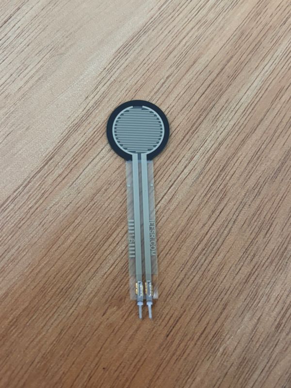
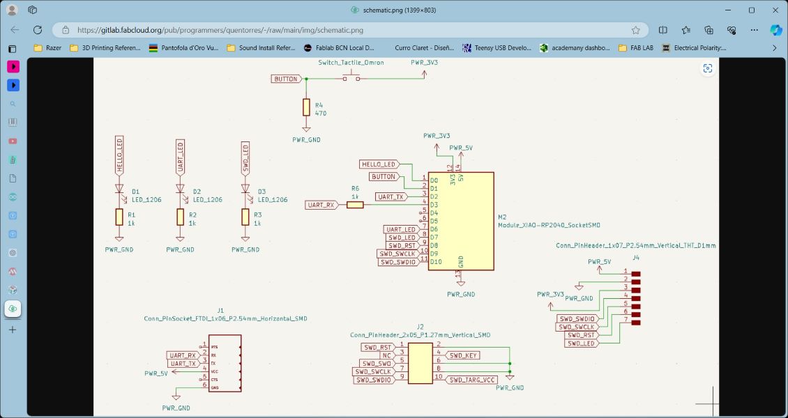
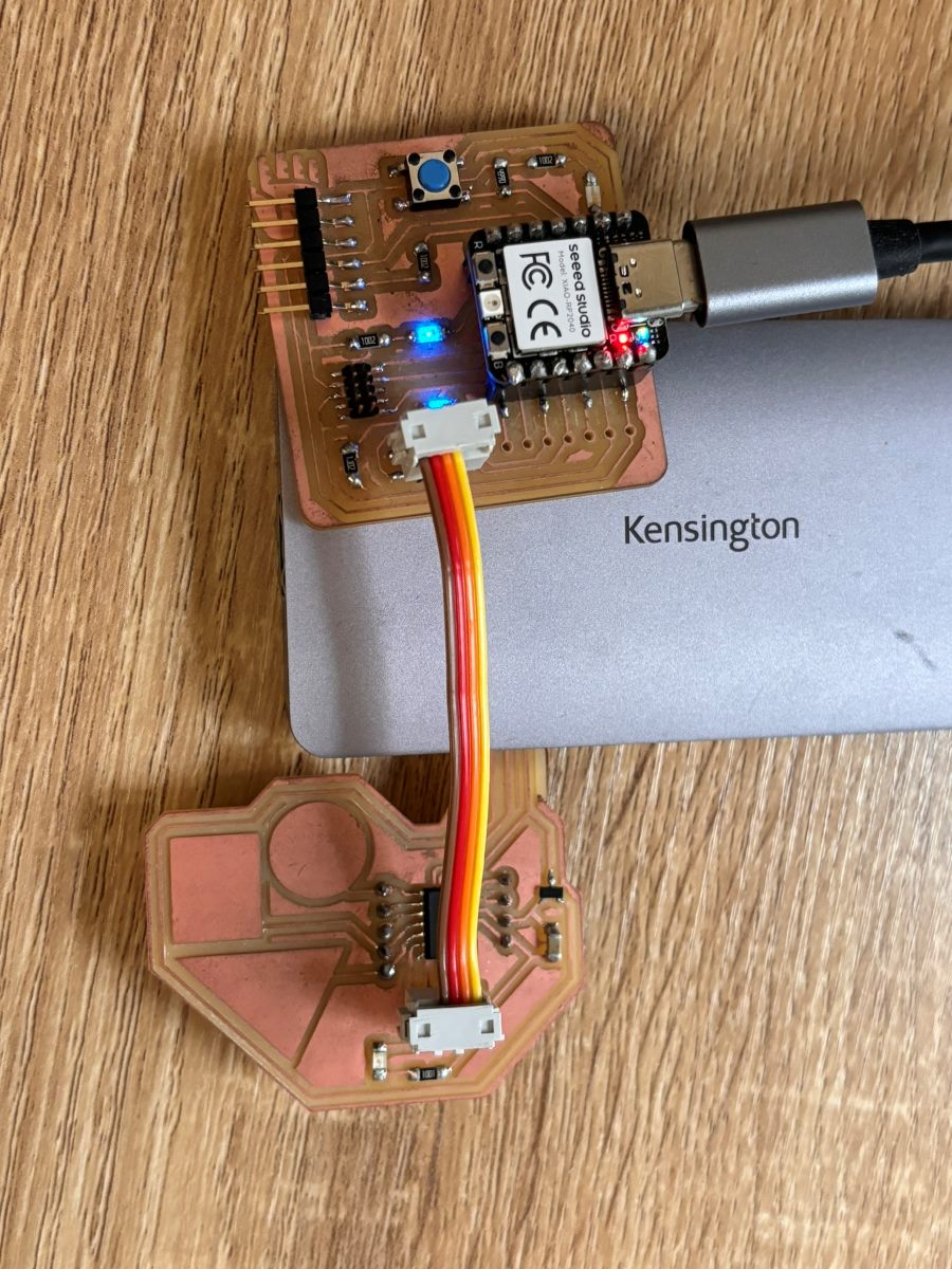
This week, we learned about input devices and how to implement them into our workflow. Input devices are hardware components used to provide data and control signals to an information processing system, such as a computer or microcontroller. I chose to work with a force sensing resistor since I'm interested in touch related sensors of all sorts. For this assignment, my goal was to get a sensor reading on my PCB equiped with a SAMD11 MCU.
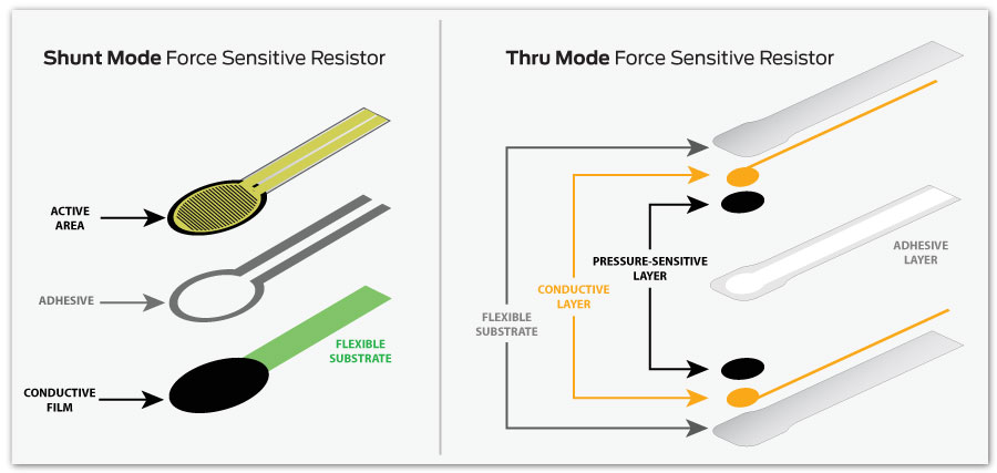
An FSR stands for Force Sensing Resistor, which is a sensort that changes its resistance depending on the amount of pressure, force or stress applied to it. They are simple to use and low cost. Force sensing resistors are a piezoresistive sensing technology. This means they are passive elements that function as a variable resistor in an electrical circuit.
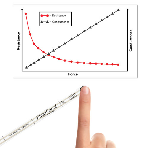
As shown in Figure 1, when unloaded, the sensor has a high resistance (on the order of Megaohms (MΩ)) that drops as force is applied (usually on the order of Kiloohms (KΩ)). When you consider the inverse of resistance (conductance), the conductance response as a function of force is linear within the sensor’s designated force range.
Workflow
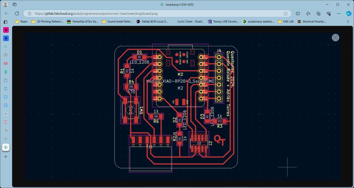
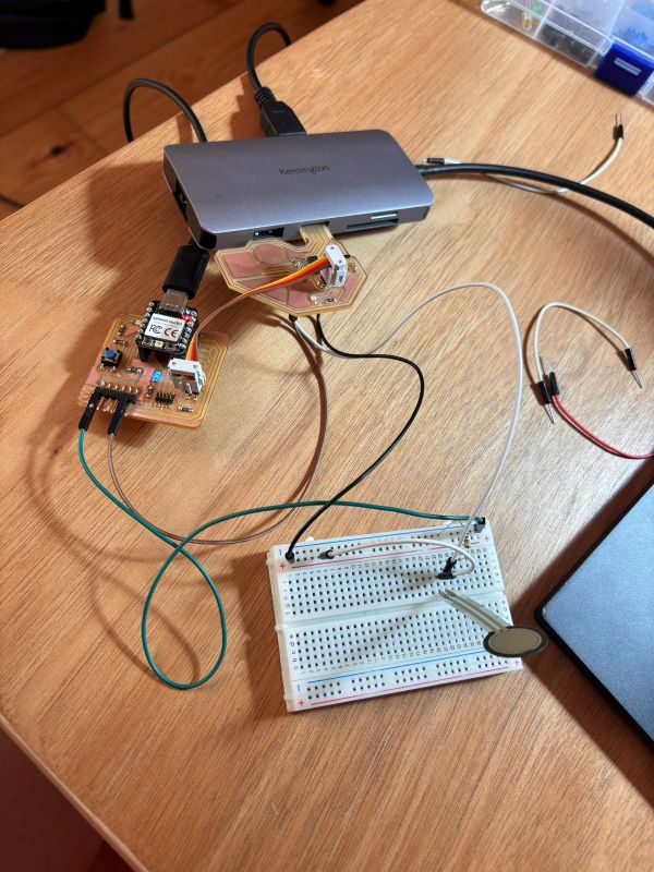
I started off by using my Quentorres board as a programmer to flash the SAMD11 MCU. I was able to program the SAMD11 both with and without the Quentorres board, but kept running into a communication issue and was unable to get serial communication between my PCB and the computer.
To troubleshoot, with the help of Daniel Mateos, I attempted to connect the TX pin PA09 on the SAMD11 to the RX on the Quentorres to no results. We then attempted to initiate a second serial connection (Serial1...), scanning the pins with a multimeter to detect any signals, but they all turned up at 0V.
An additional attempt was made to test default connection versus Serial 1 as alternative communication method.
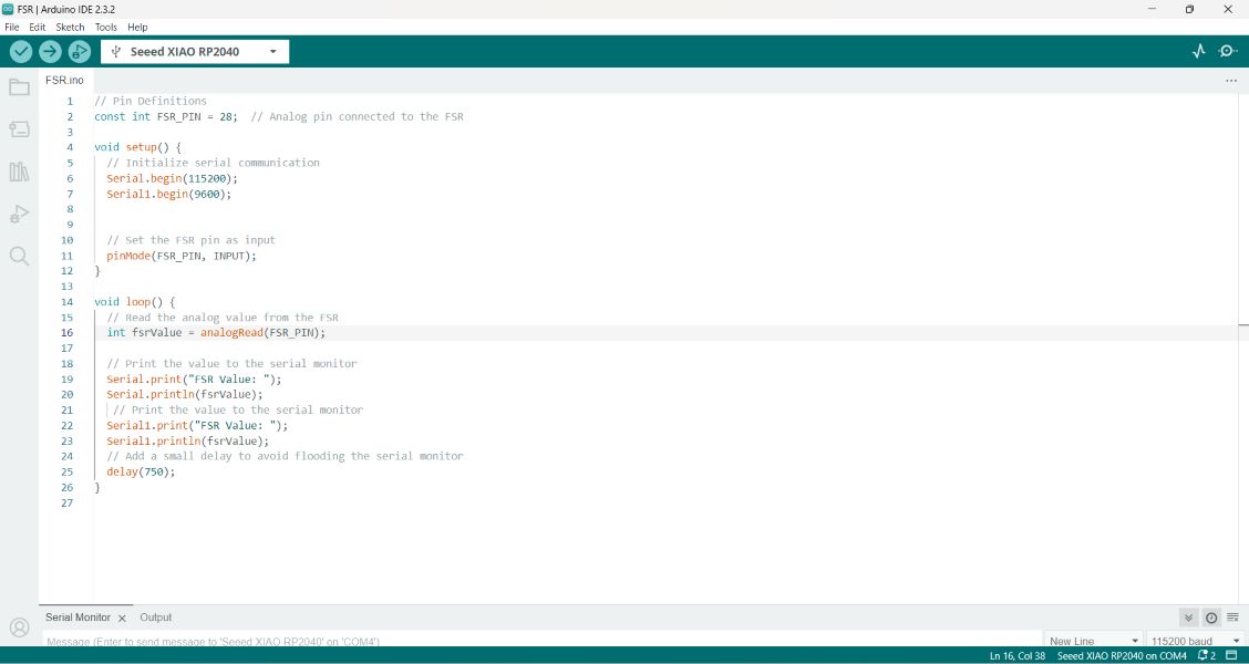
Here is the code to get a reading on the FSR:
      const int FSR_PIN = 28;  // Analog pin connected to the FSR

      void setup() {
        // Initialize serial communication
        Serial.begin(115200);
        Serial1.begin(9600);


        // Set the FSR pin as input
        pinMode(FSR_PIN, INPUT);
      }

      void loop() {
        // Read the analog value from the FSR
        int fsrValue = analogRead(FSR_PIN);

        // Print the value to the serial monitor
        Serial.print("FSR Value: ");
        Serial.println(fsrValue);
         // Print the value to the serial monitor
        Serial1.print("FSR Value: ");
        Serial1.println(fsrValue);
        // Add a small delay to avoid flooding the serial monitor
        delay(750);
      }
Takeaways
We observed that the LED on the Quentorres was flashing throughout, changing with edits in the sketch (delay value), meaning the Quentorres was the board being programmed instead.
Knowing that, I wanted to still test the FSR on a board, so went ahead and used the Quentorres to get a reading anyway because I didn't want to stop at my board and a problem that requires more experience to resolve.
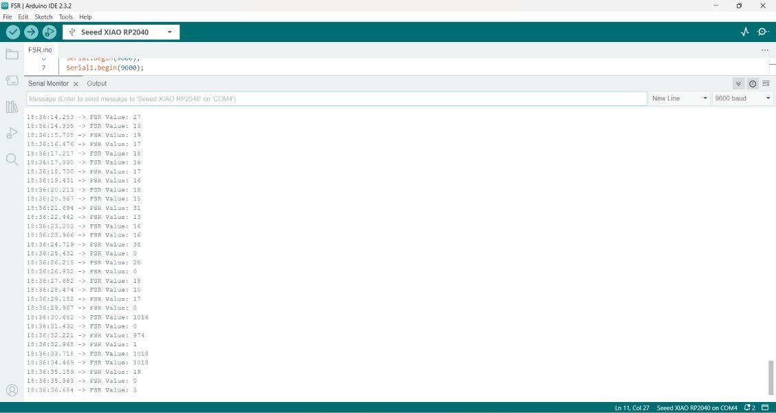
As shown in the screengrab, the serial monitor was printing values according to my interaction with the FSR.
Blinking an LED with SAMD11 Board
This was my capacitive touch test I performed with my SAMD 11 equipped board. I want to mention some takeaways first, based on specific challenges that I've been encountering: my PCB board connectivity isn't always as reliable and I have had to troubleshoot quite a bit to address this issue.
It's been a good learning tool to run into this issue due to the considerations to keep in mind when designing and milling a board and then soldering components onto it. It's also time consuming to use a board that doesn't connect easily to a port/computer, but figuring out what works when a board isn't responding is a valuable spot to be in regardless.
Here are a couple of learnings as a note to self and hopefully others:
- Make sure your custom PCB, if using a plain USB port, doesn't have conductive material surrounding your USB port. I know this is an obvious thing but, starting out in electronics, it wasn't immediately apparent to me as something that causes issues. I had to physically remove a layer of copper coating and I now know to address this issue in Inkscape or whatever program used to setup your image file!
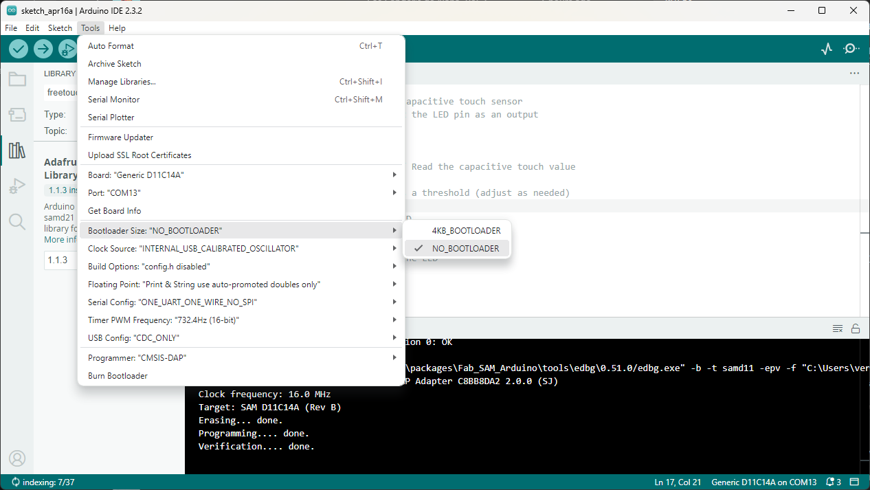
- If my board isn't working for me to perform a simple code (I chose the SAMD11), I burn bootloader. If I want to run a program that takes up more memory, I select "No bootloader" and program via the port where my programming board is active.
Using the same board I printed and worked with previously, the idea was to make use of the touch capacitance built into the board itself. Since I have been following Quentin Bolsee's lead.
My capacitive touch pads correspond to these pins:
- pin 05
- pin 14
- pin 15
At first, I needed to make the LED on PIN 31 blink in accordance to a specified reading threshold. The code, which includes the open source Adafruit Library, is as follows:
#include// Create capacitive touch objects for pins 5, 14, and 15 Adafruit_FreeTouch qt5(5, OVERSAMPLE_4, RESISTOR_50K, FREQ_MODE_NONE); Adafruit_FreeTouch qt14(14, OVERSAMPLE_4, RESISTOR_50K, FREQ_MODE_NONE); Adafruit_FreeTouch qt15(15, OVERSAMPLE_4, RESISTOR_50K, FREQ_MODE_NONE); const int ledPin = 31; // Pin for the LED void setup() { // Initialize the capacitive touch sensors qt5.begin(); qt14.begin(); qt15.begin(); pinMode(ledPin, OUTPUT); // Set the LED pin as an output } void loop() { // Read the capacitive touch values for each pin int qt_value5 = qt5.measure(); int qt_value14 = qt14.measure(); int qt_value15 = qt15.measure(); // Check if any touch value exceeds a threshold (adjust as needed) if (qt_value5 > 550 || qt_value14 > 550 || qt_value15 > 550) { // If touched, turn on the LED digitalWrite(ledPin, HIGH); } else { // If not touched, turn off the LED digitalWrite(ledPin, LOW); } }
In this modified code:
Running this code was unsuccessful for me. I tried different things, but as I am not well versed in programming and working with the Arduino IDE yet, I couldn't figure out what the source of the issue was.
Following Andrea Rubio's documentation after not getting any touch capacitance results, I attempted to download the 1.1.2 version of the Adafruit Library to see if it gave me any results. I did this because apparently, there's an issue with trying to run this code on the latest version.
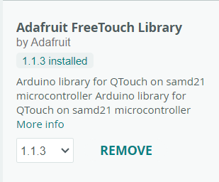
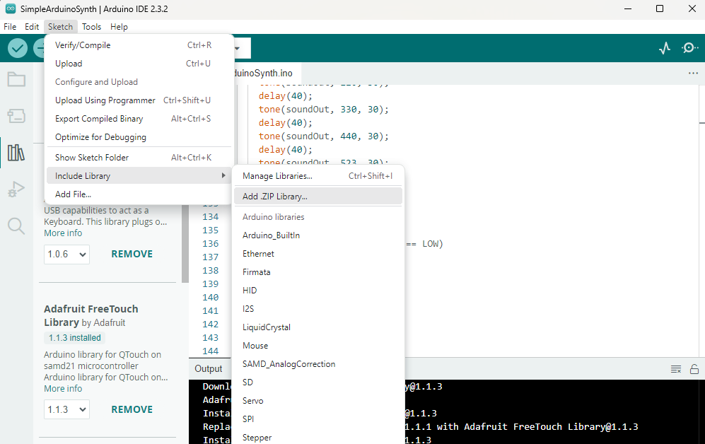
While adding the library as a .zip file seemed to work smoothly, and after multiple restarts to the Arduino IDE program after doing so, the 1.1.2 version was not showing up as an option. The versions available jumped from 1.1.1 to 1.1.3.
As much as I tried to implement the 1.1.2 version, which seemed to work for my peeer, I was unsuccessful. I had to use another method to get the touch capacitance to work, so I defaulted on this code, thanks toChristine Grupel's solution, which is documented on her page.
            #define PIN 5
            #define PIN2 14
            #define PIN3 15
            #define LED 31

            void setup () {

              Serial.begin(115200);
              pinMode(PIN, INPUT_PULLUP);
              pinMode(PIN2, INPUT_PULLUP);
              pinMode(PIN3, INPUT_PULLUP);

              pinMode(LED, OUTPUT);

            }

            void loop(){
              Serial.print ("PIN=");
              Serial.print(analogRead(PIN));
              Serial.print ("PIN2=");
              Serial.print(analogRead(PIN2));
              Serial.print ("PIN3=");
              Serial.println(analogRead(PIN3));

              if (analogRead(PIN) >= 800 || analogRead(PIN2) >= 500 || analogRead(PIN3) >= 800) {
                digitalWrite(LED, HIGH);
              }
              else {
                digitalWrite(LED, LOW);
              }
              delay(200);

            }
This offered some results, however, PIN 14 proved unresponsive while the program was running, so it gives me something to troubleshoot and figure out in the coming days. I had determined earlier on that the power provided by the USB port is enough, based on any troubleshooting I did with advisors and my instructors, but that is also an important factor to keep in mind. I'm not saying that it affects my non-working pad, but just as a general detail to keep in mind...