
Week 9: Output Devices
Here is the group assignment link for this week!
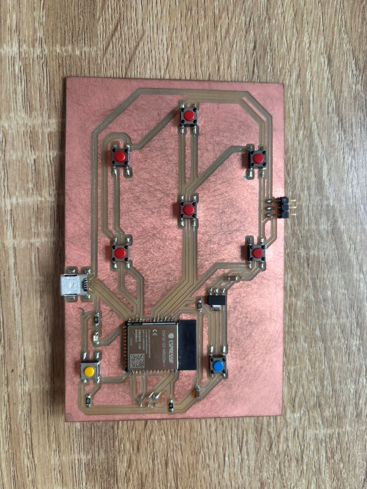
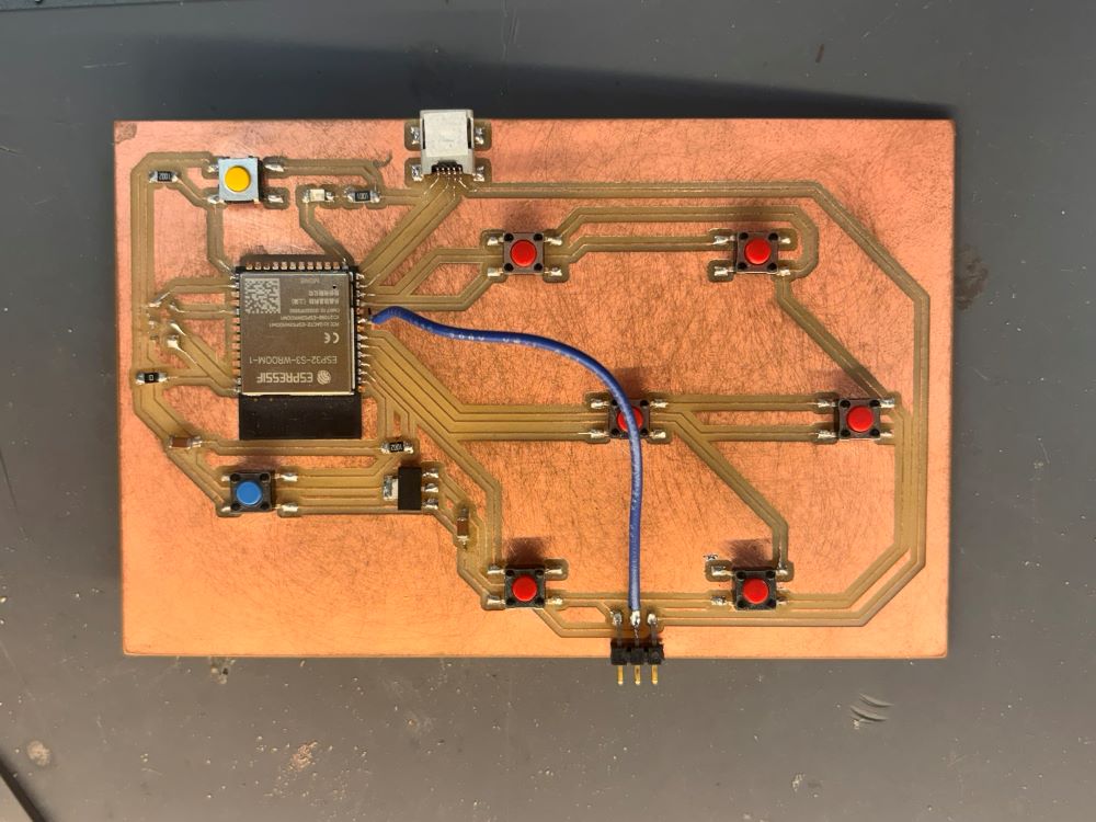
This week we learned about output devices and how to apply them to the baords we are making ourselves. I used my board to interact with a neopixel ring, however, I realized I had to adapt the circuit with a jumper wire to connect the Data pad of the 3 x Pin header SMD because I forgot to connect this to a pin on my ESP S3 32 WROOM ! Classic mistake. Here is the ammended circuit board:
Uploading the Code
I connected my circuit baord on the Arduino IDE, selected "ESP S3 32 Dev Module" from the bord + port drop-down list. Make sure that the following settings in the Tools menu are selected:
- Download Adafruit Neopixel Library
- USB CDC on Boot: Enabled
- USB Mode: USB OTG
This code is designed to control a NeoPixel ring using an Arduino. It allows the user to adjust the color of the NeoPixel ring by pressing various buttons connected to the Arduino.
          #include

            // Which pin on the Arduino is connected to the NeoPixels?
            #define PIN        16 // On Trinket or Gemma, suggest changing this to 1

            // How many NeoPixels are attached to the Arduino?
            #define NUMPIXELS 7 // Popular NeoPixel ring size

            Adafruit_NeoPixel ring(NUMPIXELS, PIN, NEO_GRB + NEO_KHZ800);

            int R;
            int G;
            int B;

            void setup() {
              ring.begin(); // INITIALIZE NeoPixel strip object (REQUIRED)
              pinMode(4, INPUT_PULLUP);
              pinMode(5, INPUT_PULLUP);
              pinMode(6, INPUT_PULLUP);
              pinMode(18, INPUT_PULLUP);
              pinMode(7, INPUT_PULLUP);
              pinMode(8, INPUT_PULLUP);
              pinMode(0, INPUT_PULLUP);
            }

            void loop() {
              if (digitalRead(4) == 0){
                R = R + 1;
                if(R>255){
                  R = 255;
                }
              }
              if (digitalRead(5) == 0){
                G = G + 1;
                if(G>255){
                  G = 255;
                }
              }
              if (digitalRead(6) == 0){
                B = B + 1;
                if(B>255){
                  B = 255;
                }
              }
              if (digitalRead(18) == 0){
                R = R - 1;
                if(R < 0){
                  R = 0;
                }
              }
              if (digitalRead(8) == 0){
                G = G - 1;
                if(G < 0){
                  G = 0;
                }
              }
              if (digitalRead(7) == 0){
                B = B - 1;
                if(B < 0){
                  B = 0;
                }
              }
              if (digitalRead(0) == 0){
                R = 0;
                G = 0;
                B = 0;
              }
              ring.fill(ring.Color(R, G, B), 0, 7);
              ring.show();
              delay(100);
            }
Code Explanation
Adafruit_NeoPixel ring(NUMPIXELS, PIN, NEO_GRB + NEO_KHZ800);
This line creates a ring object of type Adafruit_NeoPixel with the specified number of pixels, pin number, and LED type configuration (NEO_GRB with 800 KHz signal).
          int R;
          int G;
          int B;
These lines declare integer variables R, G, and B to store the red, green, and blue color values, respectively.
        void setup() {
          ring.begin(); // INITIALIZE NeoPixel strip object (REQUIRED)
          pinMode(4, INPUT_PULLUP);
          pinMode(5, INPUT_PULLUP);
          pinMode(6, INPUT_PULLUP);
          pinMode(18, INPUT_PULLUP);
          pinMode(7, INPUT_PULLUP);
          pinMode(8, INPUT_PULLUP);
          pinMode(0, INPUT_PULLUP);
        }
The setup function initializes the NeoPixel ring and configures pins 4, 5, 6, 18, 7, 8, and 0 as input pins with internal pull-up resistors.
The loop function runs continuously, performing the following tasks:
- Read Button States: Each digitalRead checks if a button is pressed (button connected to pin reads LOW).
- Adjust color values: Increment or decrement the RGB values based on the button pressed and ensure the values remain within the range 0-255.
- Reset Colors: If the button connected to pin 0 is pressed, reset RGB values to 0.
- Update NeoPixel Ring: Use ring.fill and ring.show to set the color of all LEDs in the ring based on the RGB values.
- Delay: Add a 100ms delay to avoid rapid changes.
BIG THANKS to Josep Marti for helping me with this code.
Controlling a Virtual Piano with MIDI controller
The following is another exercise I did previosuly, using a custom MIDI controller and a virtual piano interfase as an output.
MIDI Board
This is the same controller I am using for my final project. It is a simple controller that is equipped with an ESP S3 32 and 7 tactile switches that are meant to set off sounds.
Uploading the Code
I connected my circuit baord and on the Arduino IDE, selected "ESP S3 32 Dev Module" from the bord + port drop-down list. Make sure that the following settings in the Tools menu are selected:
- USB CDC on Boot: Enabled
- USB Mode: USB OTG
After that was all set, I ran the following code:
#include "USB.h"
#include "USBMIDI.h"
USBMIDI MIDI;

const int pins[] = { 0, 4, 5, 6, 7, 8, 18 };
int butState[] = { 0, 0, 0, 0, 0, 0, 0 };
int prevState[] = { 0, 0, 0, 0, 0, 0, 0 };

int notes[] = { 24, 28, 31, 35, 38, 41, 45 }; //extended chord combination C E G B D F A


void setup() {
  MIDI.begin();
  USB.begin();
  for (int i = 0; i < 7; i++) {
    pinMode(pins[i], INPUT_PULLUP);
  }
  for (int i = 0; i < 7; i++) {
    butState[i] = digitalRead(pins[i]);
  }
  for (int i = 0; i < 7; i++) {
    prevState[i] = digitalRead(pins[i]);
  }
}

void loop() {
  for (int i = 0; i < 7; i++) {
    butState[i] = digitalRead(pins[i]);
    if (butState[i] != prevState[i]) {
      prevState[i] = butState[i];
      if (butState[i] == 1) {
        MIDI.noteOff(notes[i], 0);
      } else {
        MIDI.noteOn(notes[i], 126);
      }
    }
  }
  delay(100);
}
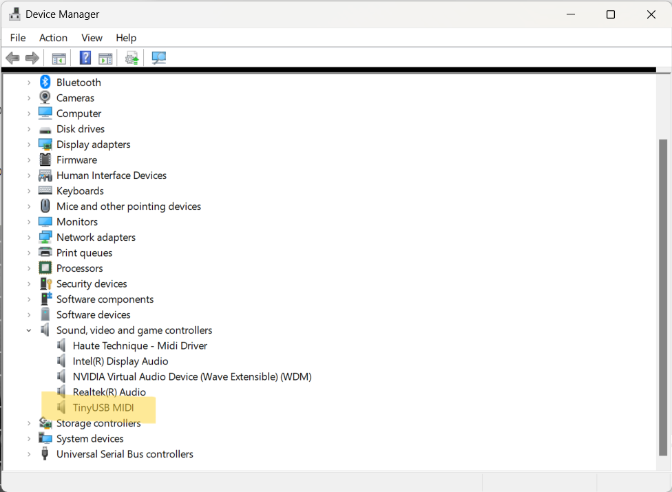
Once the code has been successfully uploaded, your computer should be able to read the circuit board as a MIDI device. It's good practice, or just something to check when in doubt, to open Device Manager and make sure your MIDI controller is being detected:
I then opened an internet browser and went to Virtual Piano to test out my MIDI controller. Here's how that worked out:
Virtual Piano is a small synthesizer / MIDI player library written for your Browser with GM like timbre map. All timbres are generated by the combinations of Oscillator and Dynamically generated BufferSource algolithmically without any PCM samples.