
Week 7: Computer Controlled Machining
CNC machines are automated milling devices that manufacture industrial components without direct human
assistance.
They use coded instructions sent to a computer, allowing factories to make parts accurately and quickly. CNC
machining is a "subtractive" manufacturing process that typically uses computerized controls and machine tools
to
remove layers of material from a blank (or workpiece) and produce a custom part. The automated nature of CNC
machining makes it possible to create simple, high-precision parts with high accuracy; and to fabricate unique,
medium-scale production series cost-effectively.
The CNC machining process begins with creating a 2D vector or 3D Computer-Aided Design (CAD) of a solid part.
Once
the CAD design is complete, the designer exports it to a CNC-compatible file format, such as STEP or IGES.
This week our task is to design, mill and assemble something BIG - preferrably something that doesn't need
fasteners or glue and also incorporates curved surfaces.
I took this week to begin the "skeleton" of my final project, which happened to change direction just before this week's assignment. Also, as I was designing and preparing my file for the CNC, the literal form of my final project changed as well.
Here's the link to our Group Assignment!
Design & Rhino Cam
I have been learning and using Fusion 360 throughout the course. I used it this week to design my piece and also incorporated a dogbone add-in that easily applies dogbones to files in preparation for milling. I then exported the sketch files to Rhino since we were using Rhino CAM to setup our designs for cutting.
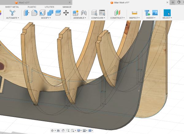
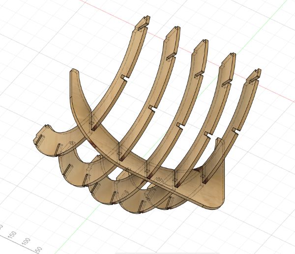
I started with sketching out the pieces to cut in Fusion 360. This week I attempted to make a spherical structure which could house a synthesizer:
My cut plan was to make more of a strictly spherical structure using horizontal and vertical "ribs":
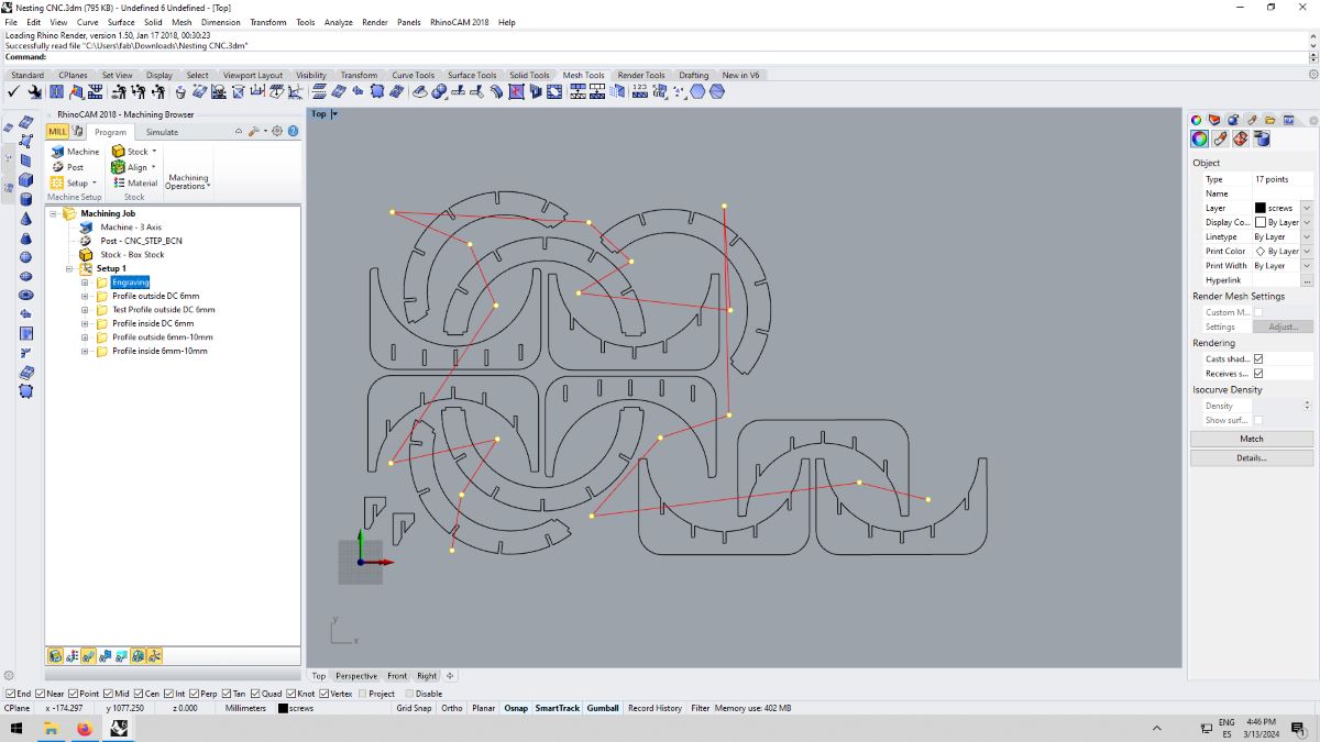
File Setup for Milling
We prepped files according to function/stages of the machining process. This means there is a logical workflow in which we machine, beginning with setting up a drill file to position the stock piece on the machine bed for fastening.
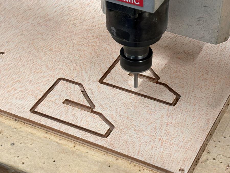
I used a 10mm thick plywood board and had the machine cut an initial pass with a down cut end mill 6mm
deep. I then switched that bit out for an up cut one to finish going through the board at 10mm depth.
I went with a downcut/upcut combination to avoid ripping the wood fibers too much and keep both
sides
of my pieces as clean as possible since they will be exposed in the final project. I also like avoiding wood
fillers (only my test pieces were all down cuts).
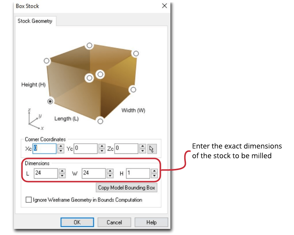
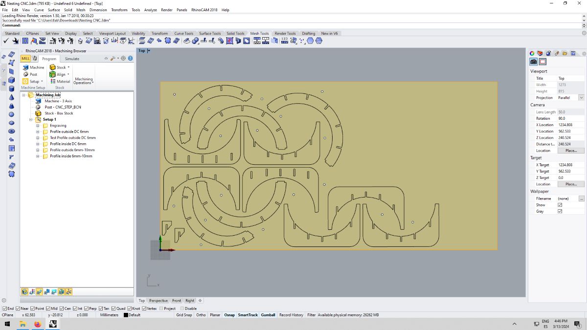
Stock
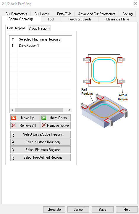
Select your cut stock and specify this in Rhino Cam in the stock geometry dialog box:
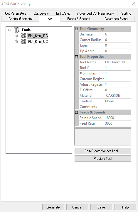
Select the endmill you will be using for cut and adjust settings according to mill. In our case, we used a 6mm flat down/up cut bit.
.jpg)
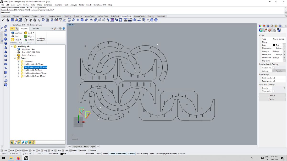
Drilling
Setting up the file for drilling the initial screw holes is important to fasten the piece onto the CNC bed. You establish this by adding points throughout the board between your cut pieces, making sure the drill holes are at an appropriate distance from the cut edge as to not interfere with the endmill.
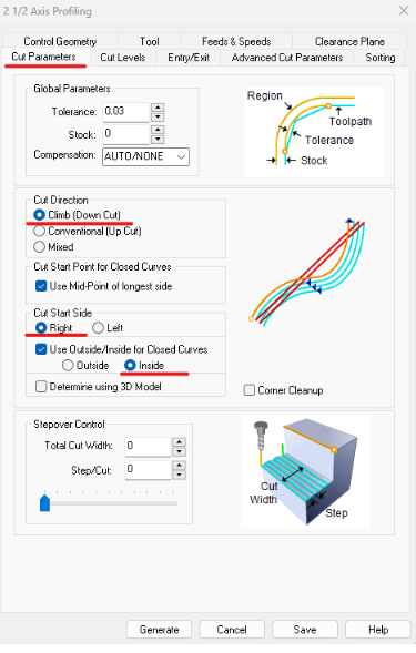
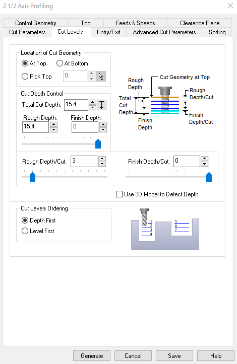
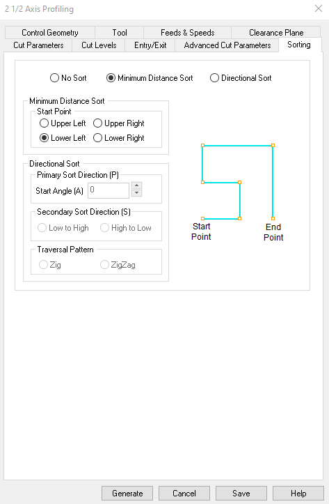
Down Cut/Up Cut
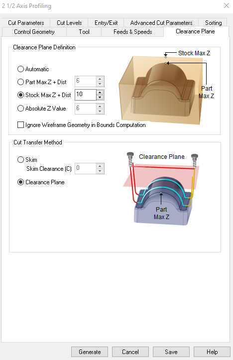
I set up my file for down cut at 6mm depth to cut a bit more than halfway through the piece and to reduce splintering caused by cutting the piece in one go.
Cut Direction: climb cut (down cut); Cut Start Side: Right; Use Outside/Inside for Closed Curves: Inside
Parameters
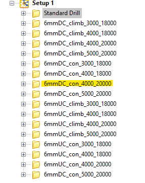
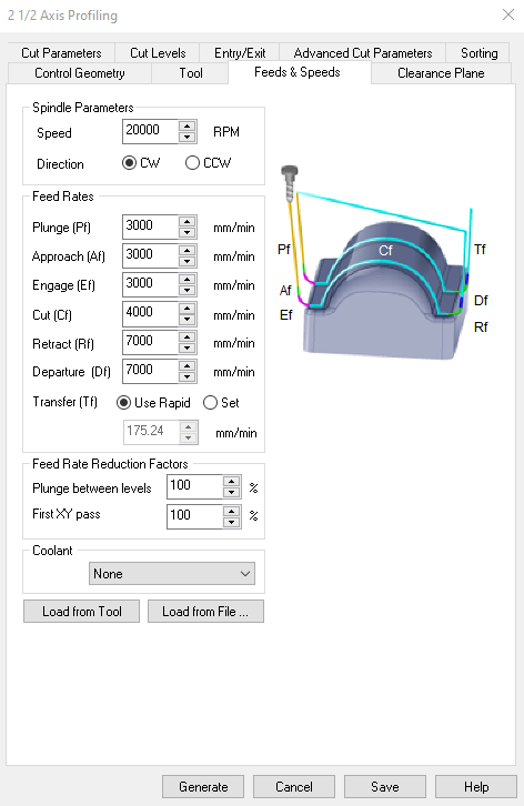
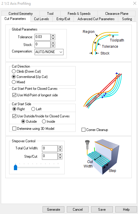
Parameter Settings:
Plunge: 2500, Approach: 2500, Engage: 2500
Cut: 4000, Retract: 4000, Departure: 4000
Speed: 200 000 RPMs (speed), a feedrate of 2500 and a cut depth of 6mm then 5mm.
Remember to add extra mm to the total cut depth to be sure to cut all the way through.
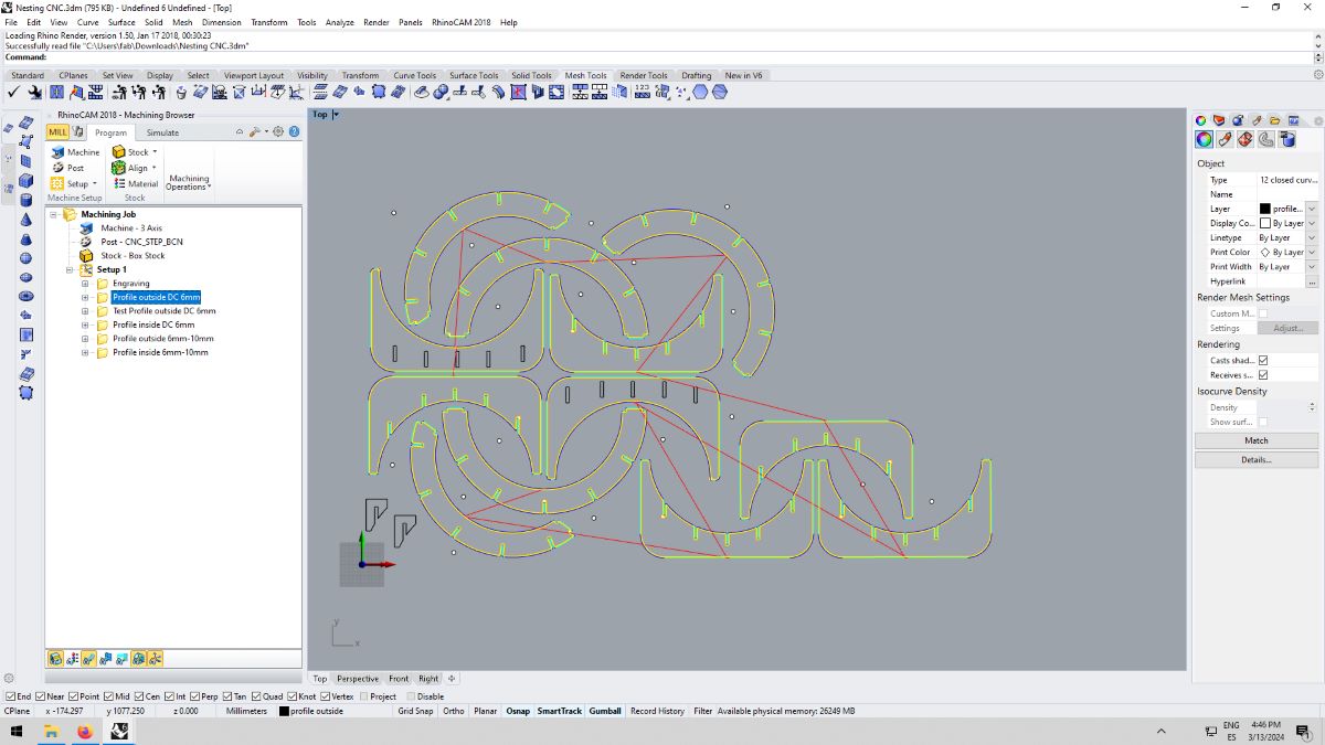
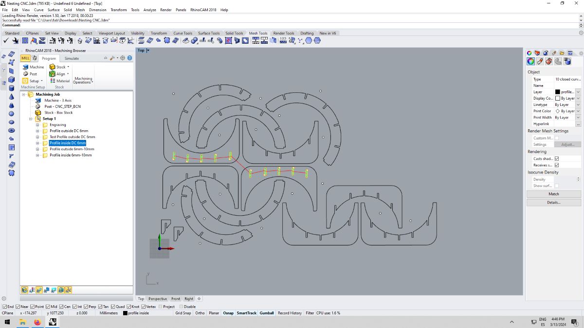
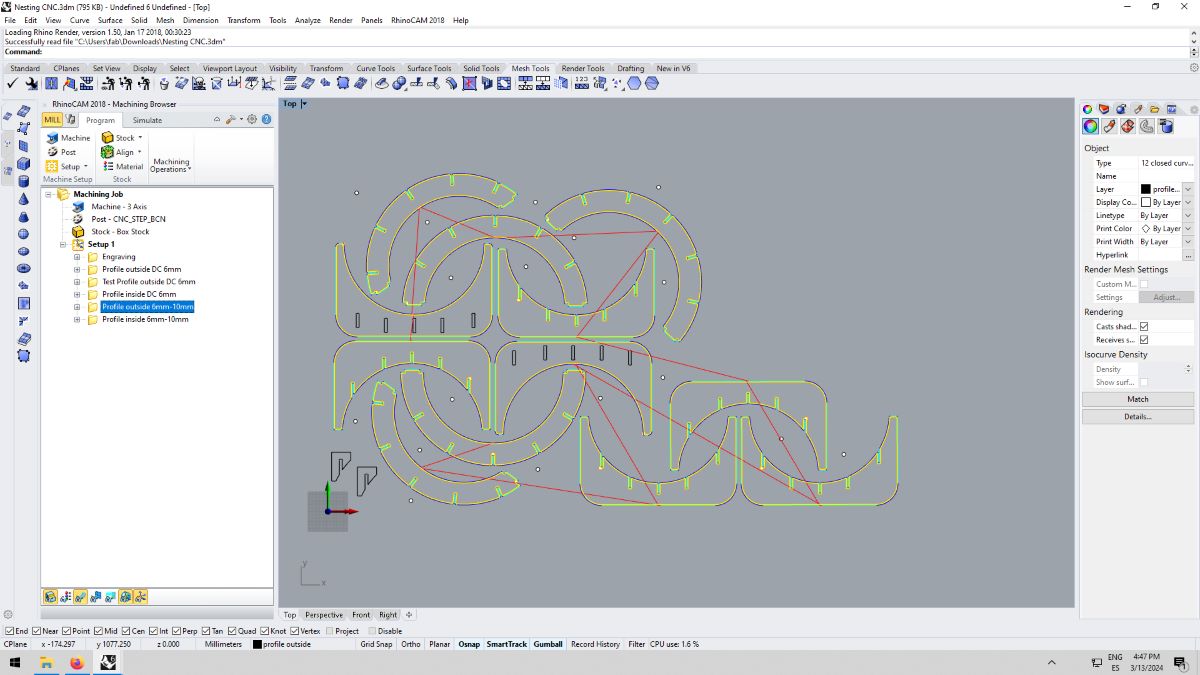

Profile inside down cut / Profile outer up cut
Workflow
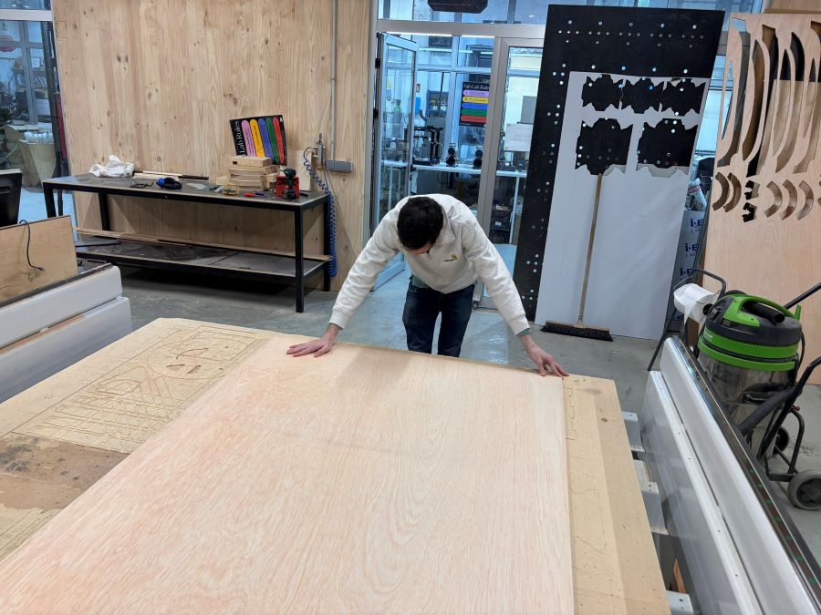
After the file was set, onto the Raptor! We used the Raptor X-SL 3200/S20 CNC milling machine, that is operated by the KinetiC-NC software.
- Align the plate in a 90 degree angle.
- Zero the X and Y by eyeballing the lower right corner and press 0 on the software.
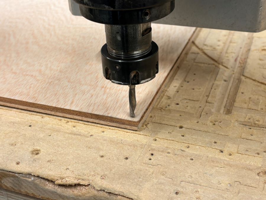
- Zero the Z by lowering the drill mill until approximately 5 cm to the plate.
- Move the remaining 5cm down with the remote control until the bit engraves a little bit into the plate and press 0 on the software.
Here's Josep adjusting the board referencing the edge on the sacrificial bed:
Zeroing the bit:
Test cut first:
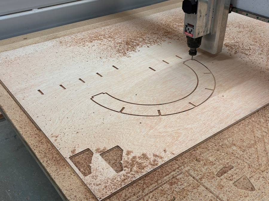
Milling the rest:
Here are the files:
Test File
Issues
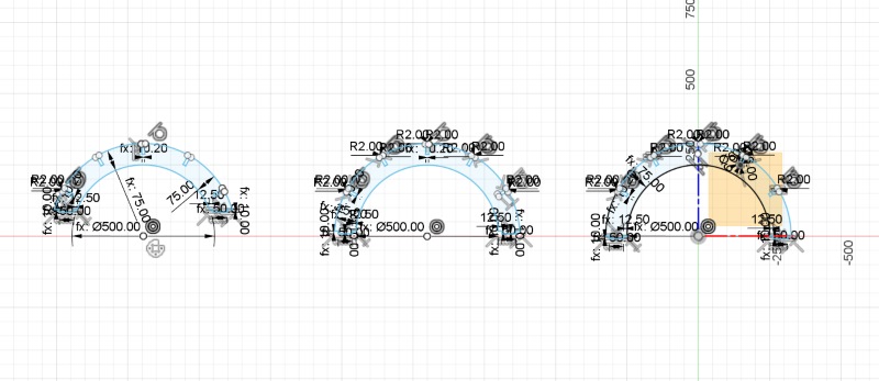
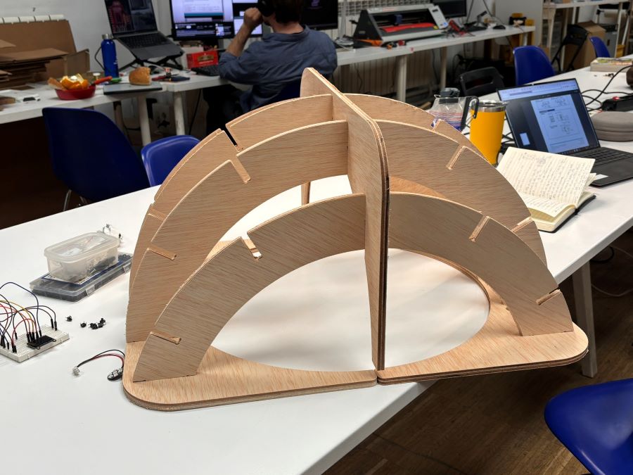
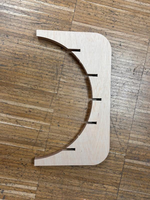
The milling went smoothly and I began to assemble my pieces. Turns out, I encountered a major problem - the
slots where my vertical supports were to fit did not align. Parametrically, the issue wasn't an equal
distribution of
slots on each horizontal piece, but rather the fact that I did not design my slots off of a shared reference
plane, which in this case, is the inside face of the board the horizontal ribs press into.
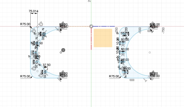
In other words, if I stack the horizontal pieces on top of each other, the slots align, but that's only because
the slots are distributed equally across each rib. Once assembled, their differences in length and in vertical
distribution become painfully apparent.
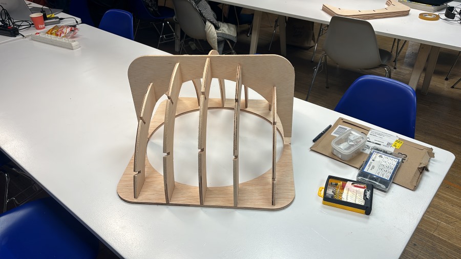
4 more of these vertical pieces are cut and ready to go
Josep the instructor showed me how to redistribute/redraw the slots on my pieces on Rhino to then nest them on the remaining piece of plywood and setup once again for milling. I will go back and correct the slot distribution on Fusion360 to have a proper working file as well.
Takeaways
It was a long week - machine set ups take time and there was a lot of traffic in the lab. It was tough to plan
ahead and prep files to cut while still learning to design on CAD.
Already, I knew my major limitation was the amount of time it takes me to design a file on Fusion, but I spent
most of my time designing because I wanted to cut my final project structure and didn't want to
compromise.
Now that I went through the process, I can do it again (with guidance of course) and correct any mistakes. I
have yet to cut the corrected
pieces, but I am happy I got to go through the process and luckily the pieces are easily swappable.