
Week 6: Embedded Programming
First, starting off with our group assignment in which we compared microntrollers and performed blink tests on
two different boards:
Group
Assignment
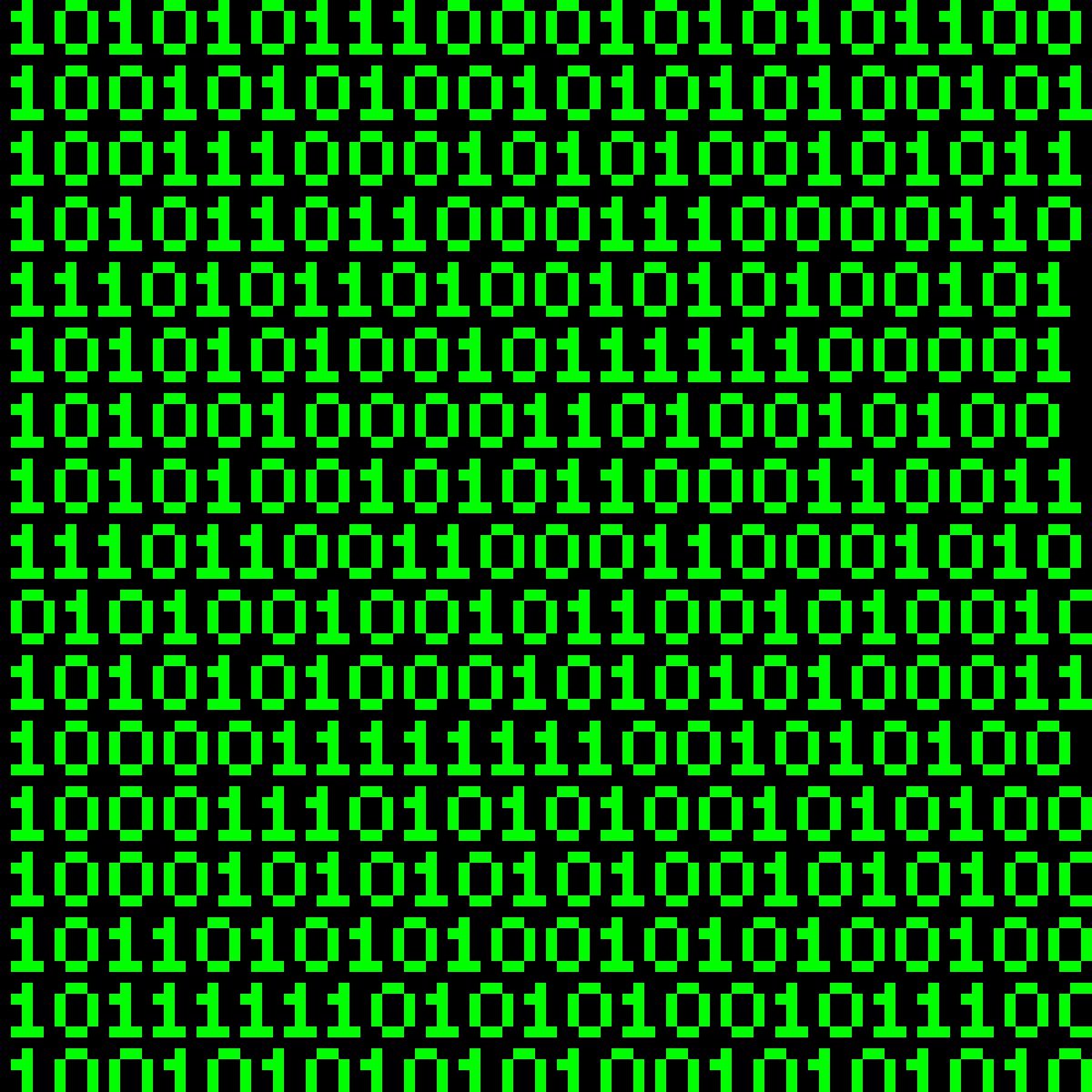
Binary Code
This week, I found that understanding some computer and programming fundamentals was very helpful and actually fascinating. So I went about this week in a kind of winding way, mostly focusing on reading up on the basics and later experimenting with some programming on the Seeed Studio Xiao RP2040 to produce some basic soundwaves.
Binary is a base-2 number system representing numbers using a pattern of ones and zeroes. Early computer systems had mechanical switches that turned on to represent 1, and turned off to represent 0. By using switches in series, computers could represent numbers using binary code.
Each digit in a binary number is called a bit, and each bit represents a power of 2. Binary code is the foundation of all digital technology and computing systems. In computers, binary code is used to represent data and instructions because it can be easily interpreted by electronic circuits that can distinguish between high and low voltage levels, corresponding to the binary digits 1 and 0, respectively.
HIGH = 1
LOW = 0
By arranging these binary digits in different patters, complex data such as text, images, and sound can be represented and processed by computers.
A logic gate is a device that performs a Boolean function, a logical operation performed on one or more binary inputs that produces a single binary output. The primary way of building logic gates uses diodes or transistors acting as electronic switches.
There is a world of information out there and further resources for individual study and practice. Just getting an understanding of the very basics of computers and programming was something I was needing to also "get" computer logic better and see how it's reflected in code and programming languages.
Here are some links I found helpful:
Blink test and beyond
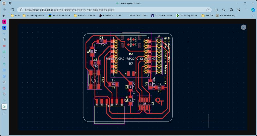
This week we compared microcontrollers and performed a blink test using our Quentorres boards we milled previously, whch is equipped with the Seeed Studio Xiao RP2040. We also tested it on our Barduino boards equipped with the ESP32. You can reference the Group Assignment to find it layed out. I stuck with the Arduino UNO and made a basic synthesizer.
Here's the blink test code I ran first to test our board:
        int led = 26;
        int pushButton = 27;
        int buttonState;
        int ledState;

        void setup() {
          // put your setup code here, to run once:
          pinMode(pushButton, INPUT);
          pinMode(led, OUTPUT);
        }

        void loop() {
        // put your main code here, to run repeatedly:

          buttonState = digitalRead(pushButton);
          if (buttonState == HIGH) {
          digitalWrite(led, HIGH);
          } else {
          digitalWrite(led, LOW);
          }

        }
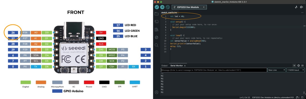
We first start with the pinout to help us identify which pin to declare in the code.
To get the code running on the board, there are a few things you can make sure are checked and can help debug any issues:
- Make sure your USB cables are in fine working condition. Sometimes this is the source problem if your computer port does not pick up on your board.
- Test different computer ports for proper connection.
- Check if Tools/USB CDC on Boot is ENABLED
- Make sure the declared board is the correct version. Select this in Tools > Board > Board Manager.
- Reboot the board with pressing B while plugging the board to your laptop or pressing R
- Restart the board by pressing R.
- Try restering the Arduino IDE or your computer!
Code Breakdown & Explanation
Variable Declarations:
- int led = 26;: Sets the pin number for the LED to 26.
- int pushButton = 27;: Sets the pin number for the push button to 27.
- int buttonState;: Declares a variable to hold the state of the button (pressed or not pressed).
- int ledState;: Declares a variable for the LED state (not used in this particular code but declared).
Setup Function:
- void setup(): This function runs once when you start the Arduino. It's used to initialize variables, pin modes, start using libraries, etc.
- pinMode(pushButton, INPUT);: Sets the push button pin (27) as an input, meaning it will be used to read a signal.
- pinMode(led, OUTPUT);: Sets the LED pin (28) as an output, meaning it will be used to send a signal.
Loop Function:
- void loop(): This function runs over and over again, allowing your program to respond.
- buttonState = digitalRead(pushButton);: Reads the state of the push button (either HIGH or LOW) and stores it in the variable buttonState.
- if (buttonState == HIGH) {: Checks if the button state is HIGH (button pressed).
- digitalWrite(led, HIGH);: If the button is pressed, turn on the LED. } else {: If the button is not pressed.
- digitalWrite(led, LOW);: Turn off the LED.
Uploading the Code Using Arduino IDE
- Connect Your Board: Connect your Arduino board to your computer using a USB cable.
Select Board and Port
- Go to Tools > Board and select your specific Arduino board (e.g., "Arduino Uno" or "Arduino Nano").
- Go to Tools > Port and select the COM port to which your board is connected.
- Copy the Code: Copy the provided code into the Arduino IDE's code editor.
Upload the Code:
- Click the Upload button (the right-pointing arrow icon) in the Arduino IDE.
- Wait for the IDE to compile and upload the code to your board. You should see messages indicating the upload process in the bottom window of the IDE.
- Once uploaded, pressing the button connected to pin 27 should turn on the LED connected to pin 28. Releasing the button should turn off the LED.
Code File
Building a Basic Synthesizer
Materials needed:
- Seeed Studio XIAO RP2040 board or Arduino UNO board
- Breadboard
- Jumper wires
- Piezo buzzer or speaker (for sound output)
- Potentiometer (optional, for adjusting pitch or volume).
Basic step by step Guide
- Connect the Components: Connect the piezo buzzer or speaker to one of the digital pins (e.g., GPIO0) on the XIAO RP2040. If using a potentiometer, connect it to an analog pin (e.g., A0) to control pitch or volume.
- Write the Synthesizer Code: Choose your preferred programming environment (Arduino, MicroPython, or CircuitPython). Write a program that generates sound tones by toggling the digital pin connected to the buzzer. You can create simple waveforms (sine, square, triangle) by varying the pin state at specific frequencies.
- Generate Sound Tones: Use pulse-width modulation (PWM) to create different frequencies. Adjust the PWM duty cycle to change the pitch of the sound. Experiment with different frequencies to create musical notes.
- Optional: Add Potentiometer Control: If using a potentiometer, read its analog value using analogRead(). Map the analog value to a frequency range (e.g., 200 Hz to 2000 Hz) for pitch control. Adjust the volume by mapping the analog value to PWM duty cycle.
- Upload the Code: Upload your synthesizer code to the XIAO RP2040 or Arduino UNO. You should hear sound tones from the piezo buzzer or speaker.
- Experiment and Enhance: Play around with different waveforms (square, sawtooth) for varied sounds. Add more features like envelope shaping (attack, decay, sustain, release) for more realistic tones. Explore MIDI input/output for connecting your synthesizer to other devices.
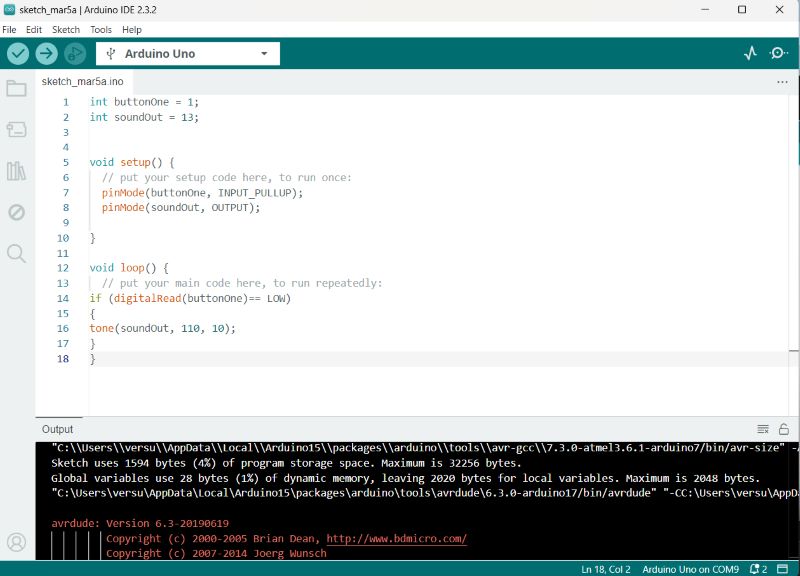
Code to generate soundwave using Arduino IDE:
// Generate a square wave on pin 9
  digitalWrite(28, HIGH); // Set the pin high
  delay(1);            // Half period duration (adjust as needed)
  digitalWrite(28, LOW);  // Set the pin low
  delay(1);            // Half period duration (adjust as needed)
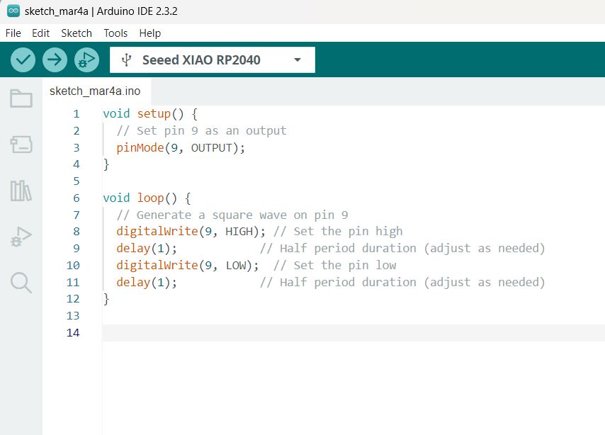
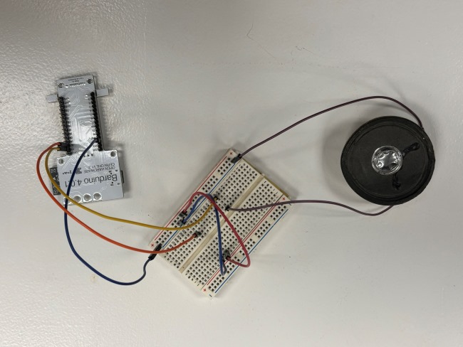
In the above image, the beeping is continuous, so I added a button in order to control the sound.
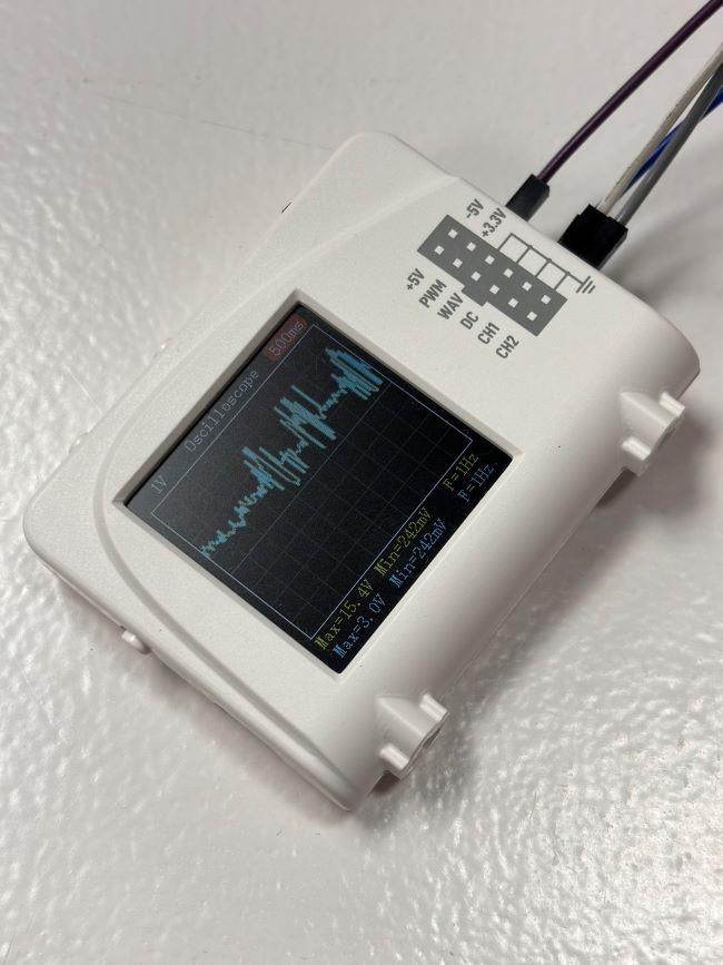
I also experimented with getting a reading on an Oscilloscope using the setup of a Fab Lab member who was working on a pre-amplifyer.
Finally, I experimented on producing sounds with the touch sensors on the Barduino board and triggered different beeps: