Week 4:
Electronics Production
This week, we learned to mill our own PCBs. Here is a link to our group project:
Electronics week group assignment
What is electricity?
We were introduced to the fundamentals of electronics:

Electricity is a form of energy that plays a crucial role in our daily lives. Electricity is the flow of electrons. It's a fundamental part of nature, and we use it extensively for various purposes. All matter consists of atoms, which have a nucleus containing positively charged protons and uncharged neutrons. Surrounding the nucleus are negatively charged electrons. When an atom gains or loses an electron due to an external force, it creates an electric current.
Electron Flow

Electron flow is the movement of negatively charged particles called electrons through a conductor, such as a wire. Electron flow is the basis of electric currents, which power many devices and machines in our world. There are two types of electron flow; direct current (DC) and alternating current (AD). Conventional current flows from the positive terminal to the negative terminal. This is the opposite direction to electron flow.
AC/DC

DC is when electrons flow in one direction, while AC is when electrons switch directions periodically. AC and DC are different types of electricity. If you look on the plugs of your electrical devices, you should find labels from the manufacturers that tell you what the product is designed to handle.
In AC, electrons do not flow in a continuous loop, instead, they alternate between moving forward and backward, just like the tide of the sea.
In DC, electrons flow in one direction only, directly from one terminal to the other. You can think of this like the flow of water down a river. DC is easier to control and allows circuits to be smaller and more compact. We can convert AC to DC using a device known as rectifier. We can also convert DC to AC using an inverter.
Ohm's Law
Ohm's Law describes the relationship between voltage, current and resistance. It is a fundamental law of electricity that states that the current through a conductor between two points is directly proportional to the voltage across the two points.
If voltage increases, then current increases provided the resistance remains the
same.
If the resistance
increases, then the current decreases provided the voltage is held constant.
Voltage and current are
proportional to each other. Resistance and current are inversely proportional to each other.
Electric Force

Electric force is a non-contact force. The electric force acts over distance separating the two objects.
Electric force is an action-at-a-distance force.
The space surrounding a charged object is affected by the presence of the charge; an electric field is established in that space.
The electric field direction is always directed away from positive source charges and towards negative source charges.
Conductance

Conductance is a measure of how easy it is for a particular voltage to force a current through a
material.
It is the inverse of resistance, which is a measure of how difficult it is for a current to
pass.
Conductance is measured in Siemens (s). You can calculate the conductance of a material by dividing the current by the voltage, or by taking the reciprocal of the resistance. Conductance is the inverse (or reciprocal) of electrical resistance, represtented as:
1/R
For example, if a material has a resistance of 10 Ohms, its conductance is 0.1 S
Resistance

Resistance is the property of an electrical component to resist the flow of electric current. Resistance
is measured in ohms, symbolized by the Greek letter omega (Ω). Resistance is calculated by dividing the
voltage across the component by the current through it, according to Ohm's Law. Resistance depends on factors
such as the material, length, cross-sectional area, and temperature of the component. Resistance can be used to
control the amount of current and heat in a circuit.
Voltage

Voltage is a measure of the difference in electric potential between two points. It indicates how much
work or energy is needed to move a unit of electric charge between those points. It is also known as electric
pressure or electric tension, and it is the force that pushes electric current through a circuit. Voltage is
measured in volts (V).
Current

Electric current is the flow of charged particles, such as electrons or ions, through a conductor or a
space. The unit of electric current is the ampere (A), which is equal to one coulomb charge per second. Electric
current can be direct (DC) or alternating (AC), depending on the direction of the charge flow. Electric current
produces magnetic fields, heat and can power various devices.
Load

The device which takes electrical energy is known as the electric load. In other words, the electrical
load is a device that consumes electrical energy in the form of the current and transforms it into other forms
like heat, light, work, etc.
In electricity, load is the term used to describe the power consumption or demand of a device, appliance, or circuit. Load can be measured in watts (W) or kilowatts (kW), which are units of power. The higher the load, the more electricity is required to run the device or appliance. For example, a light bulb may have a load of 60W, while an air conditiner may have a load of 2kW.
Load can vary depending on the type and number of devices or appliances that are turned on, as well as the time of day and season. Some types of load are resistive, inductive, or capacitive, depending on how they affect the current and voltage in a circuit.
Polarity

Polarity in electricity is a term used to describe the flow or direction of the electrcal current. It is
determined by the positive and negative poles of the electricity source, such as a battery or power source.
Current flows from the positive pole to the negative pole. It is used to define the state of a body or system
with respect to other bodies or systems. It is a relative quantity.
Electric polarity is classified in two ways:
- positive polarity
- negative polarity
The polarity of a body or system that has a greater number of electrons is considered the negative polarity. And the polarity of the remaining body or system is considered the positive polarity.
Anode and Cathode
Anode and cathode are the two types of electrodes. (An electrode is a conductor through which electricity
enters or leaves an object, substance or region). They are defined by the flow of current. An anode is the
electrode where electricity moves into the device from an external circuit. A cathode is the electrode where
electricity is given out or flows out of the device. The anode and cathode charge are positive and negative
respectively. The roles of the electrodes as anode and cathode can be reversed depending on the direction of the
current.
Circuits
When we connect components in an electrical circuit, we can connect these in series, in parallel, or we
can combine these to make a series parallel circuit.
A series circuit is a simple electrical circuit that only has one path for current to flow through.
A parallel circuit is an electrical path that branches so that the current divides and only part of it flows through any branch.
Resistance in Series Circuits
Each component will have a certain resistance. The resistance opposes the voltage being applied. It reduced the voltage or 'pressure'. We measure resistance in the unit of Ohm.
The resistor creates a more difficult path for the electrons to flow through and as they flow through they will collide with other electrons. This collision will convert the energy to heat. The same amount of electrons will enter and exit the resistor, but they'll just have less energy or 'pressure', as there's been a voltage drop.
We can calculate the voltage drop across each resistor individually:
voltage drop (v) = total current (a) x component resistance (ohm)
In series circuits, we find the total resistance for the circuit by adding together all the resistances.
Wire also adds some resistance to the circuit, but this is very small. You might need to account for this
depending on how accurate your design needs to be.
Resistance in Parallel Circuits
Resistors are said to be connected together in parallel when both of their terminals are respectively connected to each terminal of the other resistor or resistors.
Unlike series circuits, in a parallel resistor network the circuit current can take more than one path, as there are multiple paths for the current. Resistors in parallel circuits are classes as current dividers.
Since there are multiple paths for the supply current to flow through, the current may not be the same through all the branches in the parallel network. However, the voltage drop across all of the resistors in a parallel resistive network IS the same. Resistors in parallel have a common voltage across them and this is true for all parallel connected elements.
Current in Series Circuits
Current is the flow of electrons. It's like water that flows through a pipe. The higher the current, the more electrons are flowing. This is measurees in Amperes, shortened to Amps. We measure current by placing an Ammeter into the circuit for the electrons to flow through. We can connect a multimeter into the circuit to also read the current. it must be placed into the circuit. It will add a small resistance into the circuit but we can usually just ignore this.
We can calculate current using the formula:
Current (A) = Voltage (V) / Resistance (Ohm)
In a series circuit, the current is the same throughout the entire circuit.
Current in Parallel Circuit
In parallel circuits, when a current reaches a junction in the circuit, it splits up and some current flows along each route. When two branches of a circuit meet, the current combines again. The total current flowing through the cell can be found by adding the individual currents flowing through each branch.
Voltage applied will vary the current, which depends on the resistance of each branch and how many branches are connected.
Voltage in Series Circuits
Voltage is the pushing force of electrons. It's like pressure in a water pipe. The higher the pressure, the more water can flow. The higher the voltage, the more electrons can flow.
When we measure voltage, we're measuring the difference (por potencial difference) between two points. If we read across a 1.5V battery, we'll get a reading of 1.5V. If we try to measure the same side, we wouldn't read any voltage. We can only measure the difference between two points.
Unlike current, where it's the same throughout the circuit, voltage will be different throughout a series circuit. Voltage is reduced by each resistor, so the resistor creates a voltage drop.
Voltage in Parallel Circuits
In parallel circuits, the voltage is the same anywhere in the circuit. When calculating voltage in parallel circuits, the value is the same; it's the voltage of the battery.
Power Consumption in Series Circuits
How do we calculate power consumption?
Formulas:
1. Power (watts) = Voltage2 / Resistance (ohm)
2. Power (watts) = Voltage (v) x Current (a)
How can a resistor consume power? As the resistor is creating a voltage drop, the electrons are losing energy. Where is this energy going? The electrical energy is being converted into heat, so the power consumption is the heat being dissipated from the circuit.
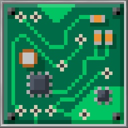
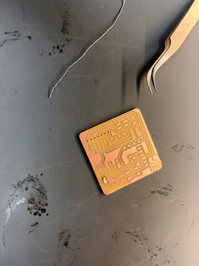
PCB Milling, Soldering and Button Test
In order to mill our PCBs this week, we used a Roland SRM-20 CNC and 1/64" & 1/32" bits. We started by uploading our modified Quentorres board files one by one on MODS
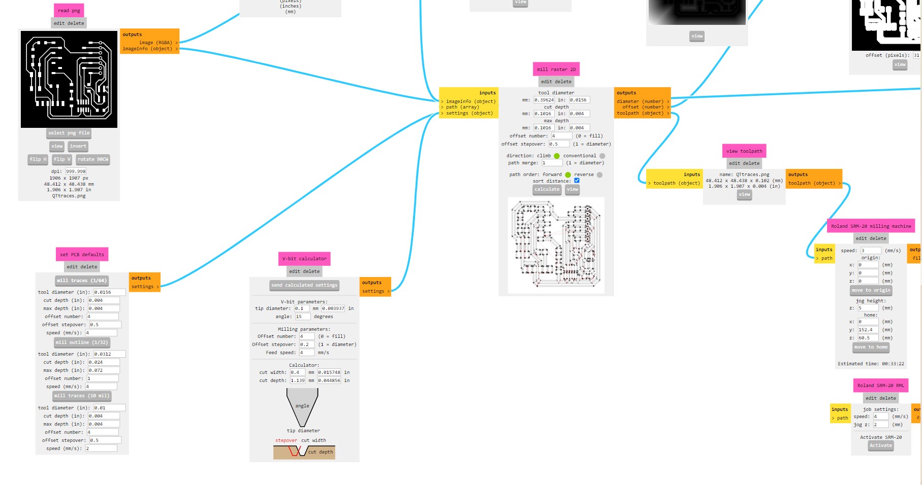
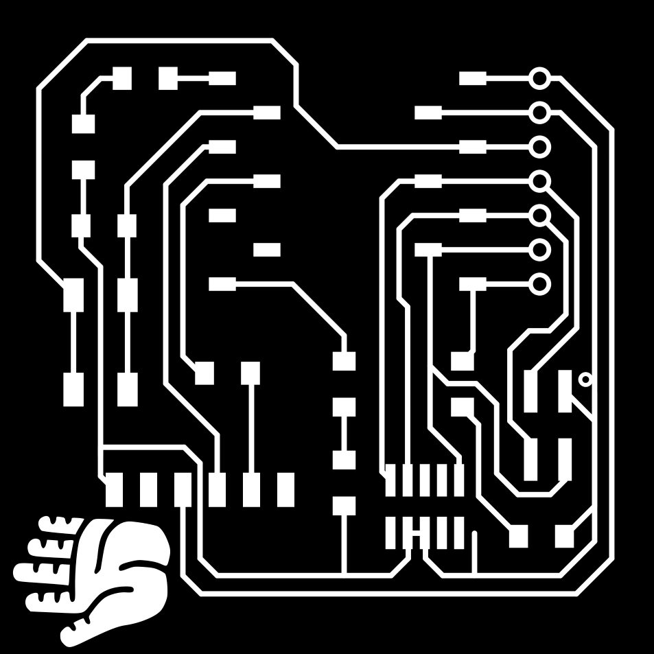
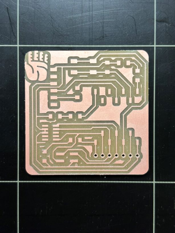
Once we adjusted settings in the MODS, we uploaded the file to the IAAC cloud and ran it through the computers connected to the CNC, set our bits and axis per job. Both the outline and the holes in the PCB were done using the 1/32" bits, and the circuit was traced using the 1/64" bit.
- Fix the board to the "sacrificial" bed with double sided tape. Go over the edges with tape to avoid uneven surfaces between the bed and the board piece.
- Set the bit that will cut your traces first. Then you can go on to machining the holes and then cutting the outline.
- Traces: 1/64, speed: 3, origin: 0.0.0 and jog height: 6, depth: 1.75
- Holes: 1/32, speed:1.5, origin: 0.0.0 and jog height: 6, depth: 1.75
- Outline: 1/32, speed 0.5, origin: 0.0.0 and jog height: 6, depth: 1.75

MODS Specifications:
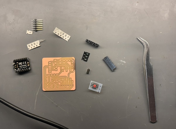
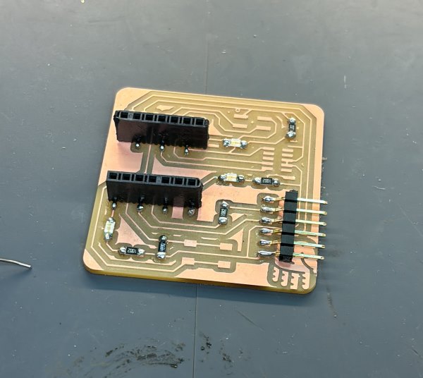
These are the bits we soldered onto our PCB:

Good old soldering

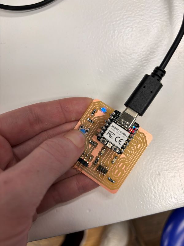
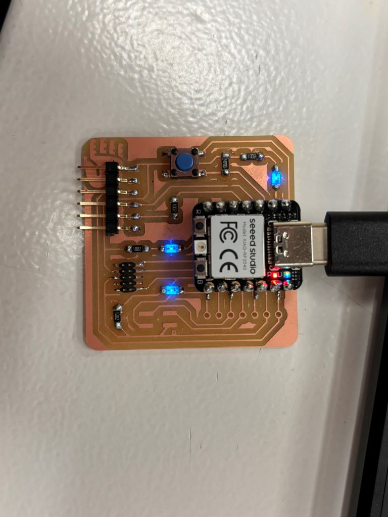
Testing the chip via blink and button test on Arduino
/*
  Button

  Turns on and off a light emitting diode(LED) connected to digital pin 13,
  when pressing a pushbutton attached to pin 2.

  The circuit:
  - LED attached from pin 13 to ground through 220 ohm resistor
  - pushbutton attached to pin 2 from +5V
  - 10K resistor attached to pin 2 from ground

  - Note: on most Arduinos there is already an LED on the board
    attached to pin 13.

  created 2005
  by DojoDave
  modified 30 Aug 2011
  by Tom Igoe

  This example code is in the public domain.

  https://www.arduino.cc/en/Tutorial/BuiltInExamples/Button
*/

// constants won't change. They're used here to set pin numbers:
const int buttonPin = 27;  // the number of the pushbutton pin
const int ledPin = 26;    // the number of the LED pin

// variables will change:
int buttonState = 0;  // variable for reading the pushbutton status

void setup() {
  // initialize the LED pin as an output:
  pinMode(ledPin, OUTPUT);
  // initialize the pushbutton pin as an input:
  pinMode(buttonPin, INPUT);
}

void loop() {
  // read the state of the pushbutton value:
  buttonState = digitalRead(buttonPin);

  // check if the pushbutton is pressed. If it is, the buttonState is HIGH:
  if (buttonState == HIGH) {
    // turn LED on:
    digitalWrite(ledPin, HIGH);
  } else {
    // turn LED off:
    digitalWrite(ledPin, LOW);
  }
}
/*
  Blink

  Turns an LED on for one second, then off for one second, repeatedly.

  Most Arduinos have an on-board LED you can control. On the UNO, MEGA and ZERO
  it is attached to digital pin 13, on MKR1000 on pin 6. LED_BUILTIN is set to
  the correct LED pin independent of which board is used.
  If you want to know what pin the on-board LED is connected to on your Arduino
  model, check the Technical Specs of your board at:
  https://www.arduino.cc/en/Main/Products

  modified 8 May 2014
  by Scott Fitzgerald
  modified 2 Sep 2016
  by Arturo Guadalupi
  modified 8 Sep 2016
  by Colby Newman

  This example code is in the public domain.

  https://www.arduino.cc/en/Tutorial/BuiltInExamples/Blink
*/

// the setup function runs once when you press reset or power the board
void setup() {
  // initialize digital pin LED_BUILTIN as an output.
  pinMode(LED_BUILTIN, OUTPUT);
}

// the loop function runs over and over again forever
void loop() {
  digitalWrite(LED_BUILTIN, HIGH);  // turn the LED on (HIGH is the voltage level)
  delay(1000);                      // wait for a second
  digitalWrite(LED_BUILTIN, LOW);   // turn the LED off by making the voltage LOW
  delay(1000);                      // wait for a second
}
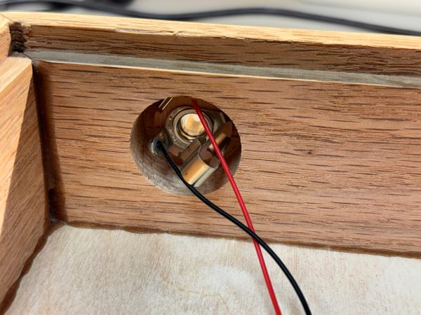
Lastly, here are some images of my Index Drums Doombox that I opened this week to take a look inside. It's a piezo mic attached to an output. This gives me an idea of one thing I'm going to do with my final project.