Week 16 - System Integration
Wood cover + Electronic casing
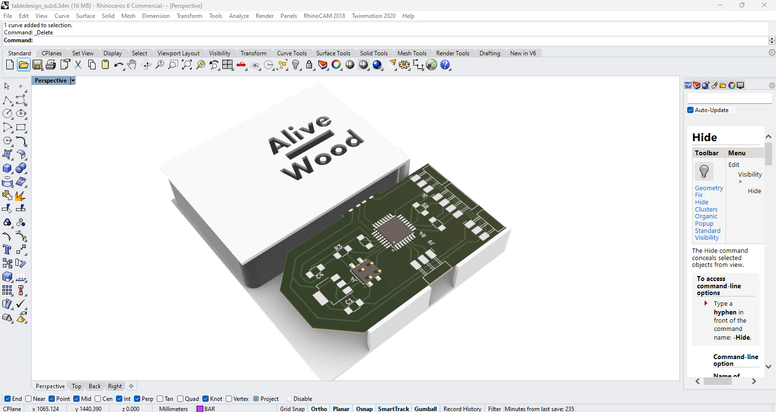
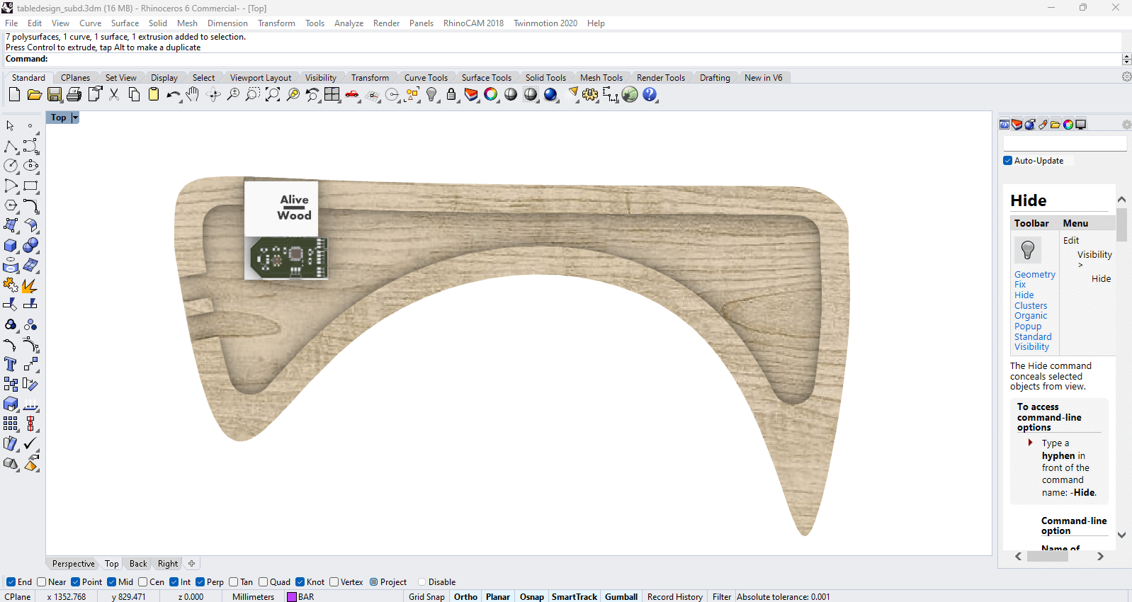
The design phase began with detailed modeling in Rhino to visualize the integration of electronic components within the wooden structure. This involved creating precise 3D models of the PCB and designing the casing to house the electronics securely.
3D Modeling
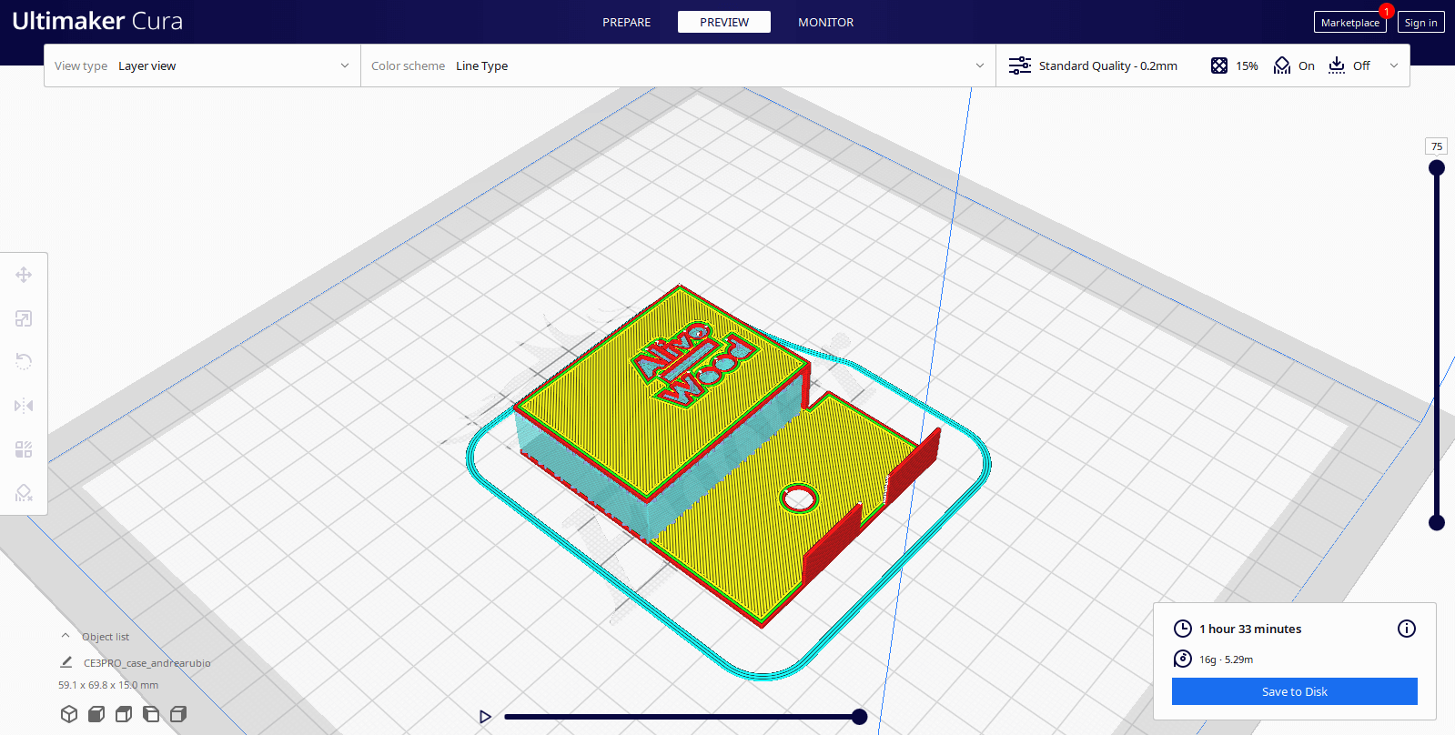
The next step involved preparing the 3D model for printing using Ultimaker Cura. The slicing process optimized the model for 3D printing, ensuring the case would be printed with the necessary precision and strength.
Once the slicing was complete, the case was printed, providing a durable housing for the PCB and other electronic components.
3D Printing: PCB case
The next step was preparing the 3D model for printing using Ultimaker Cura. The slicing process optimized the model for 3D printing, adjusting parameters such as print quality, infill density, and estimated print time.
Once the model was ready, the 3D printing process began with Creality Ender Pro 3 printer using PLA. The video shows the process in action, where the printer builds the case layer by layer.
Laser Cutting: Pinout + Project info
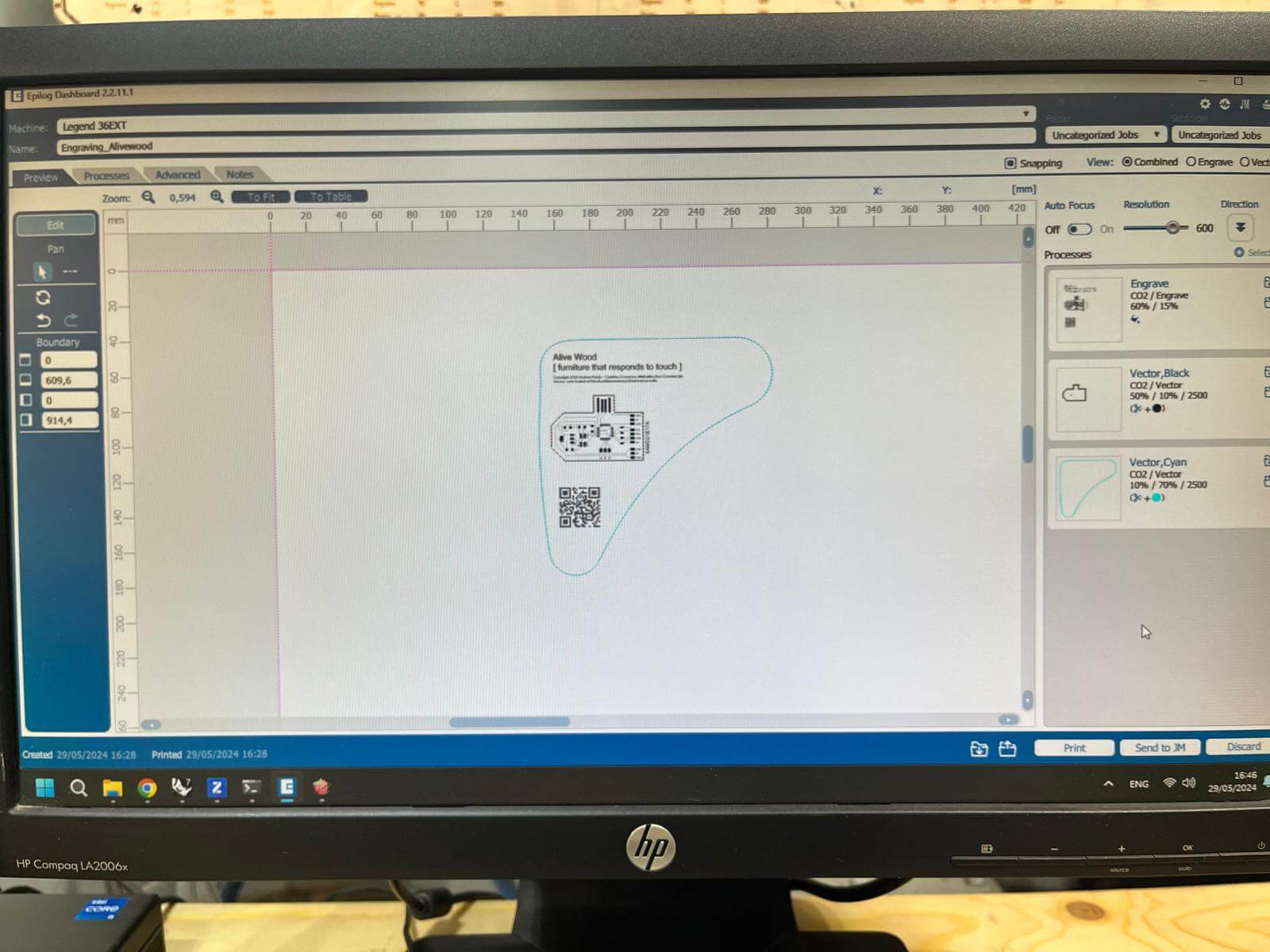
Initial Design Setup: The design includes an engraving of the electronic circuit and a QR code along with the "Alive Wood" branding.
Software Configuration: Dídac suggested to use another laser cutting machine which has better engraving quality. The settings are set to 60% power and 10% speed, while the vector cutting are configured as per the material's specifications.
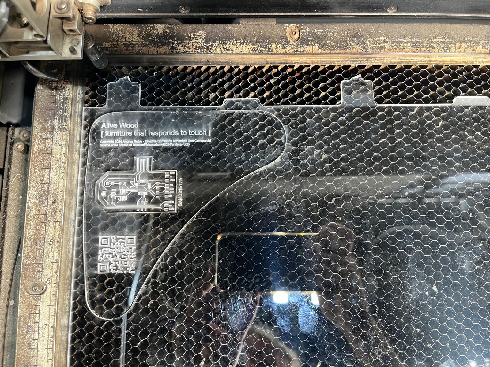
Material Placement: Transparent acrylic of 5mm thickness, is placed in the laser cutter. The setup includes aligning the material properly and securing it to prevent movement during the cutting process.
Assembled Piece: The final acrylic piece, now engraved and cut, is ready for integration fitting it into the wood casing.
CNC: Wood cover
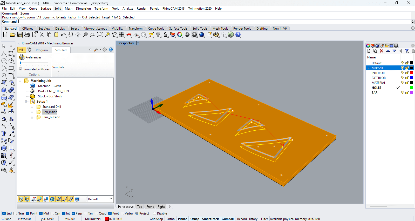
The milling job is set up in RhinoCAM 2018, using a 3-axis CNC machine with a box stock setup. The following images illustrate the different stages of the toolpaths used for this milling project. I used scrap wood from previous projects and the same parameters for every function, you can check the documentation from Week 07:CNC.
Drilling
The drilling operation is configured for precise hole placement. Each yellow point represents a drilling location, and the red lines indicate the toolpath between these points.

Interior Cuts
The interior cuts are designed to carve out the inner sections of the design. The toolpath ensures clean and precise cuts within the material.
Exterior Cuts
The exterior cuts outline the main shape of the project. These cuts define the outer boundaries and are crucial for achieving the final shape.

Simulation
CNC milling process, showing the progression through drilling, interior cuts, and exterior cuts.
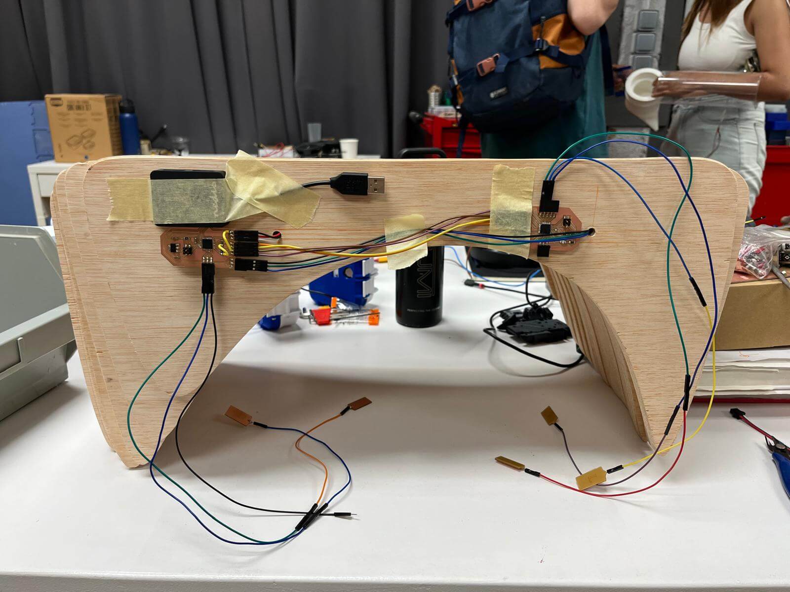
Final Integration
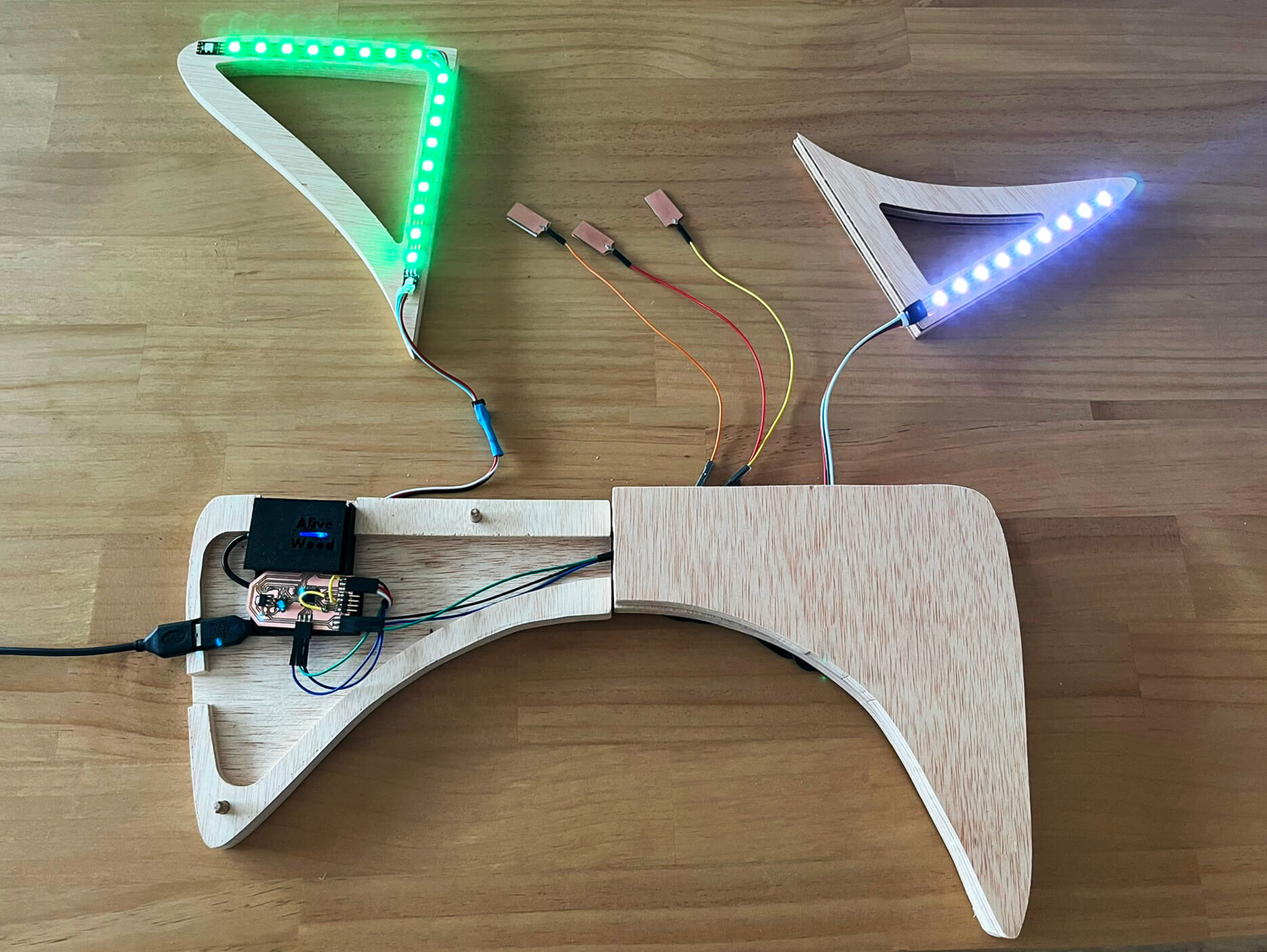
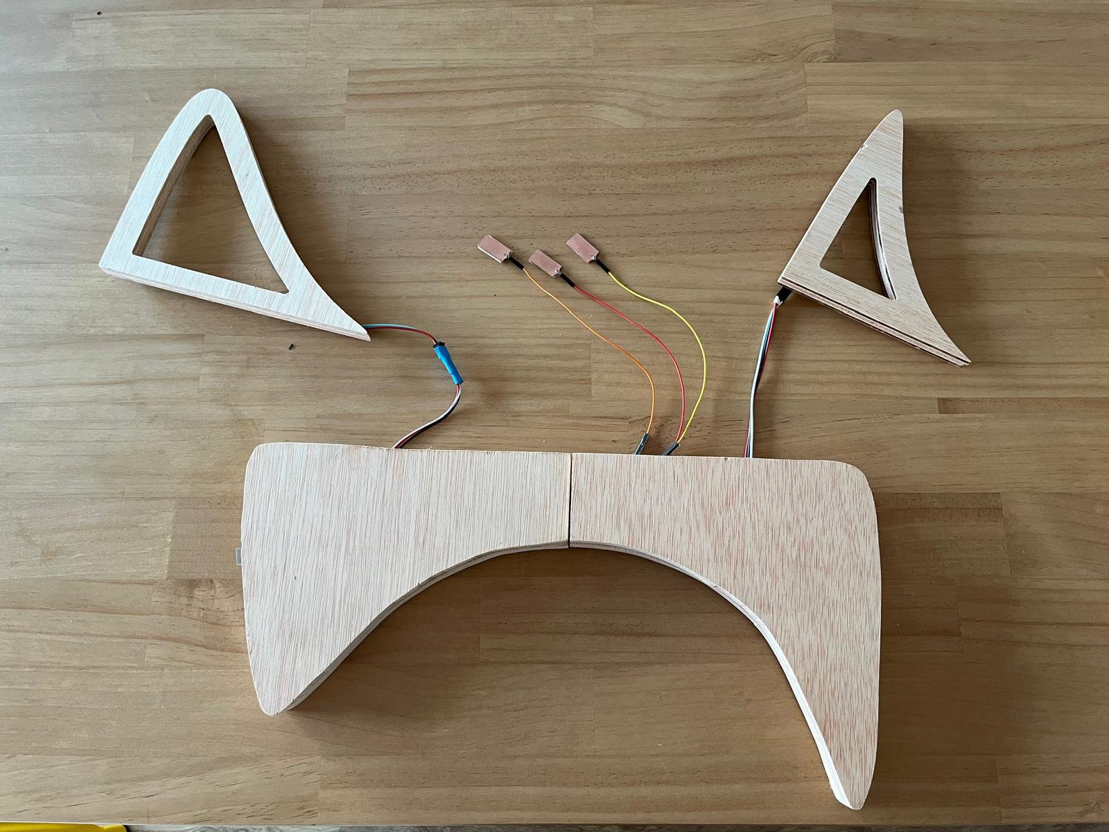
After preparing the wooden structure and 3D-printed case, the components were assembled. The PCB was secured in the case, and wiring for the capacitive touch sensors and LED strips was meticulously arranged to ensure functionality and aesthetics.
The finished product featured a sleek design with all the interactive elements seamlessly integrated but with easy access in case of maintainance.
Resources
Josep Martí // Fab Lab Barcelona lead instructor
Philipp Wienkamper // IAAC Fabrication Laboratory
Dídac Torrent // IAAC Fabrication Laboratory
Files
Download Rhino and cutting files in ZIP package here.