3. Moulding & Casting
This week we are utalising CNC milling to 3D mill a wax mould which we can use to make a silicone mould to use with other materials.
This week was quite difficult to model around as there is many things to consider when modelling a mould. This was also some issues we faced with getting the CNC mill running.
Modelling for Moulding
Here are some topics you need to keep in mind:
Safety
It is important to read and follow the pracautions set out in the material data sheet. You can find more information on this on this weeks group project page.
The silicones I will be using are:
Exposure Controlls
First Aid
Read the full Safety Data Sheet here
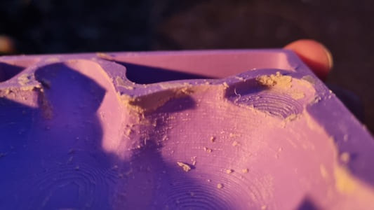
Mould Making using FDM
Although not part of the brief I wanted to try using my FDM 3D printer to make a mould which I could then use to cast selfleveling cement or plaster.
Even with very small layer height it still leaves a noticible texture which will be transfered into whatever it casted into it. For my use case this does not matter.
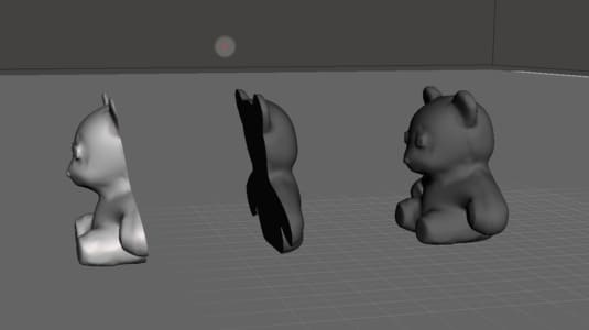
I was planning to use a editted version of this teddy bear uploded by suzujoji on thingyverse. This is because I am use to modelling mechanical parts not cute little models although I did have an attempt at it in meshmixer.
There are unfortunatly a few features which makes it not ideal for moulding such as the feet and the chin. Therefore I opened it in meshmixer and started use the tools to extend certain areas to fill in the overhangs and smoothen off angle which would be potentially problematic.
Once I was done I sliced the model through a plane which went through the ears and through the middle of the body and imported them into cura slicer. This was an attempt at finding any overhangs that could be in the mdoel. By setting the support angle to 1 degree the software should generate supports at these areas.
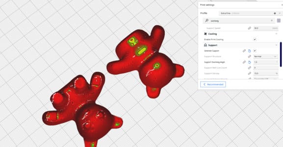
I went back and edited the issues it pointed out then brought the models into Fusion 360.
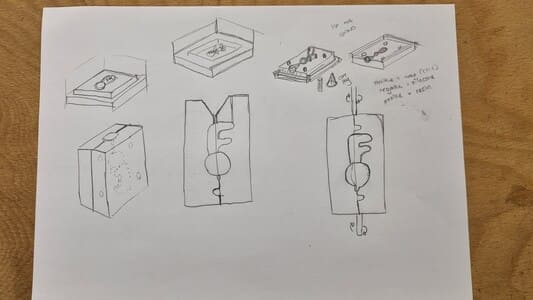
Here are the finished mould design
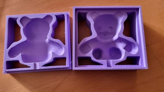
This test wasn't entirely successful as you will see in the results of my test pours.
Test Pours
I modelled a basic diamond cube shape to practice the process and try out different release agents.
There was a design flaw that I did not put in a air hole which meant the air couldnt escape and made filling the moulds very difficult. The overlap to join the two parts together should have gone all around as it leaked without a clamp to push the two sides together.
I tried using some cooking spray and vaseline. Cooking spray seemed marginly more successful but I will likly buy some silicone spray if I plan to do this often.
Teddy Bears Pours
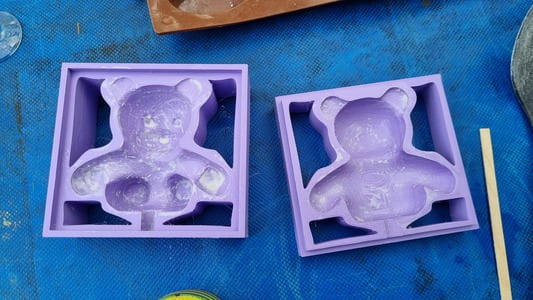
I created a mould using the edited teddy file. Added a full lip for alignment and a large funnel to add the mixture into the mould. I also added some air hole which made things much easier.
I made cut outs to save on plastic, however I would avoid this in the future as the air holes were not on the same level as the fill hole which meant them leaked a bit.
I used the cooking spray as a release agent.
Used some cheap electrical tape to encorage the mould to stay together and limit leaks.
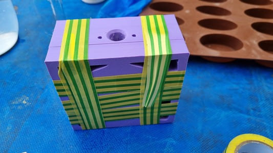
The concrete I used was Blue Circle Masterlay Floor levelling compound. On the bag the ratios are 20000g:4000ml, so a 20:4 of powder to water. However you can dilute it further without issue from my experience.
The plaster I tried was Thistle OneCoat Plaster. The ratio of 7500g:4500ml, 15:9. I had to dilute this much more as it was a paste and did not pour, however it still set fine. The plaster by nature is quite fragile.
Results
The bears released quite easily on one side, however it took some effort to remove the other side. This inevitable caused some damage, but this is more just demonstrating a bad mould and not ideal mould release.
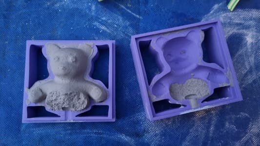
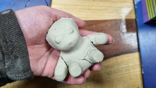
You can see a missed overhang at the neck
I decided that it would be best to 3D model my own model to mill as this bear was causing issues.
Milling Out of Wax
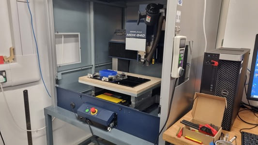
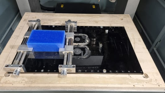
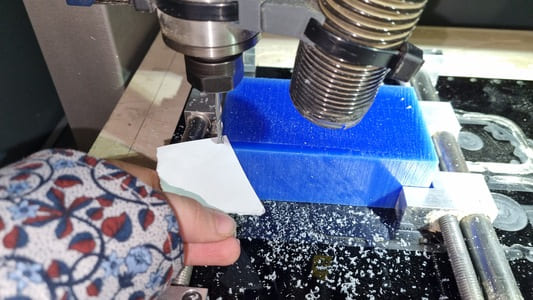
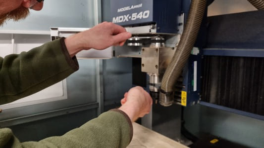
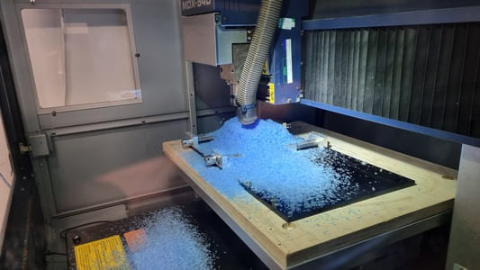
We have a MDX540 CNC mill which we will use for milling the wax.
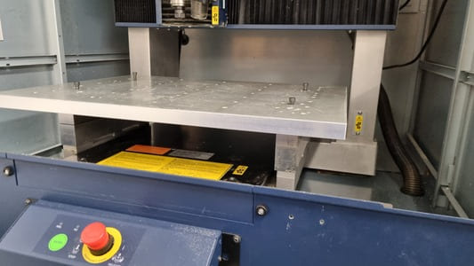
There was quite a bit of set up required before the machine could be used. I put extenders under the base plate to raise up the bed. Fastened down a wooden wasteboard using plastic screws. Then used the techsofts self centering vice to hold the wax block from the sides. We manually joged and used the head to mill two holes to make sure it was perfectly horizontal to the machines X axis.
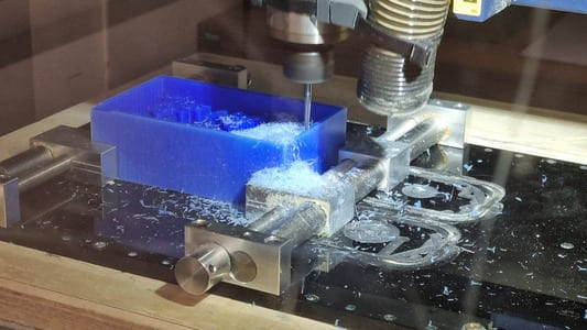
I will be using a 4mm flat end mill for the roughing cuts and a 2mm tapered ball end mill for the finishing. The tapered mill was not a great decision as the depth on the cut was quite dead so the taper was quite extream at the top and as the retaining walls were already quite thin it caused some damages.
We pre-milled a flat surface on the edge of the top face of the wax block so we could zero the z axis accuratly after the tool change as the roughing pass would flatten out this face.
Toolpath Generation
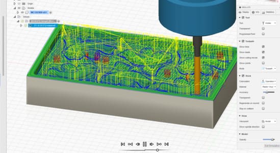
I initially started in Fusion 360 trying to use adaptive clearing for the roughing path and then a 3D parallel pass for the finishing passes, however I had some issues. The simulated paths were not acting as expected so I opted to use the software that came with the CNC machine.
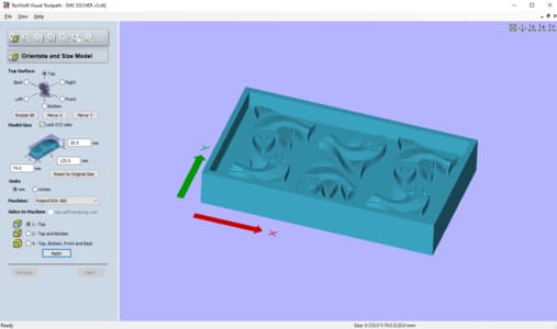
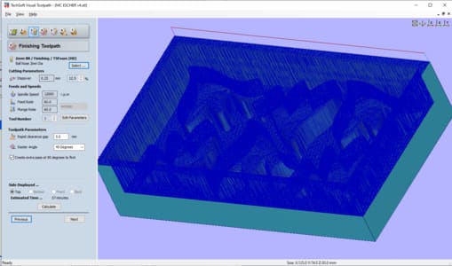
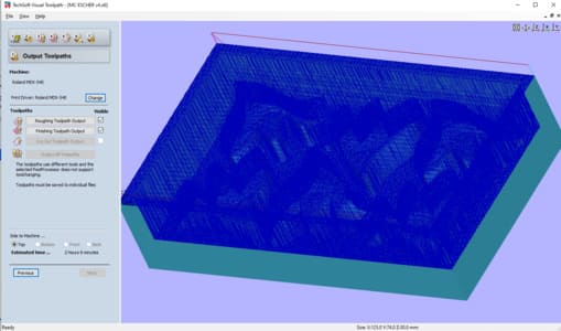
TechSoft Visual Toolpath is quite dated and has limited machining options it is able to do roughing, finishing and cutout jobs. There are benefits in its simplicity.
I made refrence to John Story's (my tutor's) page for what settings I should use.
You open the stl in the software. The default settings for the set page is perfect in this case.
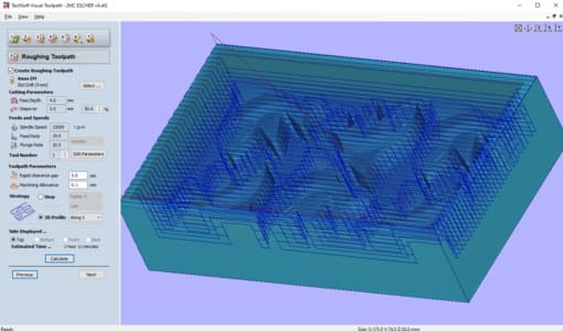
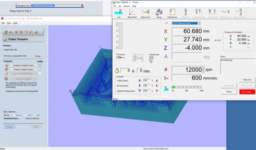
Roughing we choose the 4mm End mill. Pass depth of 4mm, stepover of 2mm, spindle speed of 12000 and 10m/s feed and pluge rate. Note the default units is mm/min be aware if you are getting several hour long milling estimations.. Rapid clearance gap of 5mm and machining allowence of 0.1mm. The strategy if the machining is 3D profile.
Fininshing we use a 2mm ball end mill with a step over of 0.25, spindle of 12000, 60m/s feed rate and plunge rate. Rapid clearance of 5mm, raster angle 45 degrees and click the check box for create extra pass at 90 degrees to first.
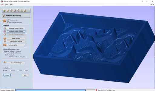
You can them preview the machining to double check it is doing something sensible.
Milling
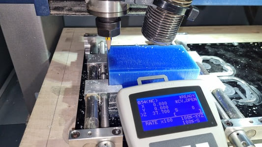
We open up the VPanel for the MDX540. One issue we had was that it was in the wrong mode. NC gcode is quite normal however the Vistual tool path uses RML. Need to make sure it is in the correct mode when the software starts. It seemed to be milling the design at a small scale.
The machine was homed. Used a pointed bit or pencil to move the head to the x-y zeros in the bottom left corner. To zero the z we slowy stepped the head down in 0.1mm steps till it gripped a piece of paper, then removed the paper and made one last step before zeroing.
You use two spanners to losen the nut and collet in order to insert the tools.
Then on the output toolpaths page of the tool path visualiser you just click on the job you want to complete.
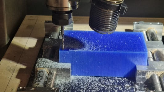
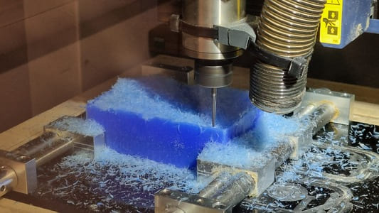
Roughing made a lot of chips.
Roughing result
Finishing first angle
Finishing second pass at 45 degrees to first.
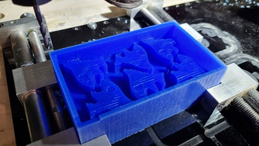
Finishing result
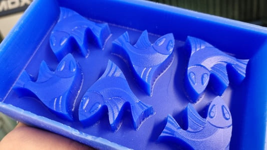
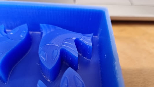
Unfortunatly the side got a bit damaged from the tapered bit pressing against the thin wall however this can be temporarily fixed with tape when doing the silicone pours.
All the thin features turned out well on the top of the fish with a slight texture remaining. Probably could have make the finishing path slightly finer.
Silicone Pour - Food Safe
I had done some test pours of the silicones and resins we had in stock and they all cured however some are probably getting a bit old as the silicones were quite gloopy.
I set up a covered work station and put on the appropriate PPE as dicussed earlier.
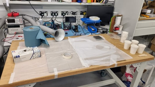
I started with food safe silicone so to keep everything kosher.
Measured 200g (100g A 100g B) as its a 50:50 ratio and started mixing.
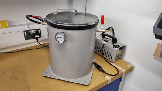
I then pored into the wax mould and put a paper colar to keep the foam in. I then placed it into the vacumme pot. You place on the glass lid, switch on the pump and close the valve.
The mixture foamed up alot. I think the thickness of the mixture inhibited the bubbles from popping easily.
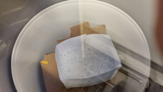
As the pot life was 25mins I took it out before everything had settled. When I took it out of the chamber I had to scrape the sides of the colar as too much mixture stuck to it, the mould was half empty.
This was quite diappointing as it introduced a could of bubbles and caused the bottom surface to be very uneven as the mixture didnt level off.
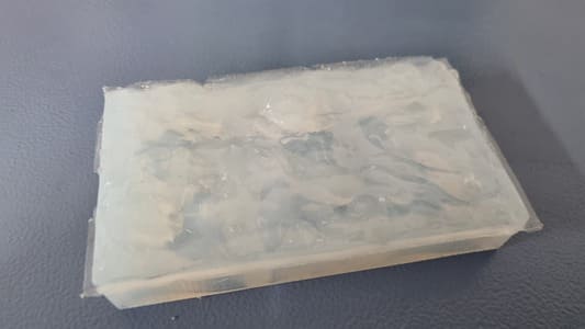
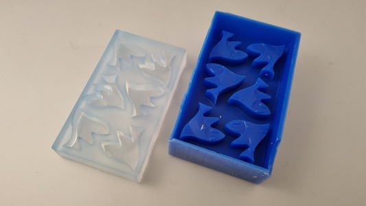
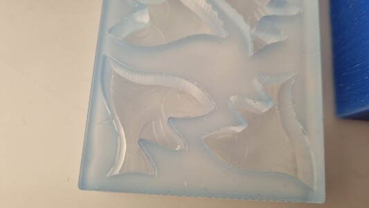
It did however cure and de-mould successfully.The casts of the fish looked great.
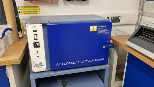
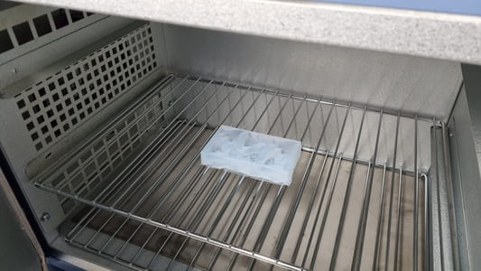
I did the recommended final cure process of cooking the mould in our CR Clarke 200FD Oven. The instrustions were 2hrs at 80 degrees c and then another 1hr at 100 degrees c. The mould came out looking very similar.
I then cut off the flash from the edges.
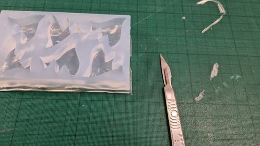
Here is the result
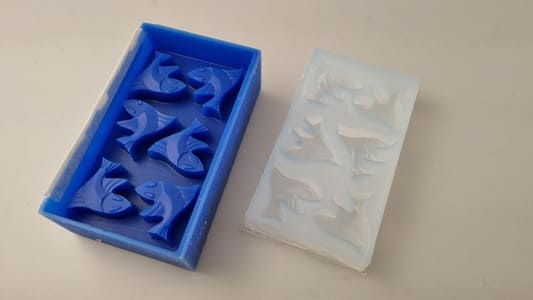
Silicone Pour - AS40

This silicone is a another two part mix at a ratio of 100:10. I therefore used 180g and 18g of catalyst.
I mixed up the parts then I decended to run a first degas in the mixing cup then pour into the mould. This mixture had a similar problem of being very thick but it was a bit better than the other silicone as it could pour.
I used the same set up of a paper colar on the wax mould and poured in the silicone in as slow a trickle as I could.
I then degas again. The foam was very stubborn but when I released the vacume the bubbles settled out.
There was some miniscule bubbles but I left it as the pot life is 30mins.
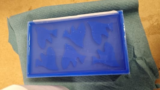
These did end up settling
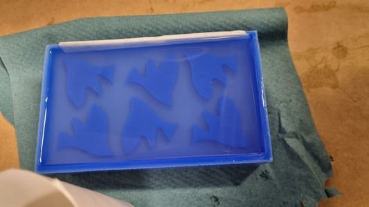
Here are the finished results:
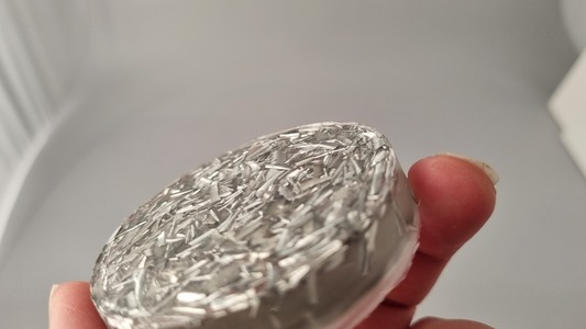
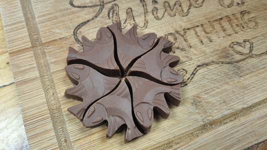
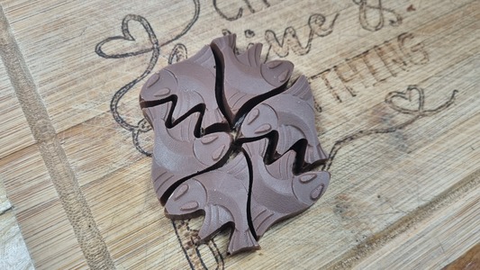
I used the glass clear resin to create some fish and used some metal swarf to decorate the pours.
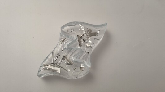
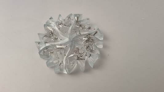
Even a lot of swarf could be encased successfully.