9. Electronics Design
This week we are learning how to use EDA’s to design PCBs for CNC milling or sending off to a board house to be produced en mass.
During week 5 I designed my own keyboard using KiCad which was then sent off to be produced by JLC. You can read more about it on week 5 and SS Keyboard pages.
We are also tasked with using test equipment to observe a microcontroller working.
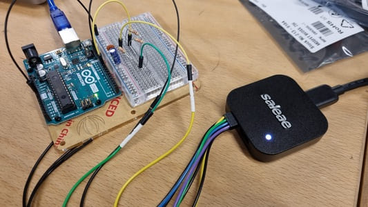
Saleae
Saleae is a logic analiser and is used to decode protocols like SPI, I2C and serial.
I installed Saleae’s software, Logic 2 and followed the instructions for ubuntu.
We connected the saleae up to a arduino uno and observed the transmission during a few different operations using the default example code from arduino.
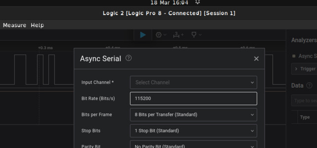
We needed to set the bit rate to match the arduino.
Blink
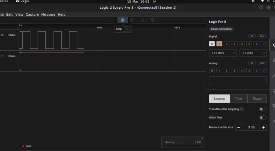
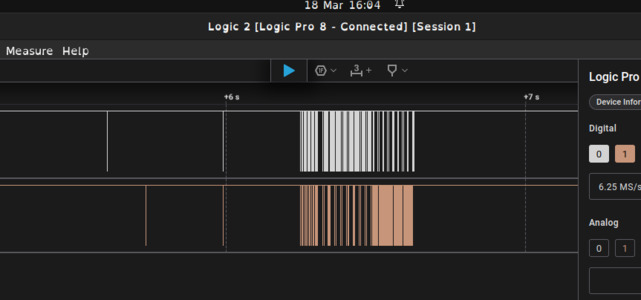
We started with the blink program. This is the data being recorded in real time.
The square wave shows when the signal is high and when it is low. High depends on the device, it can be 3v, 5v, 12v etc., low refers to ground. In this case the high is when the led is on.
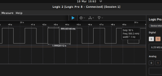
 The code turns the led on and off at 1 second intervals. You can see this in the software. This can be useful with a more complicated program to sink up events.
Data transfer
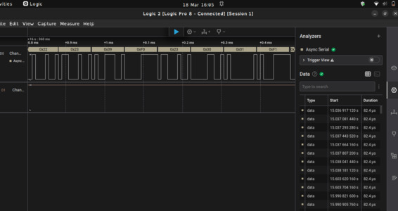
I recorded the signals when the arduino was getting flashed.
If you zoom in on the signals and use the analiser it can decode the serial signal.
Fade
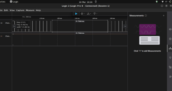
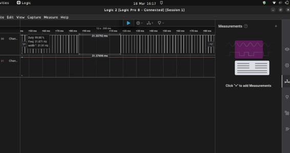
We then flashed the fade example code. YOu can see the lines getting closer together. It is important to realise the frequency stays at a constant 490, it is the signal gap that changes.
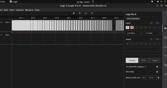
It is a bit deceptive. The area where it is dark is around 50% duty (equal amount of time on and off). This is because the gaps between the lines are greatest here.
The points where it apears most dense are 1% and 99% and it alternates.
Siganl is majority low.
Signal is majority high.
PWM
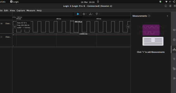
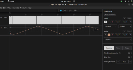
We also set up an example of filter that will covert PWM to a steady voltage.
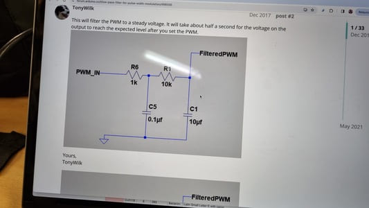
 We added a analogue channel to see the PWM signal.
I find this topic quite complicated. Here is a link to a chatgpt chat where it attempts to explain the topic.
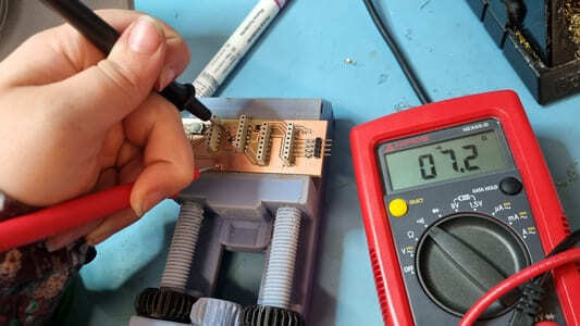
Multimeter
We used the multimeter to check for shorts on this weeks board. We had to use a 0 Ohm resistor to connect two ground areas so it was important to check this worked.