Sequence Storm Keyboard
As part of electronics design and electronics production weeks I set myself the task of creating a custom keyboard for the game sequence storm and then ordering them through a boardhouse to be produced.
Design requirements
I wanted the keybard to have these features:
Keyboard Layout
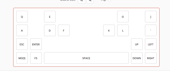
We start in Keyboard layout editor. This software helps visualise the board and the spacing of the keys.
This is the raw data of my board, this is useful for later as well.
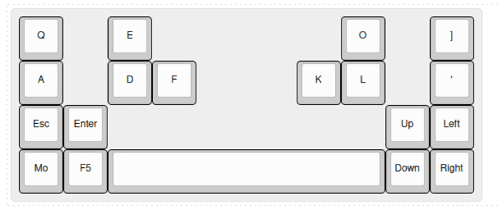
[{a:7},"Q",{x:1},"E",{x:4.25},"O",{x:1},"]"],
["A",{x:1},"D","F",{x:2.25},"K","L",{x:1},"'"],
["Esc","Enter",{x:6.25},"Up","Left"],
["Mo","F5",{w:6.25},"","Down","Right"]
KiCAD
I used a few useful guides to create the board. The instructional videos from Noah Kiser were a great help.
We also need to install the KiCAD libraries for useful key related footprints from marbastlib.
I want to use QMK for my board as it makes the process of coding the board easy as it is a standard which is well suported. Compatable microcontrollers. I decided to use a promicro clone, this is used quite a bit as they have lots of pins for the key matrix.
Schematic editor
I used 19 keys hotswap keys in my design and layed them out to match the designed board whilst also condensing some of the collums.
Each key has a diode to prevent ghosting when multiple keys are pressed. These are connected to the lower half of the key. I will use the SOD123 diode.
I also added components for the stabliser for my spacebar and the promicro.
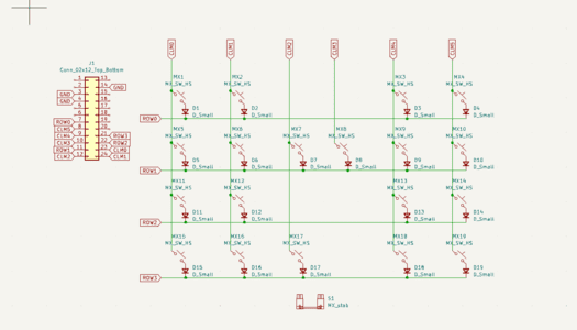
Run a wire to connect the keys into rows and collums.
Using global labels were very useful to connect the rows and collums easily and cleanly.
I used the 'Fill in schematic symbol reference designators' to make sure everything was labelled, important as there are 19 keys and 19 identical diodes and can be complicated when laying it out in th PCB editor.
Then we use the 'Run footprint assignment tool' to assign the right footprints. It isimportant here to choose the right size strablier for your board. The U size of the key can be found in the keyboard layout editor, the standard size for a spacebar is 6.25u.
We then can move into the PCB editor.
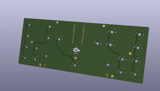
PCB editor
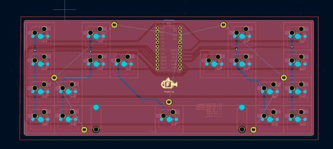
We update the PCB from the schematic which brings in a tangled mess of components which we then organise.
These components are actually going on the back of the PCB so we need to use F to flip them to the otherside.
We change the user grid to 0.79375mm(19.05/24) which allows you to line up the keys exactly.
The keys have a boundry box which makes it easy to line them up. Make sure you put the correct key in the right place to match the schematic. Then also match up the correct diode with the switch. Following the video I placed the diode bwteen the legs of the switch and it didn't cause any issues.
We now run tracks connecting the keys and diodes in their rows. The collums were easy, rows a bit more diffiuclt as I chose to place the promicro in the center of the board.
The tracks sometimes pass through the board using vias. In this case the collums all had to go through vias.
You can see the layers easily in the 3D viewer.
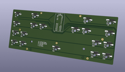
I added some silkscreen flair to the board. Created a simple logo in inkscape, added a parts list and a version number.
I also marked mounting areas using vias at the diameter of my screws.
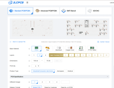
Ordering from a Board House
There are several available but I ended up going with JLC from a recomendation by one of our makers.
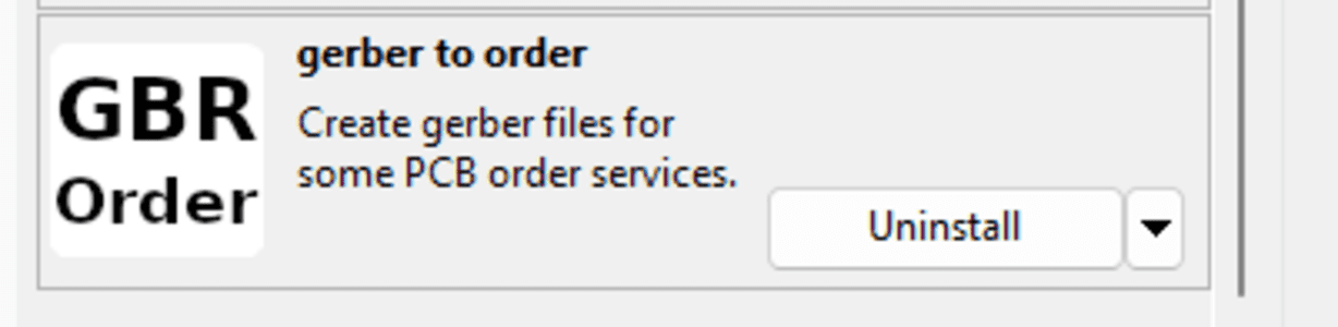
I used a plugin for kicad which exports the required files that need to be uploded to the website.
There are many options to customise the board and the website picks up the requirements from the design. My board is relativly simple and I am not using any assembly service it is quite simple. I did decide on a white silkscreen but very little needed to be changed.
There was some time where the design was checked. I am not sure what issues they will pick up as mine went through without issues.
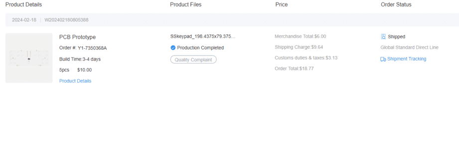
The process was painless and cheap considering what is made. I would be happy to use these services again.
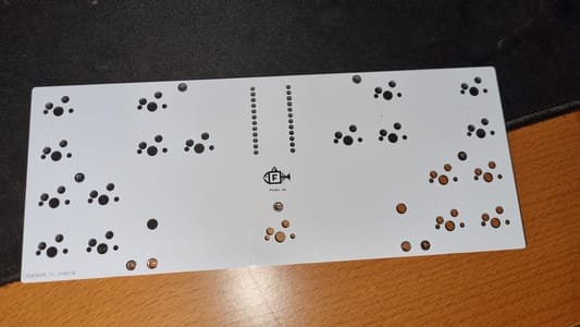
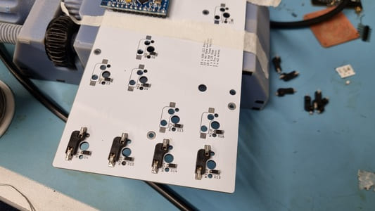
Soldering
The experience of soldering on these pretinned pads compared to the milled copper boards was surprising, it was a lot easier, however it did still take a lot of time even for my small board.
Programming
This video by Mad Mod Labs was very helpful in the next two steps of prgramming and making a case.
We use the website Keyboard Firmware Builder to build the QMK firmware specific to my board. You need to input the raw data frim the keyboard layout editor. This does some of the basics for you.
Wireing whould match your traces on the PCB
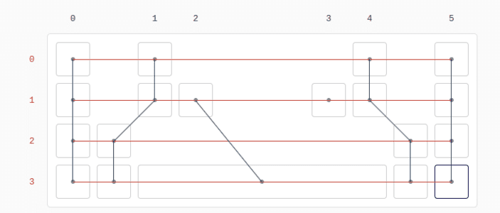
Pins is where you tell it which pin is resonsible for what row/collum.
Keymaps is where you tell it what each switch should output and you can set up multiple layers.
I skip macros and quantum tabs. Give it a name on the setting tab.
On the compile tab you can download the .hex file.
Flashing the board loads the microcontroller with the code. I use QMK Toolbox for this.
I had to place the pro micro into bootloader mode by bridging the reset pin with GND then flash the hex file.
The Keyboard tester website is useful to check if all the inputs are correct.
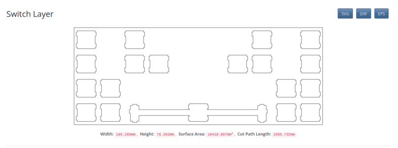
Modelling plate and case
The plate and case builder generates a SVG/DXF of the keyplate which can be imported into your 3D modeller of choice and be built upon and around.
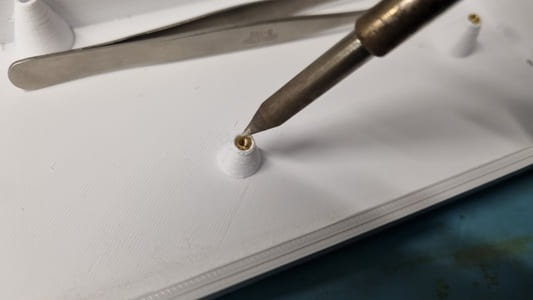
I designs standoffs to support the pcb and is how you mount it. I used heat set threads for the small screws to screw in to.
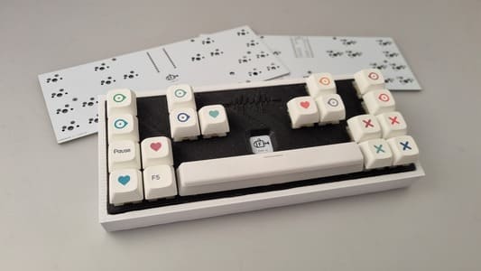
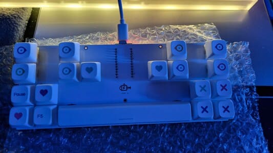
The finished board in its case. I had made the plate too close a fit to it required sanding to get it to fix in nicely. I also had to widen the usb hole slightly as the fillet i put on it was too large and got in the way of the board of the promicro.
I used Gateron milky yellow mechanical switches, Durgod v2 stabilisers and the keycaps are NP Crayons (unfortunatly no longer in production)